VA-700
I.R.
T.
Communications
Pty
L
t
d
|
www
.i
rtcommunications
.
c
o
m
Page 7 of 23
Revision 10
CONFIGURATION
The VA-700 may e configured for several modes of operation. This is achieved y various link settings as outlined
elow.
The VA-700 is normally delivered set for internal clamp operation and no su -modules fitted.
1. No su -module LK 2 - LK 3 soldered on oard.
LK 6 - LK 7 soldered on oard.
2. Su -module: See instructions for each module (O solete – no longer availa le. Reference for
previous modules sold already in existence).
Cable compensation:
Circuitry provides compensation for up to 300 metres of Beldin YR23769 ca le, links 8a and 8 are used to provide
ranging of the compensation.
A short on link 8a will allow for ca le lengths of 75 m - 300 m to e compensated.
Moving the link to position 8 will allow for ca le lengths of 0 - 75 m to e compensated.
Clamping option:
Decide if the clamp feature of the VA-700 is required. In general the clamp feature is useful if the video signal is
always composite.
If you are using the VA-700 to distri ute pulses or su -carrier the clamp feature should e disa led (LK 1 installed),
otherwise LK 1 should e removed.
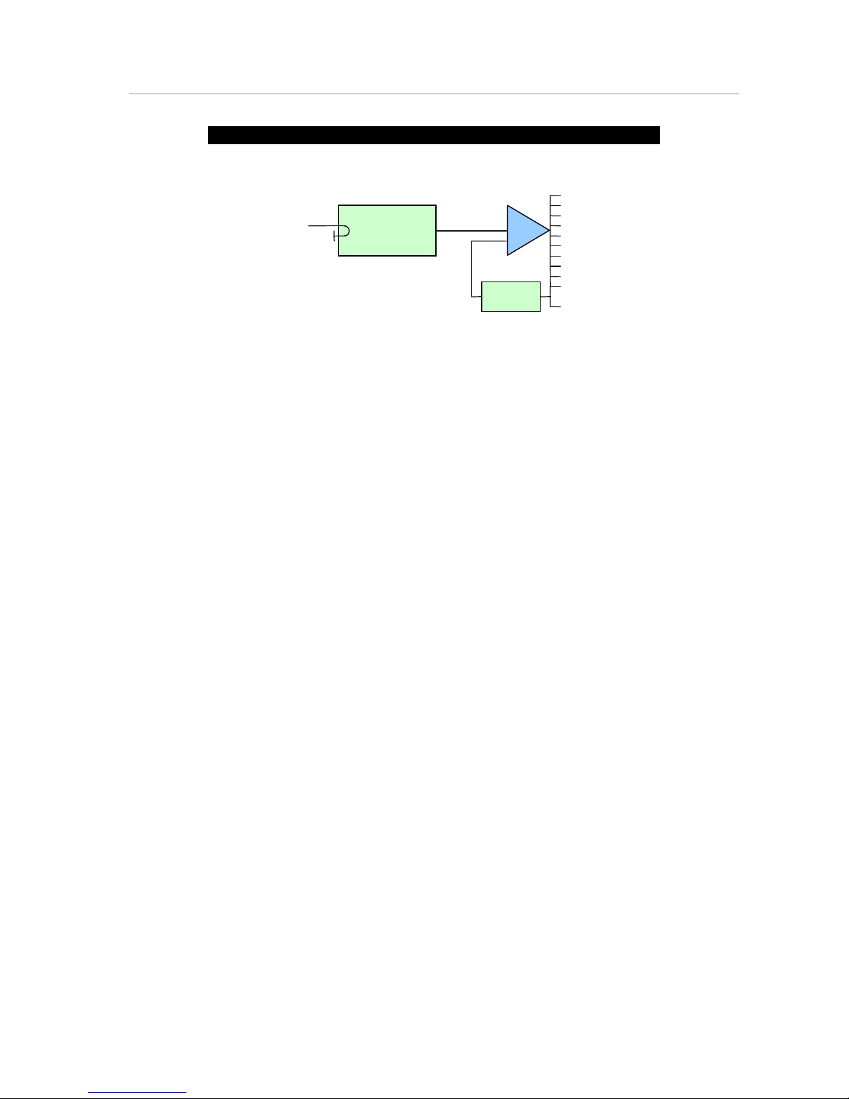
External clamp reference:
An external video signal can e used to provide the reference for the clamp pulse generator circuit in the VA-700.
The signal path from outputs 9 and/or 10 can e wired to the input of the clamp reference uffer amplifier.
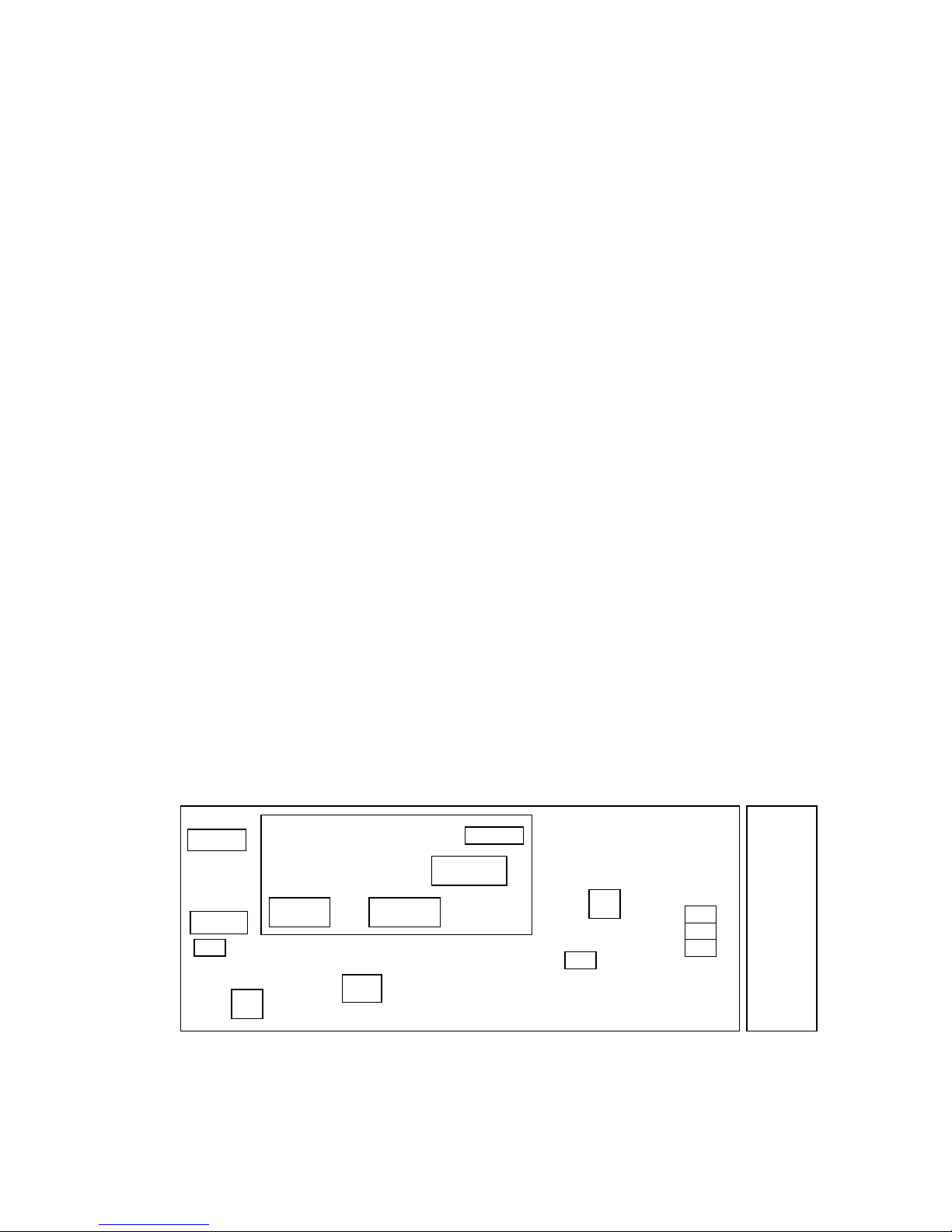
On the VDA remove the link etween LK 10 - LK 12,
and complete links LK 12 - LK 13, LK 14 - LK 15 and LK 16 - LK 17.
Remove R 70 and R 71 connect a wire link etween the rear pads of the R 70 position, the R 71 position and
the rear pad of the unused R 80 position.
The external clamp reference can now e looped through from the connector 9 and 10 positions on the rear
assem ly.
Alternately:
A terminated input for the external clamp reference can e provided y using only the output 10 connector
position.
On the VDA remove the link etween LK 10 - LK 12,
and complete links LK 12 - LK 13, LK 14 - LK 15 and LK 16 - LK 17.
Remove R 71 and insert in the R 80 position.
Now wire the end pads of R 80 and the R 71 position together.
This will give a terminated input for the external clamp reference from output connector 10 on the rear
assem ly.