3.
CIRCUIT DESCRIPTION
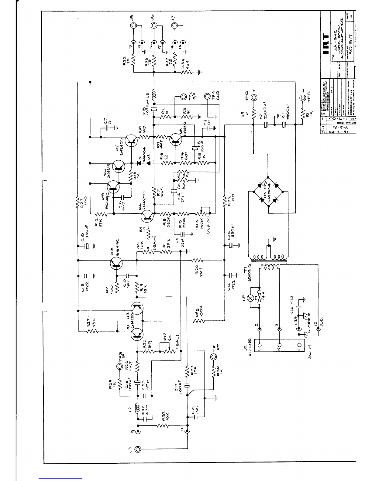
The AA-342 circuitry consists of two parts, an input amplifjer comprising
n'l fn o? :nd rn orrfnrrf emnlificr cnmnric'i nc C)4 tn OR The innrrt :mnlifipr
LU VJ vu Ll'u
is a djfferential input feed back amplifjer with unjty gain. Adjustment
of the comrnon-mode
hum rejection is rnade by VR2 the balance control.
Inductors LI,L2 and capacitors Cl9 to C22 comprise an RF fifter in the
input circujt. The output amplifjer is a complementary s1'mmetryemitler
follower feedback ampljfier with a gain of two. For correct operation
the DC voltage at the output as measured at the junction of Rl7, RIB
is set at +0.25 volts by adjustment of VR3 Lhe O/P DC control. Overall-
aain of fhc AA-?/1 :^ ^^! L" - cronf nancl nnttnted nntenfionefer VRl.
vuf,rr vr JaL !; >EL ty o J Lgu pvLsllLiulllsLs!
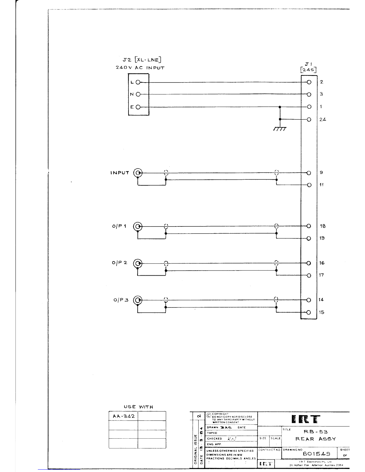
.Fn l.pon fhe o'rtn"+ :*^^,r--.^^ ^€ thc AA-342 arnnlifjer lOw 75 ohm fesjStors
are used t-o oistribute the output signal. This ensures that long cable
runs will not cause a ro11 off in the frequency response whilst still
rr-nvi6lir'6 c667t eirelit nrnter-tion for the amplifier,
OperaL:no voltaoes of 1t3 volts are supplied by the power supply comprjsjng
transiormer Tf and a half wave bridge rectifier D3 to D6 and C}, C2.