ISHIDA AC-4000B User manual


You can help improve this manual by calling attention to errors and by recommending improvements.
Please convey your comments to the nearest Ishida Company regional representative. Thank you!
Copyright 2002 by Ishida Co., Ltd. All Rights Reserved.
No part of this manual may be reproduced in any form, by mimeograph or any other means, without
written permission of the publisher.

Precautions
i AC-4000 Service Manual No.0181A
SAFETY CONSIDERATIONS
For safe operation, the following safety considerations must be observed.
Grounding
This machine requires protective grounding for safe operation. To avoid potential shock hazards, a
protective grounding conductor for the machine must be securely connected to the main grounding
provision by qualified service personnel.
Do not remove covers or enclosures
To avoid personal injury and shock, do not open or remove any covers or enclosures of the machine
unless specified in the manual.
Do not perform unspecified maintenance
For your personal safety, do not perform any maintenance procedures which are not specified in the
manual.
Disconnect power supply before servicing
To ensure your personal safety, disconnect the power supply before servicing.
SERVICE SAFETY
For correct maintenance, and to prevent accidents, please adhere to the following items dur-
ing service.
•Ensure that the power switch is OFF before any maintenance work and remove the power cable
from the main power outlet.
•Keep the machine surroundings clean and tidy. Take additional care, especially during disassembly,
not to leave screws etc. inside the machine as this may lead to serious injury.
•Do not pull internal wiring cables as cable breaks, poor contact, etc. may take place. Always hold
the connector end before removing. Take special care with thermal head cable, where poor contact
may lead to damage.
•Take care when cleaning thermal heads and print heads, as these are easily damaged.
•There are precautions relating to assembly and adjustment parts. Read and understand the manual
thoroughly before attempting maintenance.

Precautions
AC-4000 Service Manual No. 0181A ii
XWhen cleaning the machine, only use a
soft dry cloth or a cloth wetted with a
neutral cleanser.
Never use thinner or other volatile
liquids.
XDo not drop or apply a strong shock to the scale.
XDo not allow any liquids to come into con-
tact with the machine.
XDo not disassemble the machine.
Power Supply
•Use the appropirate voltage after referring to the specification
plate located on the machine.
•Use a dedicated power source.
(Voltage fluctuation may cause the machine to malfunction)

Precautions
iii AC-4000 Service Manual No.0181A
Avoid the following areas when installing the machine
Level adjustment
●Always ensure that the machine is level. If the machine is not level, weighing may not be accurate.
●Adjust the machine to a level position using the four level adjustment feet located on the buttom of
the machine, until the bubble is completely centered in the round level indicator.
●Areas subject to high temperatures or high
humidity
●Areas exposed to direct sunlight
●Areas where water or other liquids are
easily spilled on the machine
●Areas subject to a lot of dust or dirt
●Areas with large voltage fluctuations
●Areas subject to excissive vibration or
unstable surfaces
●Areas exposed to direct cold air
●Areas subject to low temperatures
●Areas where the scale is not level

Contents
AC-4000 Service Manual No. 0181A iv
Contents
CHAPTER 1 OVERVIEW .............................................................................................. 1-1
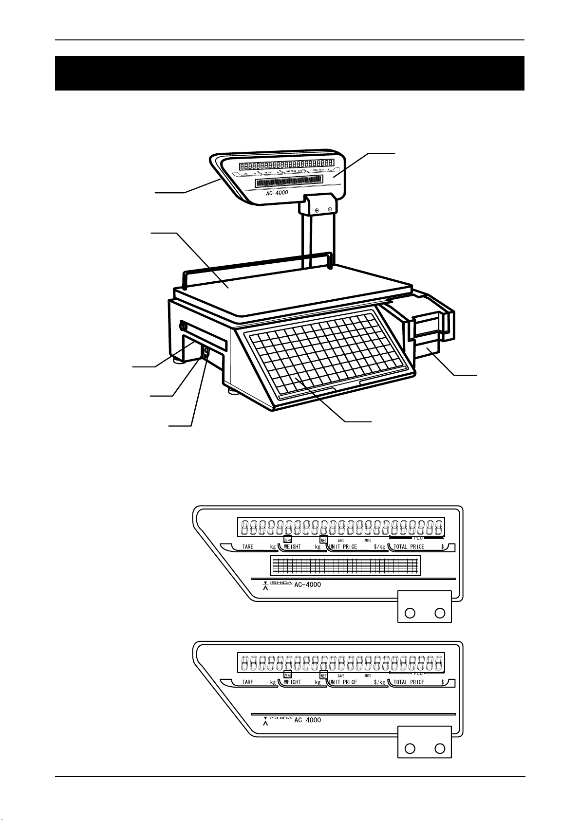
1.1 Appearance and Name of Each Part.................................................................................. 1-1
1.2 Display ................................................................................................................................ 1-1
1.3 Key Sheet ........................................................................................................................... 1-2
1.4 Printer ................................................................................................................................. 1-2
1.5 Main Specifications ............................................................................................................ 1-3
1.6 Exploded Drawing .............................................................................................................. 1-4
CHAPTER 2 INSTALLATION ........................................................................................ 2-1
2.1 Packed Goods .................................................................................................................... 2-1
2.2 Installation Environment ..................................................................................................... 2-2
2.3 Assembly ............................................................................................................................ 2-2
2.4 Weigh Platter Installation.................................................................................................... 2-3
2.5 Label Loading ..................................................................................................................... 2-3
2.6 Power Cable Connection.................................................................................................... 2-4
2.7 Turning Power Switch “ON” ............................................................................................... 2-4
2.8 Customer’s Specification Setup ......................................................................................... 2-5
(Initialization, Setup, and Registration) .............................................................................. 2-5
2.9 Normal Mode Display ......................................................................................................... 2-6
2.10 Label Batch Print Mode ...................................................................................................... 2-7
2.10.1 Basic operation ...................................................................................................... 2-7
2.10.2 Additional functions ................................................................................................ 2-7
2.10.3 Label batch printing on continuous paper ............................................................. 2-8
2.11 Scroll Message Display ...................................................................................................... 2-9
2.12 Campaign Function ............................................................................................................ 2-9
CHAPTER 3 TEST MODE............................................................................................. 3-1
3.1 Test Mode Menu List .......................................................................................................... 3-1
3.2 Test Mode Start .................................................................................................................. 3-2
3.3 Hardware Test .................................................................................................................... 3-2
3.4 RAM Clear .......................................................................................................................... 3-7
3.5 Printer Head ..................................................................................................................... 3-11
3.6 Label Sensor Check ......................................................................................................... 3-13
3.7 Total Memory .................................................................................................................... 3-14
3.8 ROM Switch ..................................................................................................................... 3-15
3.9 Peel Sensor Check ........................................................................................................... 3-17
CHAPTER 4 SETUP MODE .......................................................................................... 4-1
4.1 Setup Mode Menu .............................................................................................................. 4-1
4.2 Starting Procedure for Each Mode ..................................................................................... 4-2
4.3 Starting Procedure for Setup Mode .................................................................................... 4-2
4.4 Label Format [Print conditions] .......................................................................................... 4-3
4.5 POS Code .......................................................................................................................... 4-8
4.6 Barcode [Item code] ......................................................................................................... 4-11

Contents
v AC-4000 Service Manual No. 0181A
4.7 Default Data ..................................................................................................................... 4-12
4.8 Total Mode Select ............................................................................................................. 4-13
4.9 Forced Tare [USA specification only] ............................................................................... 4-13
4.10 Open Price [Prohibition of Unit Price Change] ................................................................. 4-14
4.11 PLU Select [Editing PLU File] ........................................................................................... 4-15
4.12 System [Availabilty of Registration Mode Menu] .............................................................. 4-22
4.13 Ethernet Setup [Ethernet Data Setting] ............................................................................ 4-26
4.14 System Timer ................................................................................................................... 4-32
4.15 Password Setup ............................................................................................................... 4-33
CHAPTER 5 ELECTRICITY COMPOSITION ................................................................ 5-1
CHAPTER 6 TROUBLESHOOTING ............................................................................. 6-1
6.1 Error List ............................................................................................................................. 6-1
CHAPTER 7 PARTS REPLACEMENT ......................................................................... 7-1
7.1 Detaching Each Part (Unit)................................................................................................. 7-1
7.2 Detaching Internal Parts ..................................................................................................... 7-4
7.3 Periodical Replacement Parts .......................................................................................... 7-14
7.4 How to Pass Labels.......................................................................................................... 7-14

Chapter 1 Overview
1-1 AC-4000 Service Manual No. 0181A
CHAPTER 1OVERVIEW
1.1 Appearance and Name of Each Part
1.2 Display
AC-4000B
AC-4000E
Customerdisplay
Operatordisplay
Weigh platter
Power switch
Power supply
receptacle
Fuse Printer
Key sheet
Upper surface: Operation key sheet
Lower surface: Program key sheet

Chapter 1 Overview
AC-4000 Service Manual No. 0181A 1-2
1.3 Key Sheet
1.4 Printer
Windingbobbin
Shafttension
Aligningcollar
Base label
Peel shaft
Set lever
Label pressure plate
Thermal head
Peelsensor
Labelsensor

Chapter 1 Overview
1-3 AC-4000 Service Manual No. 0181A
1.5 Main Specifications
Item
Weighing capacity
Minimum graduation
Weighing accuracy
Load cell
Size of main body
Weigh platter material and size
Printer
Label roll size
Label length
Sensor
Key
Display
Operating temperature
Operating humidity
Power supply
Power consumption
Weight
Memory capacity
Interface
Cash drawer
TCP/IP
LAN cable
SRAM
Content
15kg or 30lb
2g/5g or 0.005 lb/0.01 lb
1/3000 (Dual-range)
HBM made
450(W) x 420(D) x 440(H) mm
SUS430...400(W) x 250(D) mm
Backing paper width...Max. 67mm, Label width...38 to 64mm,
Effective print width...Max. 60mm, Print speed...80mm/second
Inner diameter: 40mm, Outer diameter: 100mm
30 to 175mm
Label sensor, Peel sensor
Membrane switch (120 keys)
Fluorescent display tube: 23 digits
(Both for customer and operator displays)
Character height: 10.1mm, 256 x 16 dots
-5 to 40°C
Main body: Max. 95% (40°C), No condensation
Printer: Max. 80% (40°C), No condensation
Varies depending on where the machine is used.
(Specified on the rating plate)
Stand-by: Approx. 40W
Operating: Approx. 100W
11kg
Standard: 1MB
Factory option: 2MB
RS232C (D-sub 9 pin)
Output: DC24V/500mA
10 baseT
Direct connection: Crossing cable
When using Hub: Straight cable
1M bytes (1,024k bytes)
SRAM mapping
1. Fixed data: Approx. 19k bytes
Approx. 1k bytes for fixed data year, print speed, and print density,
etc., and the remainder is the reserves.
2. Logo data: Approx. 56k bytes
3. SRAM file: Approx. 949k bytes
949k bytes for registration
9k bytes for file creation (940k bytes available after RAM is
cleared)
PLU, Store name/address, Extra message 1/2/3, Coupon,
Preset, Label format, Field title, and Operator

Chapter 1 Overview
AC-4000 Service Manual No. 0181A 1-4
1.6 Exploded Drawing
AC-4000
TAREkg
WEIGHTkg
UNITPRICE$/kgTOTALPRICE$
++
Weigh platter
Platter holder
Display
Load cell
Power supply
Fuse
Power switch
Module RS232C
Power cable
PK-229
(A/D board)
P-950A
(Main board)
Operationpanel
(Key sheet)
Top case

Chapter 2 Installation
2-1 AC-4000 Service Manual No. 0181A
CHAPTER 2INSTALLATION
2.1 Packed Goods
Open the packing case and check whether there are all the packed goods (machine and accessories) and
if there are any damaged parts.
Note: AC-4000 “B type” or “E type” can be identified by a description of the sticker on the case.
[Packed goods]
1. Stand
2. Power cable
3. Thermal head cleaner
4. Main body
5. Display
6. Weigh platter
7. Operation manual

Chapter 2 Installation
AC-4000 Service Manual No. 0181A 2-2
2.2 Installation Environment
•Install the machine on the stable and horizontal place.
•Install the machine in the place where the liquid such as
water does not splash.
•Avoid the place where direct sunshine strikes for a long
time.
•Install the machine in the place where the influence such
as the winds is not received.
•Secure the installation space enough.
2.3 Assembly
1. Run the display connector (harness) through the stand,
and fix the display and the stand with the 4 screws
(A).
2. Engage the connector with the connector on the main
body.
3. Insert the two bosses of the stand into the main body.
4. Tighten the stand and the main body with the 2 screw
(B). Screw (A)
(M4 x 8)
Screw (A)
Screw (B) (M4 x 8)
Stand
Harness
Connector
Boss Main body
Display

Chapter 2 Installation
2-3 AC-4000 Service Manual No. 0181A
2.4 Weigh Platter Installation
Insert the 4 pins of the weigh platter into the rubber feet on the platter holder.
2.5 Label Loading
•Open the side cover of the main body.
•Load the label roll as shown in “How to pass labels”.
Label roll
How to pass labels
Side cover
Weigh platter

Chapter 2 Installation
AC-4000 Service Manual No. 0181A 2-4
2.6 Power Cable Connection
•Insert the power cable into the receptacle at the left of the main body.
•Insert the power cable plug into the power outlet.
Ensure to establish a ground at the customer side.
110 V /220 V input power supply can be used. However, set the jumper lead to the required
voltage display side before the power is turned ON.
Power outlet
power cable
Power receptacle
The power outlet shape varies according to customers.
2.7 Power Switch “ON”
•Turn on the power switch located at the left side of
main body.
Note: Push the “O” side of the switch to urn off the power.

Chapter 2 Installation
2-5 AC-4000 Service Manual No. 0181A
2.8 Customer’s Specification Setup
(Initialization, Setup, and Registration)
Set up required specifications according to the following sequence.
Test mode (Refer to Chapter 3 “Test Mode”)
1. Hardware test................................................................ P.3-2
2. RAM clear ..................................................................... P.3-7
3. Printer head................................................................... P.3-11
4. Label sensor check ....................................................... P.3-13
5. Total memory ................................................................ P.3-14
6. ROM switch .................................................................. P.3-15
7. Peel sensor check ......................................................... P.3-17
Setup mode (Refer to Chapter 4 “Setup Mode”)
1. Label format ................................................................ P.4-3
2. POS code .................................................................... P.4-8
3. Barcode ....................................................................... P.4-11
4. Default data ................................................................. P.4-12
5. Total mode select ........................................................ P.4-13
6. Forced tare .................................................................. P.4-13
7. Open price .................................................................. P.4-14
8. PLU selection .............................................................. P.4-15
9. System ........................................................................ P.4-22
10. Ethernet setup ............................................................. P.4-26
11. System timer ............................................................... P.4-32
12. Password setup .......................................................... P.4-33

Chapter 2 Installation
AC-4000 Service Manual No. 0181A 2-6
2.9 Normal Mode Display
1. All segments blink three times when the power is turned on.
2. Then, the initial display appears.
■■
■■
■Operator display
■■
■■
■Customer display
3. When calling up “Fixed price item” or “Weighing item”.
■■
■■
■Weighing item
■■
■■
■Fixed price item

Chapter 2 Installation
2-7 AC-4000 Service Manual No. 0181A
2.10 Label Batch Print Mode
•The following display appears when printing batches of labels.
•The label batch printing is a function which prints the item data and the number of labels registered in
advance a for fixed price items.
•Maximum number of specified items: 99 commodities
•Maximum number of specified labels: 9,999 labels
•Preset key number: 19 presets
Note: Registered data is cleared when the power is turned OFF.
2.10.1 Basic operation
•Assign the BATCH PRINT key (Preset key number: 19) to any one of preset keys.
P04-01-01 screen menu ..... 19 + FEED + 0 + Preset key
•Press the LABEL BATCH key to enter the label batch print mode.
This function is available before an item is called up.
1. Call up a fixed price item.
Key in an item number, then press the PLU key.
Note: An error buzzer sounds when other item is called than fixed price item.
2. Specify the number of labels to be printed.
Key in the number of labels, then press the ENTER key.
Note: An error buzzer sounds when the limited number of labels (9,999 labels) exceeds.
3. Repeat above steps 1. and 2. to specify the number of labels for other items.
Note: An error buzzer sounds when exceeding the maximum number of specified items (99 items).
4. Press the PRINT key to start printing. Then, printing starts in the sequence from the most recently
registered item.
Note: An error buzzer sounds when there is no item registered for label batch printing.
5. The machine returns to the normal mode after all registered items are printed.
2.10.2 Additional functions
1. End of the label batch print mode
The machine returns to the normal mode when the MODE key is pressed.
The registered data is preserved as it is if there are any registered items.
2. Printing preserved data
If there is any preserved print data, printing starts by pressing the PRINT key.
Note: An error buzzer sounds if there is no registered data.

Chapter 2 Installation
AC-4000 Service Manual No. 0181A 2-8
3. Deleting label batch print data
The label batch print data is deleted while sounding an OK buzzer by pressing the ZERO key twice.
4. Stop of label batch print operation
Label batch print stops by pressing the PRINT key while printing a print reservation data.
However, the remaining label batch print items are not deleted.
(If printing stops when five labels have been issued for an item specified to issue 10 labels, the
remaining 5 labels are preserved.)
5. Addition of label batch print data to the preserved data
The label batch print data is added to the preserved data.
(When there are “40 preserved items”, “59 items” can be added.)
2.10.3 Label batch printing on continuous paper
The same operation is applied for continuous paper which is set in the B01-01-05 menu.
Refer to 4-4 in Chapter 4.

Chapter 2 Installation
2-9 AC-4000 Service Manual No. 0181A
2.11 Scroll Message Display
•A function to display the registered scroll message. When an item has not been called up, it starts after
five seconds have passed.
•Display method registration function
(0: No display 1: High-speed scroll 2: Normal scroll 3: Low-speed scroll 4: High-speed blinking
5: Normal blinking 6: Low-speed blinking)
•Day of the week registration function
(0: Every day 1: Sunday 2: Monday 3: Tuesday 4: Wednesday 5: Thursday 6: Friday 7: Saturday)
•Display time registration function (Start/stop)
[Example] 09:00 to 13:00
Enter “0913” and press the ENTER key.
•Maximum number of scroll messages: 9 messages (1 to 9)
•Maximum number of characters: 96 characters (one byte English code)
2.12 Campaign Function
•Registered campaign items start to be sold at the registered campaign price when the time reaches
registered campaign time.
•Maximum number of campaign: 20
•Maximum number of items for each campaign: 100
•Discount method
(0: Unit price 1: Special price 2: Amount discount 3: Percent discount 4: Special unit price)
•Campaign 1 becomes top priority for items registered during the overlapping time.
•Priority is given from Campaign 1, 2, and 3 to the last 20 if the same item is registered.
That is, priority is given to the campaign 1 even if the same item is registered in campaign 1 and 2
during the overlapping time.
•Registration of the same item is not supported in one campaign.
•An error message appears when a label is issued with a registered price in the campaign greater than
the weighing price.
Other manuals for AC-4000B
1
This manual suits for next models
1
Table of contents
Other ISHIDA Printer manuals

ISHIDA
ISHIDA AC-4000 Series User manual

ISHIDA
ISHIDA 100-040-3749-00 Owner's manual

ISHIDA
ISHIDA BC-4000TEC User manual

ISHIDA
ISHIDA Astra User manual

ISHIDA
ISHIDA AC-4000H User manual

ISHIDA
ISHIDA AC-3OOO User manual

ISHIDA
ISHIDA Astra User manual

ISHIDA
ISHIDA AC-4000 Series User manual

ISHIDA
ISHIDA AC-4000 Series User manual

ISHIDA
ISHIDA AC-4000H User manual