ITALCOPPIE SENSORI EvominiSER User manual

IMB222 Rev.4.05 May 2022
1
EvominiSER
Transmitter with Modbus RTU
output signal and I2C digital
sensors or RTD input
USER’s MANUAL

IMB222 Rev.4.05 May 2022
2
Summary
1 General safety rules .................................................................................................... 4
1.1 Recommendations for workers ............................................................................ 4
1.2 Typical applications ........................................................................................... 4
1.3 Safety rules ...................................................................................................... 4
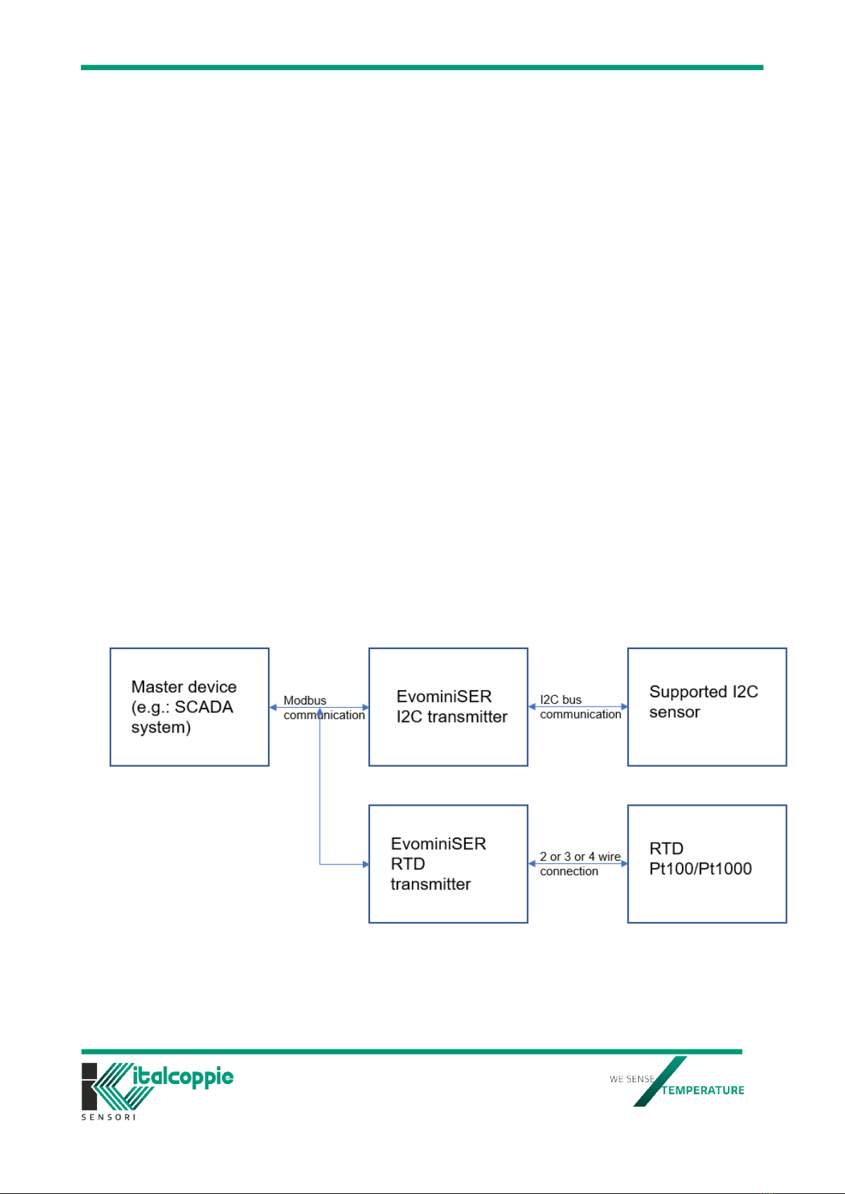
2Introduction ........................................................................................................... 5
2.1 Working principle .............................................................................................. 5
3Installation ............................................................................................................ 6
3.1 Mounting instructions ........................................................................................ 6
3.2 Operating conditions.......................................................................................... 6
3.3 Electric connections ........................................................................................... 6
3.3.1 Power supply requirements.............................................................................. 7
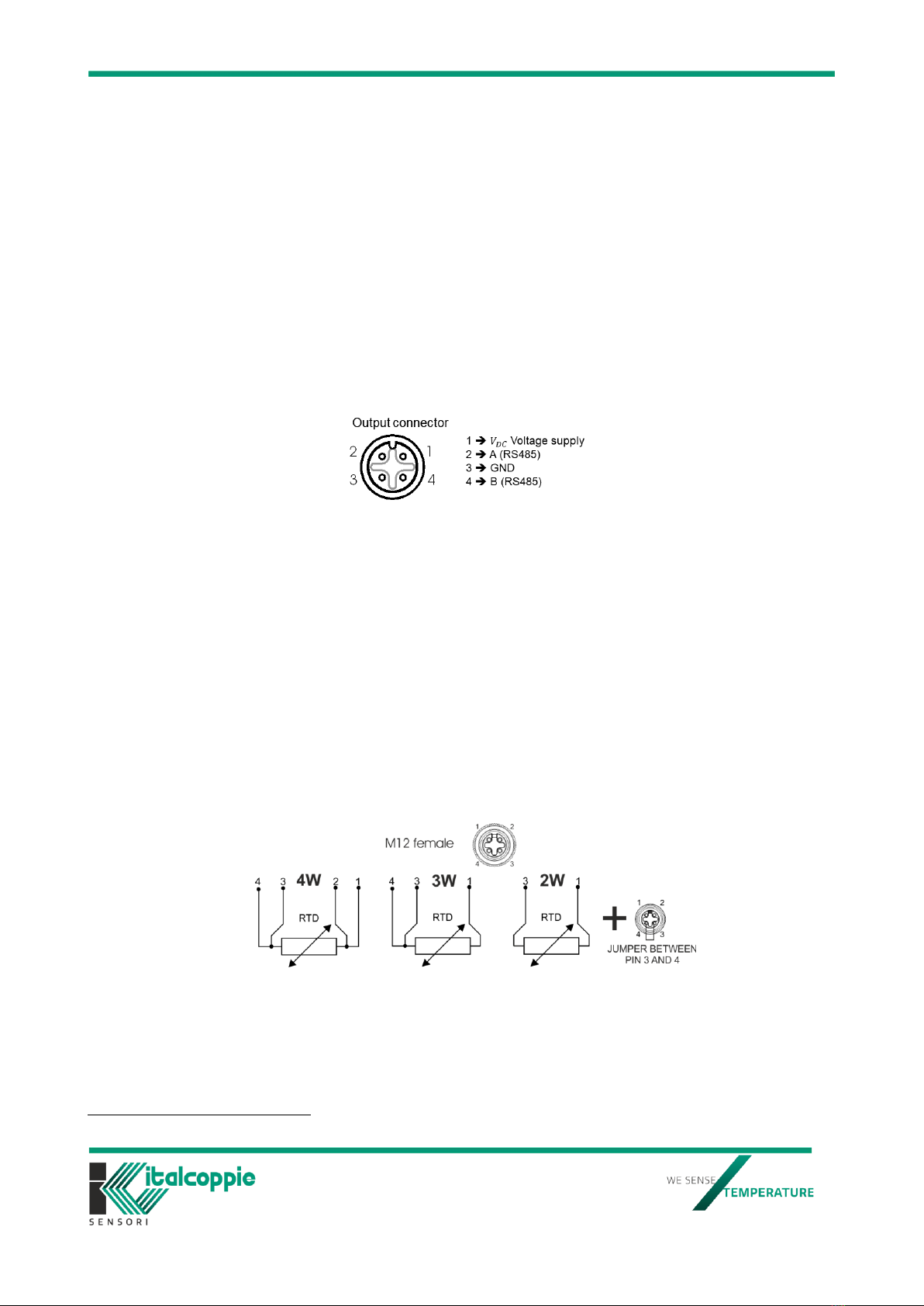
3.3.2 Pinout and connections ................................................................................... 7
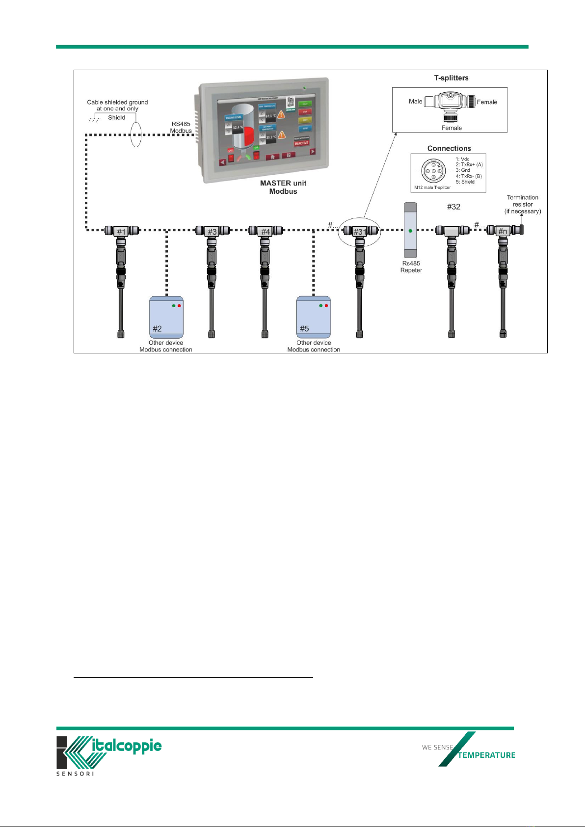
3.3.3 Cabling good practices .................................................................................... 8
3.3.4 Polarity ......................................................................................................... 9
3.3.5 Terminating impedance ................................................................................... 9
3.3.6 Allowed maximum number for series connected transmitters ............................... 9
4 Mechanical dimensions .......................................................................................... 10
5 Technical data ...................................................................................................... 11
5.1 LED indicators .................................................................................................... 12
6 Certifications ........................................................................................................ 12
7 Options ............................................................................................................... 13
7.1 Isolator / Serial repeater .................................................................................. 13
7.2 Connection cables ........................................................................................... 14
7.3 Extension cables with M12 connectors ............................................................... 15
7.4 T distributor for digital transmission .................................................................. 15
7.4.1 T distributor for digital transmission with integrated extension cable ................... 16
7.5 Wall fixing bracket........................................................................................... 17
7.6 Configuration kit ............................................................................................. 17
8 Order code........................................................................................................... 18
9. Compatible sensors.................................................................................................. 19
9.1 Temperature and relative humidity sensor.......................................................... 19
9.2 Temperature sensor with magnetic connector ..................................................... 20
9.3 Sensor for ambient ligh.................................................................................... 21
9.4 RTD temperature sensor .................................................................................. 23
10. Modbus registers table............................................................................................ 23
10.1 Modbus communication parameters................................................................ 23
10.1.1 Modbus communication parameters description .............................................. 24
10.2 Device parameters ....................................................................................... 25
10.2.1 Device parameters description...................................................................... 25
10.3 System parameters ...................................................................................... 27
10.3.1 System parameters description .................................................................... 27
10.4 Set sensor type............................................................................................ 29
10.4.1 Set sensor type description .......................................................................... 29
10.5 User data (available only on EvominiSER-RTD item) ......................................... 29
10.5.1 User data description .................................................................................. 30
10.6 Process data ................................................................................................ 32
10.6.1 Process data for temperature and relative humidity sensor .............................. 32
10.6.2 Process data for temperature and relative humidity sensor description .............. 32
10.6.3 Process data for surface temperature sensor .................................................. 33
10.6.4 Process data for surface temperature sensor description.................................. 33
10.6.5 Process data for Lux sensor ......................................................................... 34
10.6.6 Process data for Lux sensor description ......................................................... 34

IMB222 Rev.4.05 May 2022
3
10.6.7 RTD temperature sensor process data ........................................................... 35
10.6.8 RTD temperature sensor process data description ........................................... 35
10.6.9 Fast start of device at power-on ................................................................... 36
11. Modbus coils table.................................................................................................. 36
11.1 Coil description ............................................................................................ 37
12 Modbus RTU......................................................................................................... 38
12.1 Introduction to Modbus protocol..................................................................... 38
12.2 Master-slave protocol model .......................................................................... 38
12.3.1 CRC-16 ..................................................................................................... 39
12.3.2 CRC16 flow chart ........................................................................................ 40
12.3.3 Message synchronization ............................................................................. 40
12.4 Modbus function codes.................................................................................. 41
12.4.1 Read coil/input status (01 or 02) .................................................................. 41
12.4.2 Read holding/input registers (03 or 04) ......................................................... 42
12.4.3 Force single coil (05)................................................................................... 42
12.4.4 Preset single register (06)............................................................................ 43
12.4.5 Preset multiple registers (16) ....................................................................... 44
12.4.6 Modbus exception responses ........................................................................ 45
13 EVOSER compatibility ............................................................................................ 46
13.1 How to set the EVOSER compatibility ............................................................... 46
14 Device setup with EvoPlatform ............................................................................... 47
14.1 Configure EvominiSER .................................................................................. 49
14.1.1 Set desired COM parameters and Modbus address .......................................... 49
14.1.2 EvominiSER information and setup................................................................ 50
14.1.3 Online features........................................................................................... 50
14.1.4 Data monitoring ......................................................................................... 51
14.1.5 Factory settings.......................................................................................... 51
14.1.6 Configuration file ........................................................................................ 54
15 Firmware update .................................................................................................. 55
15.1 Firmware update at the power-on device ............................................................. 57
15.2 Update Firmware from BOOT(red LED on after power-on device) ............................ 59
16 Troubleshooting.................................................................................................... 61
16.1 Communication errors .................................................................................. 61
16.2 LEDs are off after device power up ................................................................. 61
16.3 ERR LED ..................................................................................................... 61
16.4 PWR LED..................................................................................................... 61

IMB222 Rev.4.05 May 2022
4
1 General safety rules
Before performing any operations on the device, read carefully the following
recommendations:
¤ Before hooking up the device, read the installation instructions given in this manual.
¤ To wire up the device, a proper wiring size must be chosen according to voltage and
current specifications found in technical data.
¤ The device is not equipped with an ON/OFF switch. Therefore, it powers up immediately
as soon as power is supplied to it.
¤ The device must be powered with DC voltage greater than 9V and lower than 32V. Higher
voltages will cause device failure while lower voltages will not allow the device to work
properly.
¤ Make sure that the working environment conditions falls within the range specified in
chapter 6 ‘Technical data’
¤ The device is not designed for operation in hazardous atmospheres (i.e., flammable or
explosive): its use in such conditions is therefore prohibited.
¤ The device is intended for industrial use only. Do not use the device in situations where
compliance with strict safety precautions is required, such as applications directly or
indirectly correlated with medical equipment.
¤ The device must not be disassembled or repaired by unauthorised people. Contact your
local dealer for any repairs.
1.1 Recommendations for workers
When performing their tasks, workers should observe the following recommendations:
¤ Workers with specific qualifications for assigned tasks are required
¤ Workers must be authorised by the plant's owner/operator
¤ Workers must be familiar with federal/national regulations
¤ Before doing any action, workers must read and understand the instructions given in the
manual and the supplementary documentation (if available and depending on the
application)
¤ Workers must comply with the instructions and basic conditions
1.2 Typical applications
Typical applications include HVAC systems (heating, ventilation, and air conditioning),
agriculture, incubators, cold rooms, standard measurements, seasoning rooms etc.
¤ Only use this device in full compliance with the general conditions listed in this manual
and, if applicable, in the additional documentation.
Improper use:
Italcoppie Sensori s.r.l. is not liable in any way for damage or injury caused by
tampering, incorrect or improper use of the device.
1.3 Safety rules
Refer to the relevant regulations.
Read and carefully follow the instructions given in this manual

IMB222 Rev.4.05 May 2022
5
2Introduction
The EvominiSER is a programmable digital transmitter with Modbus RTU output. It can be
connected to different sensors in order to detect different data, such as temperature,
humidity, light etc. Two different versions can be ordered: the EvominiSER I2C, that can be
connected with various supported I2C digital sensors and the EvominiSER RTD, that can be
connected with RTD Pt100/Pt1000 2 or 3 or 4 wire connection.
In this manual the model with I2Cbus input will be mentioned as EvominiSER-I2C (item code
EVO032) while the model with RTD input will be mentioned as EvominiSER-RTD (item code
EVO040 for the model without sensor, EOSI # and ESTP # for models with integrated
sensor).
By using a specific cable, several EvominiSER can be connected in series. One device only
can be a master.
With its small size, low-cost, IP67 degree of protection, easy-cabling and use quality, it is an
extremely interesting equipment for several applications in industrial environment (e.g.,
HVAC systems). Its M12 connectors allow for a fast and easy cabling feature.
Furthermore, by using this transmitter it is possible to implement modular systems. If one
or more devices are to be added to the network, it will not be necessary to design again the
measurement system. Thus, no added design costs are to be sustained.
The Modbus protocol is a very popular standard for field bus applications due to its reliably
and capability of efficiently handling large data flows. With the Modbus implementation, the
Evo series can be hooked up directly to the majority of commercially available PLC’s and
SCADA packages, with the option to connect these modules together with other devices
(PLC’s, operator panels, CNC equipment, etc...) over a single network.
2.1 Working principle
The EvominiSER block diagram is shown in Figure 1.
Figure 1: EvominiSER block diagram
A master unit, e.g., a PLC unit or a PC with SCADA (Supervisory Control And Data Acquisition)
has to be connected to the network for data monitoring.

IMB222 Rev.4.05 May 2022
6
3Installation
WARNING!
This device must be installed by qualified and authorized people.
3.1 Mounting instructions
A picture of the EvominiSER is shown in Figure 2.
Figure 2: EvominiSER
In order to serially connect several transmitters, a specific M12 tee connector can be ordered
together with its extension cables (for details refer to chapter 7).
A specific sensor can be connected using an M12 connector by screwing it to the metallic
threaded ring. The connection is IP67.
“I2C” is marked on the body of the device to identify the EvominiSER model with input for
digital sensors, “RTD” for the model with Pt100 or Pt1000 RTD input.
3.2 Operating conditions
Installing ambient temperature: (-40÷ +80) °C
Installing ambient relative humidity: (0 ÷ 100) %
Protection degree: IP67 according to IEC 60529
3.3 Electric connections
The EvominiSER comes with two 4-pole M12 connectors. A series connection of transmitters
can be arranged by using an overmolded extension cable with a 4-pole M12 female
connector. Tee connectors are available to extend the network. This solution allows for an
IP65/IP67 connection. It is possible to use other commercially available female M12
connectors. In such a case, the degree of protection depends upon the cabling system.
WARNING!
The electric connections shall be executed as described in the following chapters.
Cabling errors might break either the device or the entire devices’ network.

IMB222 Rev.4.05 May 2022
7
3.3.1 Power supply requirements
¤ Device power supply: typical 24, or within (9 ÷ 32) range.
¤ Use a power supply with a 24 output, according to ELV regulations.
¤ Maximum current consumption: 10mA (at power-on for about 8 ms).
¤ Average current consumption: about 4mA.
On the power line, insert an insulation switch together with an appropriate fuse. The voltage
supply must be continuous, isolated and with low ripple.
3.3.2 Pinout and connections
The pinout of the output connector is shown in Figure 3.
Figure 3: M12 male output connector pinout
WARNING!
•The device is protected against polarity inversion.
•In case of incorrect electrical wiring, the device is protected only for voltages less than
25. A misconnection with higher voltages will cause a device failure.
The EvominiSER comes with half-duplex EIA RS-485 serial interface. The cabling is simplified
by the M12 connectors
1
.
WARNING!
The device serial interface is not Galvanically isolated. If the master unit is equipped with
RS232 serial interface, an isolated transceiver should be used. If the master unit is equipped
with RS485 serial interface, a converter with Galvanic isolator should be used. As an option,
a RS485 repeater/isolator can be ordered (cod. EVO005).
Figure 4a: RTD sensor connection, M12 female (for item EVO040 only)
Note: for 2W connection a jumper between pin 3 and 4 must be made (as close as possible
to M12 female connector)
1
4-pin M12x1 male connector (according to IEC 61076-2-101)

IMB222 Rev.4.05 May 2022
8
Figure 5: application example
3.3.3 Cabling good practices
The RS485 (EIA-485) is a standard defining the electrical characteristics of drivers and
receivers for use in serial communications systems. Electrical signal is balanced, and
multipoint systems are supported. Ideally, the two ends of the cable will have a termination
resistor connected across the two wires. Without termination resistors, signal reflections off
the unterminated end of the cable can cause data corruption. Termination resistor also
reduce electrical noise sensitivity due to the lower impedance. The value of each termination
resistor should be equal to the cable characteristic impedance (typically, 120Ω for twisted
pairs). The master is usually already equipped with the termination resistance. The maximum
length is not defined as depends upon the data rate, the signal-to-noise ratio and the cable
quality.
There are some good practices that allows for external interference reduction. Cables that
carry higher currents to power devices should be kept as far as possible from cables that
carry communication signals. Cables reserved for communication signals must be kept as far
as possible from power switching devices, such as contactors and relays, as well as from
electric motors and generators. Choosing a cable suited for the particular application is also
considered a good practice. In particular, the lower its capacitance per meter the longer the
network can be. Typically, the cable should have a value within the range (50 ÷ 100)pF/m.
The RS485 consists of two conductor cables and twisted pair cabling is suggested to ensure
that each conductor is equally exposed to any external magnetic fields that could induce
unwanted noise. A metallic electrostatic shielding is also suggested to provide immunity to
RF interference.
A star topology network is not recommended. As explained above, a 120Ω termination
impedance is required for the two end line termination devices to avoid reflections. Therefore,
a very low impedance will result from a star topology network. Thus, no communication can
result at a certain point.

IMB222 Rev.4.05 May 2022
9
3.3.4 Polarity
According to RS485/422 standard, the signal connections are indicated with A and B.
However, it might be possible to find different indications on some products, such as HI/LO
or +/-. If a device is unable to connect to the network, try inverting A and B and to connect
the device again.
3.3.5 Terminating impedance
Signal reflections occur when a signal is transmitted along a transmission medium, such as
a copper cable. Some of the signal power may be reflected back to its origin rather than
being carried all the way along the cable to the far end. This happens because imperfections
in the cable cause impedance mismatches and non-linear changes in the cable
characteristics.
The signal reflections can be canceled by adapting the terminal impedance, whenever it is
necessary. If the time required for a single bit transmission is, at least, ten times the signal
propagation time on the network, the terminating impedance is not necessary.
The value of cable impedance depends on its dielectric material and mechanical dimensions.
The velocity of propagation in PE cable is about 2/3 the speed of signal if the dielectric cable
was vacuum. Therefore, the propagation time is:
For example, for 9600baud and 1200m of cabling, =6µs. The time required for a single bit
transmission is:
Thus, in this example, the terminating impedance is not strictly necessary. However,
whenever the terminating impedance is required, a resistor must be inserted in the last node
(from the master) between terminal A and B (pin 2 and pin 4 in the M12 connector). Its
value must be equal to the cable impedance. In typical applications, the terminating
impedance has only resistive components and its typical values are in the range 120Ω to
560Ω, depending on the cable and number of nodes on the network.
3.3.6 Allowed maximum number for series connected transmitters
The maximum number of transmitters that can be connected in series is dependent upon
the connection length and cable parameters.
A calculation worksheet that indicates to the user the maximum number of devices that can
be connected to an EvominiSER network given the cable cross-section (i.e., AWG) and cable
length is available. It is downloadable from the website products.italcoppie.it (EvominiSER
network data)
For example, with a 24 voltage supply and a 300m cabling:
-AWG20: up to 60 devices
-AWG22: up to 45 devices
-AWG24: up to 35 devices
The given indications refer to the given power supply. The RS485 transceiver can support
up to 256 nodes, but it is suggested to place isolators/repeaters along the serial line. If the
power supply cabling is longer than 100 meters, it is strongly suggested to use a MLCC
capacitor (1000pF, 1kV; for example, RDE5C3A102J2M1H03A) connected between GND of
the power supply and GND of the plant: this one is connected the cable shield.

IMB222 Rev.4.05 May 2022
11
5 Technical data
Power supply:
-(9÷32) (protected agaist polarity inversion)
Current consumption:
-<4mA (working behavior), <10mA (at power-on for about 8ms)
Transmitter operating temperature (with plastic body):
-(-40÷80)°C
Output signal:
-Non-insulated serial interface (EIA RS-485 with RTU Modbus protocol)
-Baud rate settings: 9600bps, 19200bps, 38400bps
-Stop bit: 1 or 2
-Parity bits: none, even or odd
-Network length
2
: up to 1000m
-Max. nr. of devices: 256 (repeater/isolator is recommended along the serial line)
Connection:
-Sensor: female 4-poles M12 connector for EVO032 and EVO040 (according to IEC 61076-
2-101)
-Power supply + serial: 4-poles male M12 connector (according to IEC 61076-2-101)
Body:
-Plastic body
-IP65/IP67 protection degree (according to IEC 60529)
Marked indications:
-PWR blue LED with symbol indication “ ” for device power status, red LED with ERR
indication for either memory errors or boot mode operation, white LED with TX and RX
indication, serial and batch number.
The following features are for the EvominiSER-RTD model only
- Input: RTD Pt100 / Pt1000 (α=0.00385 / α=0.003916) connection 2, 3 or 4 wires
- RTD sensor range:
o EVO040 model:-200÷850°C (compatible with Italcoppie TRM# series)
o ESTP# model:-50÷110°C
o EOSI# model:-50÷500°C (also available with sensing element for cryogenic
environments up to -200°C)
- Sensor excitation current: ~ 100uA
- Accuracy:
o Converter: <= ± 0.2°C
o Sensing element: Class A (according to IEC751)
- Operating temperature influence on readout value: <±0.25°C/25°C(deviation from 20°C)
- Resolution: 0.1°C
- Sensor error compensation: ± 10°C on two points
- Maximum resistance of the sensor wire:
o 3-wire connection: 20Ωper wire
o 2-wire connection: 40Ω(total)
- Type of probe construction:
o AIS316L stainless steel for the ESTP# model
2
The network length is dependent on the characteristics of the cable, on the power supply and on the number of
connected devices (refer to chapter 3 for further details).

IMB222 Rev.4.05 May 2022
12
o With compact mineral insulation (M.I.C.), sheath material AISI 316L for the EOSI#
model
5.1 LED indicators
Blue PWR LED on: device is working correctly
Blue PWR LED slow blinking (800mS): sensor not connected, broken or
measurement error.
Blue PWR LED fast blinking (200mS): sensor short circuit
ERR
ERR LED on: BOOT mode activated (update firmware)
ERR LED slow blinking (800mS): memory or functional error (refer to modbus
register 40070)
Tx
On data transmission white LED on
Rx
On data reception white LED on
All LEDs on
Undetected or not compatible sensor at power on (only for EvominiSER-I2C)
For more details, refer to Modbus register 40070
When the device is turned on, the blue PWR
LED flashes quickly for about 3 seconds*; after that this led can indicate these conditions:
-LED on steady indicates that the device is powered and functioning correctly.
-A slow flash indicates a communication error between the transmitter and the sensor.
(For EVO032 and EVO040 models check that the ferrule of the device is well screwed to
the sensor; if the problem persists, contact technical assistance).
-
*If the "Fast start" option is active, the blue LED does not flash but turns on immediately.
Only for EvominiSER-I2C:
-Blue, red and 2 white LEDs on at the same time: the sensor connected to the device is
not compatible with the firmware. Download on the device the firmware compatible with
the connected sensor, available on the products.italcoppie.it website. For further
information, contact the local dealer.
-A quick flash of the blue LED indicates a short circuit condition detected on the sensor:
in this case, the device must be immediately switched off.
NOTE: if the device is not turned off, even if there is no longer a short circuit condition,
the LED will continue to flash. If the problem persists, contact technical assistance
6 Certifications
Electromagnetic
compatiblity
Directive: Electromagnetic compatibility regulations 2016
Harmonization laws: BS EN 61326-1:2013
Directive: 2014/30/EU
Harmonization laws: EN 61326-1:2013
RoHS2
Directive: 2011/65/EU from 08-06-2011

IMB222 Rev.4.05 May 2022
13
7 Options
7.1 Isolator / Serial repeater
It allows for signal isolation and amplification between the RS485 serial port and the power
supply of the EvominiSER.
Measurements are in mm

IMB222 Rev.4.05 May 2022
14
Power supply
(10÷30)
Baud rate
up to 115200 baud
Internal terminator resistance (optional)
120Ω
Isolation:
Power supply/RS485-422
RS485-422/ RS485-422
2000Vac, 50Hz, 1min
2000Vac, 50Hz, 1min
Maximum distance / baud rate ratio (recommended)3
1km @ 38400bps
Current consumption
35mA
TX/RX switching time (RS485)
150µs
Operating temperature
(-20 ÷ 60) °C
Storage temperature
(-40 ÷ 85) °C
Relative humidity without condensation
(0 ÷ 90) %
DIN rail compatible
Automatic baud rate adaptation
Serial connection mounting and removal contact
Order code: EVO005
7.2 Connection cables
A specifically designed optional cable for Modbus serial networks is available as an option. It
consists of two twisted cables (used for RS485 serial line) that allows greater noise rejection,
and of two power cables with larger diameter to sustain higher currents. The two pairs of
cables are shielded using an overall aluminum foil and a drain wire, allowing for an easy
connection with M12 connectors. An external PVC jacket is used for cable enclosure.
Cable characteristics are indicated in the following tables.
Conductors
Conductors nr.
4 + drain wire and shield
Features
1 twisted pair AWG26 [serial signal] (0.14 mm2)
1 pair AWG22 [power supply] (0.34 mm2)
Material
Copper
Color
1 twisted pair [serial]: white-light blue
Pair [power supply]: red-black
Shield foil
Material
Aluminum with drain wire
Outer jacket
Material
PUR 92ShA -40÷90°C (static), Halogen free
Color
Matte grey
Diameter
(5.1 ± 0.2)mm
Electrical and mechanical data
Cables for static application
Characteristic impedance at 1
MHz
(87 ± 10) Ω
Maximum capacitance
58pF/m
Resistance at 20°C
Twisted pair[serial signal]: 154.6Ω/km
Pair [Power supply]: 64.2Ω/km
3
The maximum distance depends on the number of devices connected, type of cabling, noises, etc.

IMB222 Rev.4.05 May 2022
15
Minimum bending cable
15 times the cable diameter
Working temperature
(-40°C÷+90) °C (static)
Maximum working voltage
300Vrms
Color code
1
red
0.34 mm2
GND
3
black
(A) RS485
2
white
0.14 mm2twisted cable
(B) RS485
4
light blue
SHIELD
5
-
-
Order code: CAVV151
7.3 Extension cables with M12 connectors
Several extension cables are available with different lengths. The cable is described in
chapter 7.2 and has two M12 5-pole connectors overmolded (straight or elbow outlet).
Order code*: PRV#...
See the technical datasheet on products.italcoppie.it web site
7.4T distributor for digital transmission
Tee connectors are available, with 5-pole M12 connectors. These connectors allow for a
simple and fast connection between several devices.

IMB222 Rev.4.05 May 2022
16
Connections
Ordering code: CONV425
7.4.1 T distributor for digital transmission with integrated extension
cable
This model integrates the extension cable on one side. It is suitable for connection with the
master unit of the Modbus network (all the measurements are in mm).
Extension cable with M12 connector
Extension cable with wire for cabling

IMB222 Rev.4.05 May 2022
17
Schematic connetion
Ordering code*:PRV#----BQSM(X)XX
*See the technical data sheet on products.italcoppie.it website
7.5Wall fixing bracket
The EvominiSER device, together with its probe, can be fixed to the wall with this its
bracket.
Ordering code: AMEC028.
7.6Configuration kit
This kit is useful for programming Evo series devices. The Evoplatform configuring
software is downloadable from the website products.italcoppie.it
Order code: EVOPLATFORMSET

IMB222 Rev.4.05 May 2022
18
8 Order code
EVO032
Digital transmitter with Modbus RTU output signal (RS485 serial interface), digital input for
I2C bus sensors, power supply (9÷32), IP67, operating temperature (40÷80)°C, M12
output male connector and M12 female input connector (Driver for RH/T sensor*)
* The transmitter is supplied with the communication driver for the temperature and humidity sensor (EVO033):
if other compatible sensors are used, the corresponding driver must be downloaded (Refer to chapter 14)
EVO033
Digital temperature sensor (-40÷125)°C and relative humidity sensor (0÷100)%, I2C bus
interface, Sensirion SHT31 sensing element, IP67, M12 4-pole male connector, protection
filter, stem (6mm diameter and 80mm length).
EVO035
Ambient light digital sensor (0÷167KLux), I2Cbus interface, Vishay VEML7700-TT sensing
element, M12 4 pole male connector, cable length L250mm, black plastic box
EVO040
Digital transmitter with RS485 Modbus RTU output, input for RTD (Pt100/Pt1000), power
supply 9÷32Vdc, IP67, M12 male connector for output, M12 female connector for input
sensor
EOSI#
Programmable Modbus RTU digital output (RS485) temperature transmitter with mineral
insulated probe probe Øxx L=xxx mm
ESTP#
Programmable Modbus RTU digital output (RS485) compact temperature transmitter 1/8"
GAS CIL. L=xx mm
CONV425 / PRV#----BQSM(X)XX
Tee connector with M12 5-pole connector Male / Female-Female
or Female - extension cable with Male / Female connector,
or Female - extension cable with wiring / Female. 1:1 connection.
AMEC028
Stainless steel wall fixing bracket for EvominiSER.
EVO005
Isolator and repeater RS485 with baud rate up to 115200bps, galvanically isolated at
, power supply .
CAVV151
Serial cable, two AWG26 stranded copper conductors (white-blue) Ø1.2 (87Ω impedance)
+ two Cu-Sn AWG22 stranded tinned copper conductors (red-black) Ø1.3 (64.2Ω/km
impedance), twisted, with Al-Mylar shielded drain wire, thermoplastic sheathed jacket PUR
90, gray Øext5.1 ±0.2mm
PRV#...
Extension cables with overmolded M12 5-pole male/female connectors, CAVV151 cable.
Several lengths are available.

IMB222 Rev.4.05 May 2022
19
EVOPLATFORMSET
Programming kit for the Evo series devices. It contains an USB interface and the
connection cables (Evoplatform application downloadable from products.italcoppie.it)
9. Compatible sensors
The model EvominiSER-I2C can be connected to different sensors. For each sensor, its firmware
is downloadable from products.italcoppie.it
The correct firmware has to be installed on the converter (see chapter 14 for firmware download
user guide).
These sensors are currently available:
-Temperature and relative humidity sensor (FW rel. x.xx.1)
-Surface temperature sensor (FW rel. x.xx.2)
-Luminosity sensor (FW rel. x.xx.3)
If the firmware is not compatible with the connected sensor, at power on all LEDs will be
permanently on after the transmitter initialization.
The EvominiSER-RTD model can be connected with RTD sensors Pt100/Pt1000
-RTD temperature sensor (Pt100/Pt1000) (FW rel. x.xx.10)
9.1 Temperature and relative humidity sensor
Compatible firmware release:
-x.xx.1 (where x.xx can be 1.00 o newer )
Connection:
-Male 4-poles M12 connector, according to IEC 61076-2-101
Sensor stem:
-6mm tube diameter, according to AISI 316L
Sensor working temperature:
-(-40÷125) °C
Connector operating temperature:
-(-40÷80) °C
Humidity sensor
4
:
-Hysteresis @ 25°C: ±0.8%RH
-Long-term drift: <0.25%RH/year
-Typical accuracy @25°C: ±2% (refer to Figure 7)
Temperature sensor4:
-Long-term drift: <0.03°C/year
-Typical accuracy: ±0.2°C from 0°C to 90°C (refer to Figure 7)
4
For further information regarding the sensor, please refer to Sensirion SHT3x-DIS datasheet, considering the SHT31-
DIS device

IMB222 Rev.4.05 May 2022
20
Figure 7: Sensirion SHT31 temperature and relative humidity accuracy
The temperature and relative humidity sensor mechanical dimensions are reported in Figure 8.
The mechanical dimensions of the device are reported in Figure 9.
Figure 8: sensor mechanical dimension
Figure 9: device mechanical dimension
9.2 Temperature sensor with magnetic connector
Compatible firmware release:
-x.xx.2 (where x.xx can be 1.00 o newer)
Connection:
-Male 4-poles M12 connector, according to IEC 61076-2-101
Sensor stem:
-Acciaio AISI 316L
Sensor working temperature:
-(-20÷85) °C
Other manuals for EvominiSER
1
Table of contents
Other ITALCOPPIE SENSORI Transmitter manuals

ITALCOPPIE SENSORI
ITALCOPPIE SENSORI EVOMINI User manual

ITALCOPPIE SENSORI
ITALCOPPIE SENSORI EVOMINI User manual

ITALCOPPIE SENSORI
ITALCOPPIE SENSORI EvominiSER User manual

ITALCOPPIE SENSORI
ITALCOPPIE SENSORI EVOMINI+W User manual

ITALCOPPIE SENSORI
ITALCOPPIE SENSORI EVOMINI SET User manual

ITALCOPPIE SENSORI
ITALCOPPIE SENSORI EVOMINI CR40 User manual
Popular Transmitter manuals by other brands

Microframe Corporation
Microframe Corporation MultiPage B3011 Installation and specification guide

Meccanica Fadini
Meccanica Fadini DIVO 71 quick start guide

Rice Lake
Rice Lake SCT-20 Technical manual

Crestron
Crestron HD-TX-4KZ-401 manual

Elecsky
Elecsky CZH-05B user guide

Suntex
Suntex CT-6300 Operation manual