3
COLLEGAMENTI
I collegamenti con il rilevatore 8028-ISR020 devono essere
effettuati con cavo schermato: collegare lo schermo alla massa
della centrale lasciandolo scollegato dalla parte del rilevatore. Se
la distanza tra il rilevatore e la centrale è notevole, assicurarsi
che non vi sia caduta di tensione. Per la descrizione dei morsetti
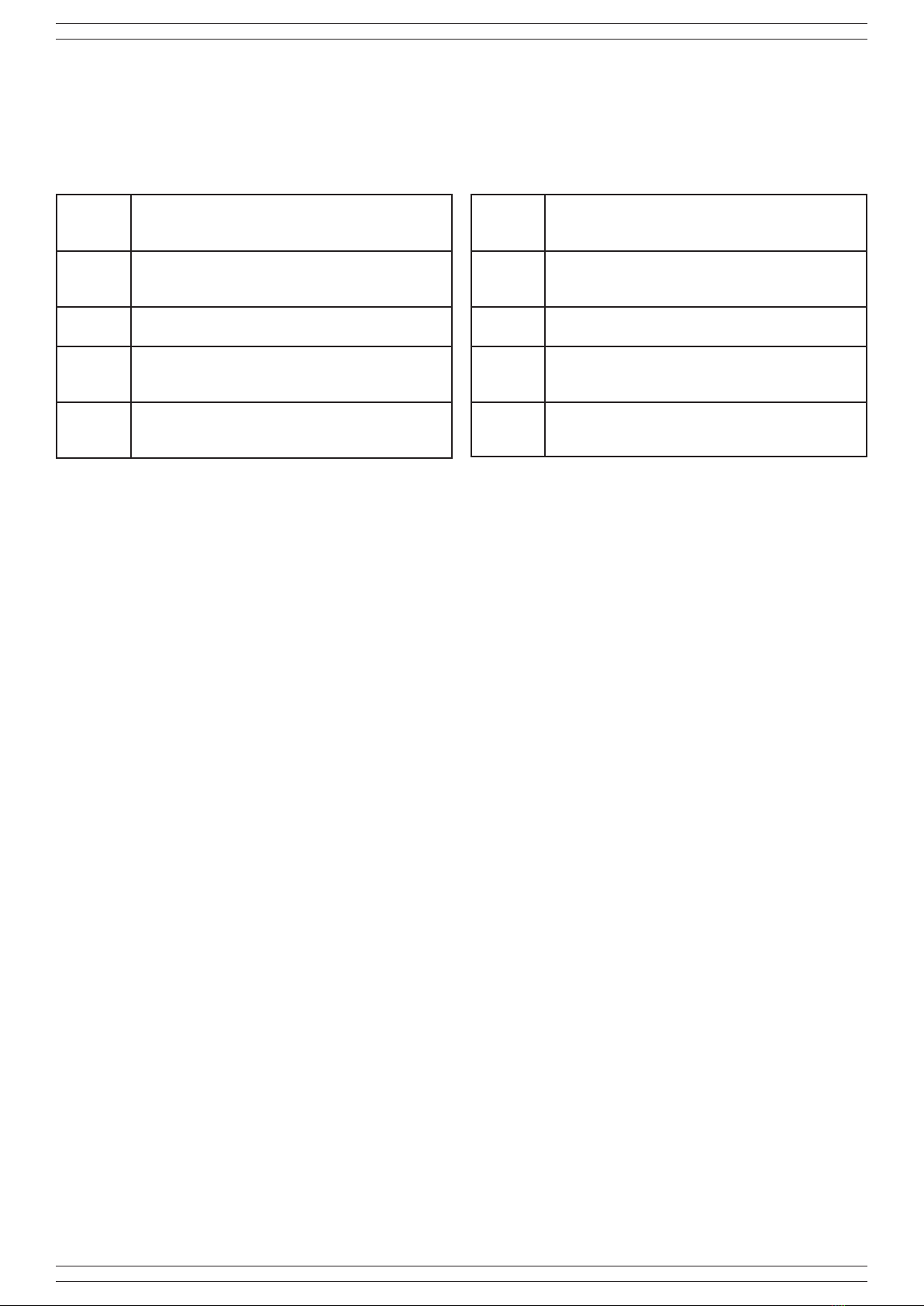
fare riferimento alla seguente tabella:
WT Morsetto per l’esclusione a distanza dei LED di
allarme e abilitazione memoria (vedi paragrafo
Esclusione LED ed abilitazione memoria).
AS Contatti dello switch antisabotaggio Normalmente
chiuso.
Collegare questi morsetti alla linea antisabotaggio.
NC Contatti del relé di allarme Normalmente Chiuso.
Collegare ad una linea di allarme.
AC Contatto relè N.C. dell’antimascheramento.
Si apre quando il rilevatore attiva l’allarme
Antimask e Warning.
+ / - Morsetti di alimentazione 12V, 34mA, quando il
sensore viene alimentato impiega circa 60 s per
stabilizzarsi.
FUNZIONE DEI LED
LED giallo: Lampeggiante, la microonda sta rilevando del
movimento nell’ambiente
LED verde: Accesosso,ilsensoreinfrarossoharilevatouna
presenza
LED rosso: Accesosso,condizionediallarme.
ESCLUSIONE LED ED ABILITAZIONE MEMORIA
Il morsetto WT consente di escludere a distanza i led di allarme e
conseguentemente abilitare la memoria del sensore.
Per attivare questa funzione si deve inviare un positivo presente
ad impianto disinserito sul morsetto WT.
Incasodiallarme,ilrilevatorechelohageneratorimarràconil
LEDrossoaccesossonoall’inserimentosuccessivo.
N.B.: inserendo l’impianto con il sensore in allarme anche se
temporizzato,siattiveràlamemoria.
FUNZIONE AND/OR
In AND si ha l’allarme solo quando tutti e due i sensori rilevano la
causa, mentre in OR quando soltanto uno dei due si attiva.
FUNZIONE ANTIMASK
Ad impianto inserito, il rilevatore è operativo anche in caso di
accecamento del sensore infrarosso dopo 5 preallarmi della
microonda.
FUNZIONE WARNING
Quando la funzione memoria è abilitata (positivo sul morsetto
WT), in caso di guasto o accecamento di una delle due
tecnologie, il microprocessore, dopo 50 rilevazioni di un sensore
(o microonda o infrarosso) senza che l’altro rilevi alcun allarme,
esclude automaticamente il sensore che non risponde.
L’anomaliaverràsegnalataconl’aperturadelloscambioACedil
lampeggio del led corrispondente alla tecnologia guasta.
NOTA: Se si toglie il positivo dal WT il rilevatore ripristina la
visualizzazione dei led dopo circa 15÷20 secondi.
CONNECTIONS
Connections with the 8028-ISR020 detector must be performed
with shielded cable: connect the shield to the control panel earth,
leaving it unconnected on the detector side.
Ifthedistancebetweendetectorandcontrolpanelissignicant,
ensure there is no voltage drop. Refer to the following table for a
description of terminals:
WT Terminal block for remotely disabling alarm LEDs,
and enabling memory (see paragraph LED disable
and memory enable paragraph).
AS Anti-tamper switch contacts Normally closed.
Connect these terminal blocks to the anti-tamper
line.
NC Alarm relay contacts Normally closed:
Connect to an alarm line.
AC N.C. anti-masking relay contact. It opens when
the detector activates the Antimask and Warning
alarm.
+ / - 12V, 34mA power supply terminal blocks, when the
sensor is powered it takes about 60 s to stabilise.
LED FUNCTION
Yellow LED: Flashing, the microwave is detecting motion in the
room
Green LED: Steady on, the infrared sensor has detected a
presence
Red LED: Steady on, alarm condition.
LED DISABLE AND MEMORY ENABLE
The WT terminal block remotely disables alarm LEDs and
consequently enables sensor memory. To activate this function
a positive signal present if the system is disarmed, must be sent
to WT terminal block.
In the event of an alarm, the detector that has triggered it will
remain with red LED steady on until the next input.
Note When the system is switched on with sensor in alarm even
if timed, the memory will be enabled.
AND/OR FUNCTION
In AND the alarm is triggered only when both sensors detect the
cause, whereas in OR when only one of the two is activated.
ANTIMASK FUNCTION
With system on, the detector is operative even in case of infrared
sensor blinding after 5 microwave pre-alarms.
WARNING FUNCTION
When the memory function is enabled, (positive signal on WT
terminal block), in the event of fault or blinding of one of the
two technologies, after 50 detections by a sensor (microwave
or infrared) without any alarms being detected by the other, the
microprocessor automatically overrides the sensor that does not
respond. The fault will be signalled by AC switch opening and the
LEDcorrespondingtothefaultytechnologyashlighting.
NOTE. If positive signal is removed from WT the detector
restores LED display after about 15÷20 seconds.