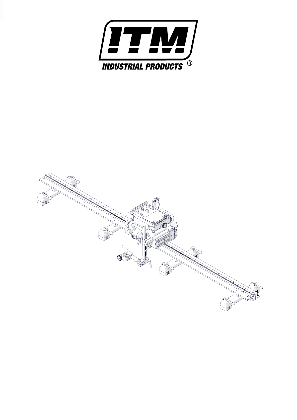
RAIL TITAN OPERATOR’S MANUAL
2www.itmtools.com.au
LIMITED WARRANTY
Industrial Tool & Machinery Sales (hereinafter referred to as ITMS) will, within twelve (12) months from the original date of purchase, repair
or replace any goods found to be defective in materials or workmanship.
This warranty is void if the item has been damaged by accident, neglect, improper service or other causes not arising out of defects in
materials or workmanship. This warranty does not apply to machines and/or components which have been altered, changed, or modified in
any way, or subjected to overloading or use beyond recommended capacities and specifications. Worn componentry due to normal wear
and tear is not a warranty claim. Goods returned defective shall be returned prepaid freight to ITMS or agreed repair agent, which shall
be the buyer’s sole and exclusive remedy for defective goods. ITMS accepts no additional liability pursuant to this guarantee for the costs
of travelling or transportation of the product or parts to and from ITMS or the service agent or dealer, such costs are not included in this
warranty.
Our goods come with guarantees which cannot be excluded under the Australian Consumer Law. You are entitled to replacement or refund
for a major failure and to compensation for other reasonably foreseeable loss or damage. You are also entitled to have the goods repaired or
replaced if the goods fail to be of acceptable quality and the failure does not amount to a major failure.
THE MANUFACTURER RESERVES THE RIGHT TO MAKE IMPROVEMENTS AND MODIFICATIONS TO
DESIGN WITHOUT PRIOR NOTICE.
PRODUCTS IMPORTED AND DISTRIBUTED NATIONALLY BY:
INDUSTRIAL TOOL & MACHINERY SALES
18 BUSINESS ST, YATALA QLD 4207
F: 07 3287 1115 W: www.industrialtool.com.au
Contents
1. GENERAL INFORMATION ............................................................................................... 3
1.1. Application ................................................................................................................. 3
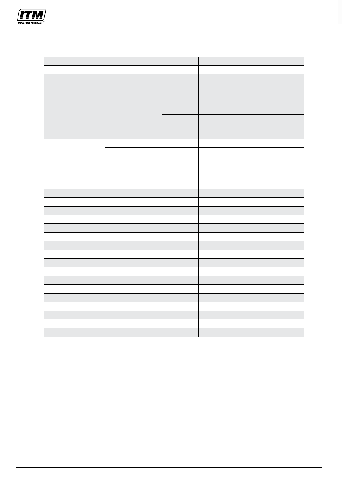
1.2. Technical data............................................................................................................ 4
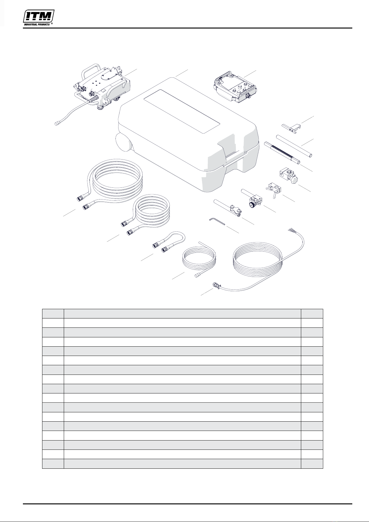
1.3. Equipment included ................................................................................................... 5
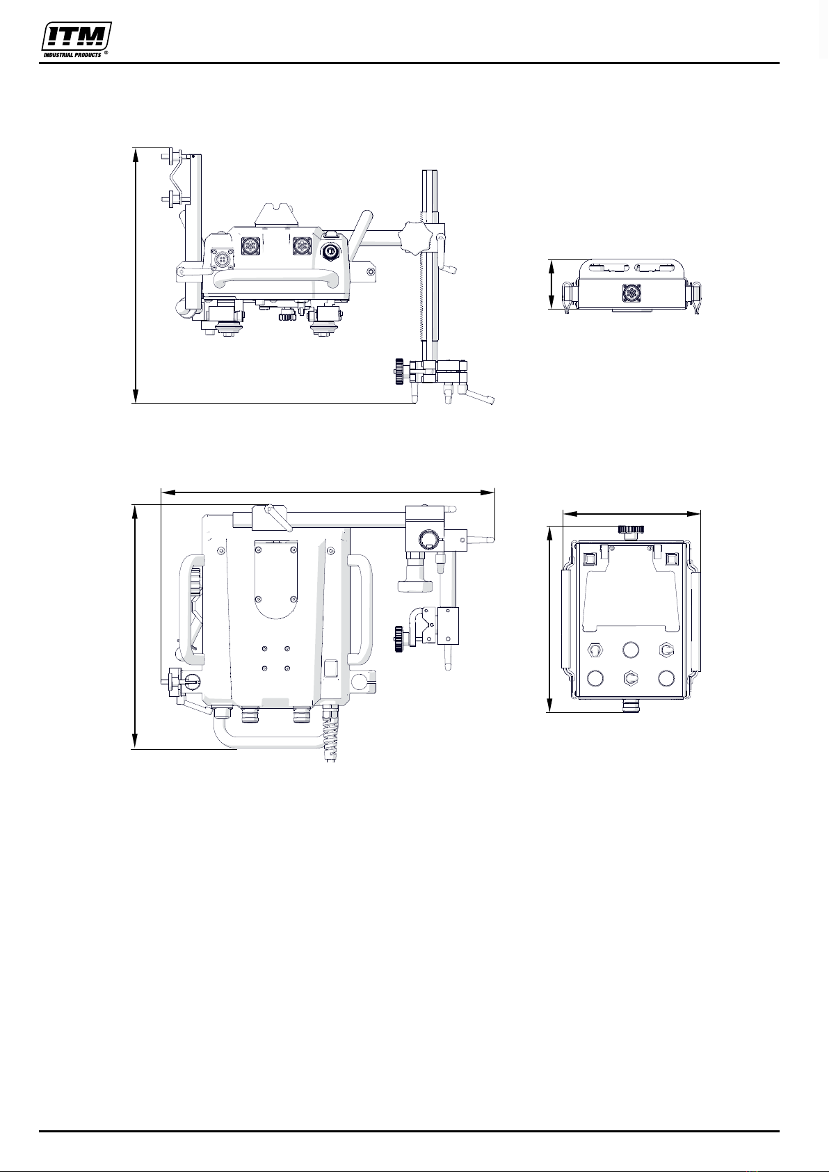
1.4. Dimensions ................................................................................................................ 6
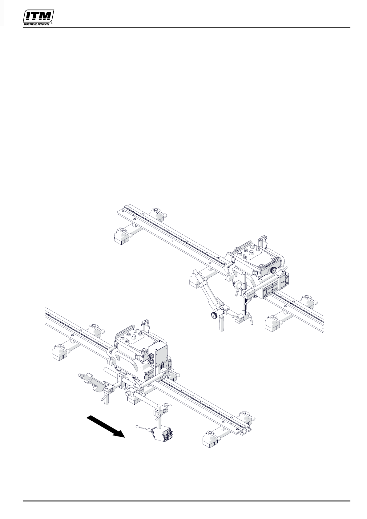
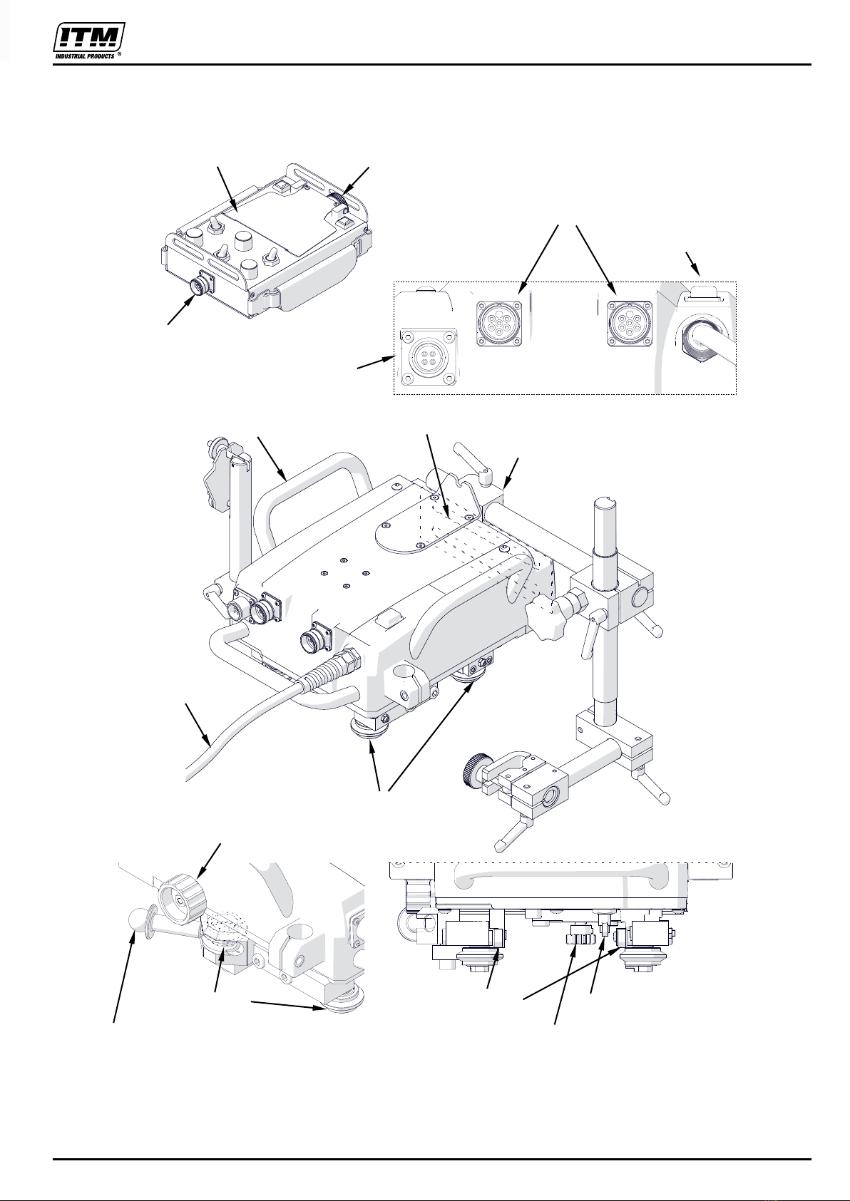
1.5. Design ....................................................................................................................... 7
2. SAFETY PRECAUTIONS.................................................................................................. 8
3. STARTUP AND OPERATION ..........................................................................................10
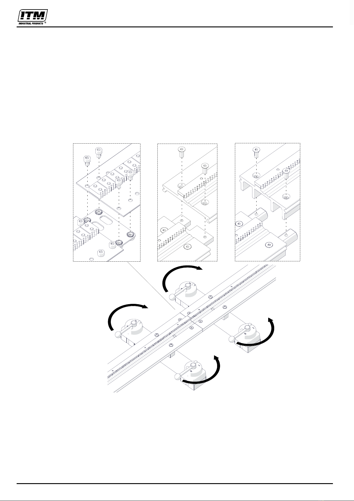
3.1. Assembling the hi-flex, semi-flex, or rigid track..........................................................10
3.2. Assembling the ring track..........................................................................................12
3.3. Positioning on a straight track ...................................................................................14
3.4. Positioning on a curved track ....................................................................................16
3.5. Preparing and connecting .........................................................................................17
3.6. Connecting to the welding circuits.............................................................................18
3.7. Operating ..................................................................................................................19
3.8. Adjusting the pressure of rollers................................................................................25
3.9. Adapting for seam tracking (option)...........................................................................26
3.10. Troubleshooting ......................................................................................................30
4. MAINTENANCE ...............................................................................................................31
5. ACCESSORIES ...............................................................................................................32
5.1. Seam tracking attachment.........................................................................................32
5.2. Tracking sensor tips ..................................................................................................32
5.3. Motorized vertical slide..............................................................................................33
5.4. Cables ......................................................................................................................33
5.5. Hi-flex track...............................................................................................................34
5.6. Semi-flex track ..........................................................................................................35
5.7. Rigid track.................................................................................................................35
5.8. Rack adjustment tool.................................................................................................35
5.9. Contact block ............................................................................................................36
5.10. Magnetic units.........................................................................................................37
5.11. Semi-flex track support............................................................................................42
5.12. Vacuum track system..............................................................................................43
5.13. Ring tracks ..............................................................................................................44
5.14. Ring track supports and bracket..............................................................................46
5.15. Torch holders, clamps, and rods .............................................................................47
5.16. Transport attachment ..............................................................................................49
5.17. Pendulum oscillator.................................................................................................50
6. PARTS BREAKDOWN.....................................................................................................52
7. ELECTRICAL DIAGRAM..................................................................................................60