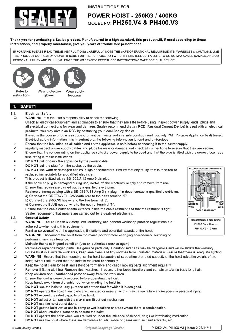
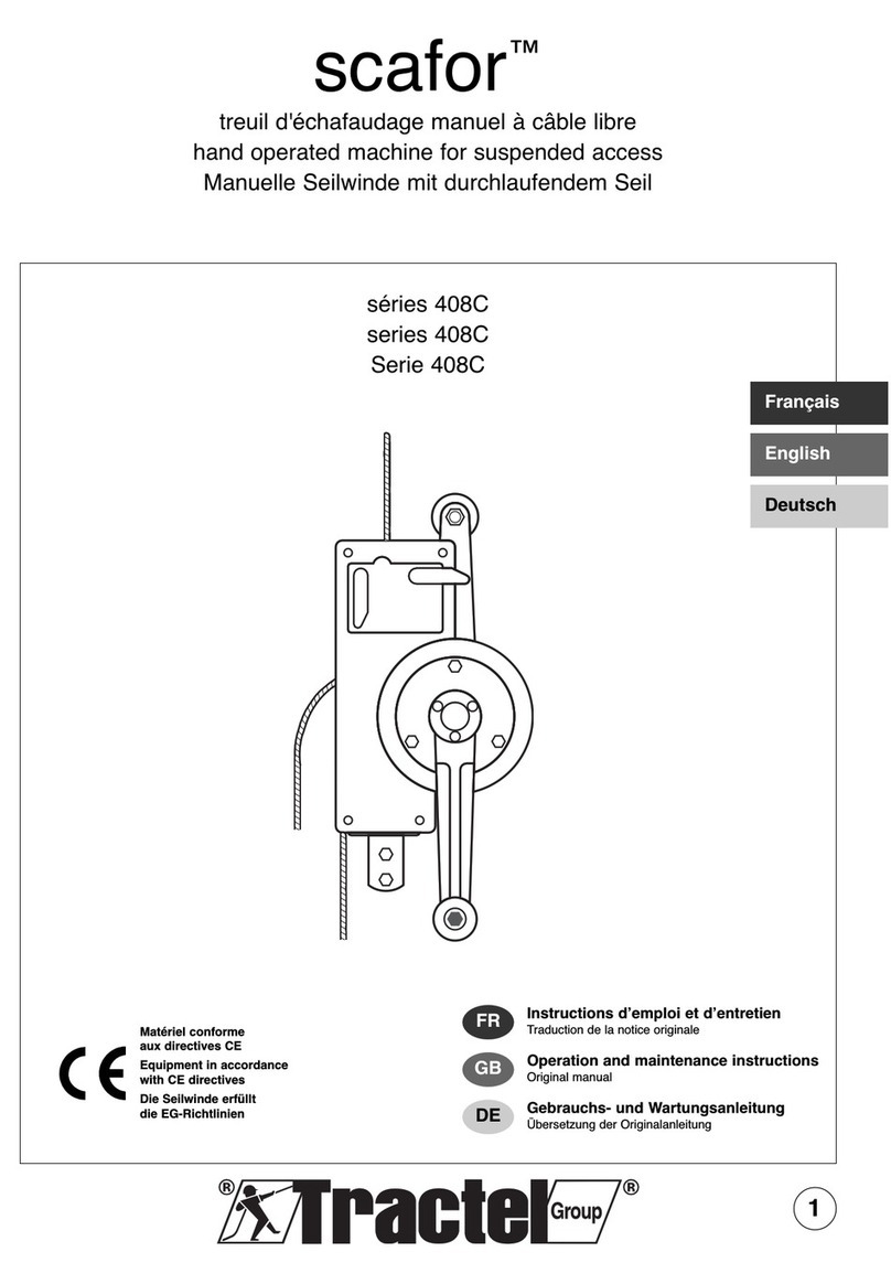
J. D. NEUHAUS PROFI 3 Ti User manual

JDN OPERATION MANUAL
AIR HOISTS
,, ,
16
10
6
3

Page 2
This manual edition 07/2003, covers the following
JDN Air Hoists:
Before operating any hoist, carefully read the entire
manual. For hoists mounted in trolleys, refer also to the
JDN Trolleys Operation Manual.
Please enter the Fabr. No. of your JDN Air Hoist here.
Fabr. No. Fabr. No.
Fabr. No. Fabr. No.
3
6
10
16

Page 3
TABLE OF CONTENTS
Organisational measures . . . . . . . . . . . . . . . . . . 5
Personnel safety . . . . . . . . . . . . . . . . . . . . . . . 5
Preventing property damage . . . . . . . . . . . . . . . 5
The operation manual . . . . . . . . . . . . . . . . . . . . 6
Warnings and symbols . . . . . . . . . . . . . . . . . . . 6
Designation . . . . . . . . . . . . . . . . . . . . . . . . . . . 7
Assembly overview . . . . . . . . . . . . . . . . . . . . . . 8
Product description . . . . . . . . . . . . . . . . . . . . . . 8
Explosion protection . . . . . . . . . . . . . . . . . . . . . 8
Intended use . . . . . . . . . . . . . . . . . . . . . . . . . 14
Operating conditions . . . . . . . . . . . . . . . . . . . . 14
Energy requirements . . . . . . . . . . . . . . . . . . . . 15
Principle of operation of
JDN air vane motors . . . . . . . . . . . . . . . . . . . . 16
Operation without chain box . . . . . . . . . . . . . . 17
Operation with service unit . . . . . . . . . . . . . . . 17
CE designation . . . . . . . . . . . . . . . . . . . . . . . . 17
Certification . . . . . . . . . . . . . . . . . . . . . . . . . . 17
Spare parts . . . . . . . . . . . . . . . . . . . . . . . . . . . 17
Safe transportation . . . . . . . . . . . . . . . . . . . . . 18
Storage conditions . . . . . . . . . . . . . . . . . . . . . 18
Unpacking . . . . . . . . . . . . . . . . . . . . . . . . . . . 19
Assembly . . . . . . . . . . . . . . . . . . . . . . . . . . . . 19
Installing the hoist . . . . . . . . . . . . . . . . . . . . . 19
Connecting the controls . . . . . . . . . . . . . . . . . . 20
Replacing controls . . . . . . . . . . . . . . . . . . . . . . 23
Connecting to the main air supply . . . . . . . . . . 25
Lubricants . . . . . . . . . . . . . . . . . . . . . . . . . . . 25
Checking prior to initial operation . . . . . . . . . . 26
Rules for safe operation of hoists . . . . . . . . . . . 27
Controls . . . . . . . . . . . . . . . . . . . . . . . . . . . . . 29
Emergency stop device . . . . . . . . . . . . . . . . . . 31
Overload protection . . . . . . . . . . . . . . . . . . . . . 31
Attaching the load . . . . . . . . . . . . . . . . . . . . . 31
Lifting the load . . . . . . . . . . . . . . . . . . . . . . . 32
Lowering the load . . . . . . . . . . . . . . . . . . . . . . 32
Detaching the load . . . . . . . . . . . . . . . . . . . . . 32
Interrupting working . . . . . . . . . . . . . . . . . . . 32
Shutting down . . . . . . . . . . . . . . . . . . . . . . . . 33
Storage . . . . . . . . . . . . . . . . . . . . . . . . . . . . . 33
Dismantling . . . . . . . . . . . . . . . . . . . . . . . . . . 33
Disposal . . . . . . . . . . . . . . . . . . . . . . . . . . . . . 33
Maintenance and inspection intervals . . . . . . . . 34
Cleaning and care . . . . . . . . . . . . . . . . . . . . . . 34
Spare parts . . . . . . . . . . . . . . . . . . . . . . . . . . . 34
Lubricants . . . . . . . . . . . . . . . . . . . . . . . . . . . 34
Inspection and repairs . . . . . . . . . . . . . . . . . . . 34
Checking braking function . . . . . . . . . . . . . . . . 37
Checking direction of movement . . . . . . . . . . . 37
Checking lifting and lowering limiters . . . . . . . 37
Checking emergency stop function . . . . . . . . . . 37
Lubricating the chain . . . . . . . . . . . . . . . . . . . 38
Checking controls . . . . . . . . . . . . . . . . . . . . . . 38
Checking the silencer for permeability . . . . . . . 38
Service unit . . . . . . . . . . . . . . . . . . . . . . . . . . 39
Replacing brake disc and brake piston . . . . . . . 42
Replacing vanes . . . . . . . . . . . . . . . . . . . . . . . 42
Motor installation, motor lubrication . . . . . . . . 42
Removing and installing load sleeve,
bottom block, clamp and buffer . . . . . . . . . . . . 44
Checking chain, chain sprocket and chain guides 46
Check dimensions . . . . . . . . . . . . . . . . . . . . . . 47
Checking axial play . . . . . . . . . . . . . . . . . . . . . 48
Removing and installing chain . . . . . . . . . . . . . 50
Replacing chain and chain sprocket . . . . . . . . . 51
Overload protection . . . . . . . . . . . . . . . . . . . . . 52
Fault table . . . . . . . . . . . . . . . . . . . . . . . . . . . 53
Filter silencer . . . . . . . . . . . . . . . . . . . . . . . . . 54
Booster unit . . . . . . . . . . . . . . . . . . . . . . . . . . 55
Chain box . . . . . . . . . . . . . . . . . . . . . . . . . . . . 55
Technical data . . . . . . . . . . . . . . . . . . . . . . . . . 56
Dimensions . . . . . . . . . . . . . . . . . . . . . . . . . . 57
APPENDIX
ACCESSORIES
FAULTS, CAUSE AND REMEDY
MAINTENANCE
TAKING OUT OF OPERATION
OPERATION
INITIAL OPERATION
TRANSPORT AND STORAGE
PRODUCT INFORMATION
SAFETY INSTRUCTIONS

Please note!
Within the Federal Republic of Germany operators of
air hoists must comply with
UVV Winches, Lifting and pulling Devices (BGV D8)
and UVV Load-carrying Devices used with Lifting
Equipment (VBG 9a)
and, for air hoists installed in trolleys, additionally with
UVV Cranes (BGV D6)
in the respective currently applicable version. Operators
must also initiate the prescribed tests (see also
"Principles for the Testing of Cranes" BGG 905 (ZH1/27).
In all other countries, the operator shall comply with
local regulations as applicable.
Special regulations may apply when incorporating air
hoists into other installations or using air hoists under
unusual conditions.
Page 4

JDN Air Hoists are designed in accordance with current
technological standards and accepted safety practice.
Nonetheless, the use of an air hoist may be associated
with risk of injury or fatality to the user or to third
parties or with the risk of damage to the hoist or to
other items.
All personnel charged with operating air hoists, must
have read and understood the operation manual, especi-
ally the section concerning safety instructions, before
commencing work. This is particularly important for
personnel who only occasionally operate the hoist,
e.g. for maintenance or retrofitting work.
Operators of JDN Air Hoists are also under obligation
to ensure safe and hazard-free operation. This can be
achieved through the following measures:
the operation manual must always be kept available
at the hoist operating site,
performing regular training,
implement an inspection log and make regular entries,
and regularly check personnel for safety and hazard
awareness during work.
Personnel who operate, maintain, inspect and perform
setting-up work on the hoist must be properly trained
or must receive an introduction from properly trained
personnel, before commencing work.
Due to their technical training and experience, properly
trained personnel have adequate knowledge of hoists.
They are sufficiently familiar with the relevant occupa-
tional safety and accident prevention regulations, that
they are able to assess the condition of hoists, with
regard to working safety.
Follow the operating instructions for your workplace.
Observe the accident prevention regulations,
especially BGV D8 (Winches, Lifting and Pulling
Devices) and VBG 9a (Load-carrying Devices used with
Lifting Equipment).
Ensure that you are properly informed regarding
working with hazardous materials.
Follow the safety instructions set out in this
operation manual.
Operators of JDN Air Hoists are under obligation to
ensure that entries in the accompanying inspection log
are made properly and regularly.
Comply with the prescribed maintenance intervals.
Only use JDN Air Hoists for work which is described
as intended use.
Observe the operating conditions for hoists as
described in this manual.
PREVENTING PROPERTY DAMAGE
PERSONNEL SAFETYORGANISATIONAL MEASURES
SAFETY INSTRUCTIONS
SAFETY INSTRUCTIONS
Page 5

This operation manual is intended to help the operator
familiarise himself with JDN Air Hoists and to take full
advantage of their designated areas of application.
This operation manual contains important information
for the safe, proper and economic operation of JDN Air
Hoists. Observance of the manual helps to avoid hazar-
dous situations, to reduce repair costs and downtimes
and to extend the service life of the JDN Air Hoists.
Safety warnings in this operation manual are classified
in three categories.
DANGER!
Safety warning, which if not followed can
result in a hazard to life and limb, are indi-
cated by this symbol.
The symbol indicates an immediate danger.
The possible consequences of non-observance
may be severe or even fatal injuries.
CAUTION!
This symbol indicates situations, which
may become hazardous. Failure to observe
may result in light injuries.
ATTENTION!
This symbol indicates that failure to follow
instructions may result in damage to the
device or other equipment.
WARNINGS AND SYMBOLSTHE OPERATION MANUAL
PRODUCT INFORMATION
PRODUCT INFORMATION
Page 6

The nameplate mounted on the housing cover identifies
the type of JDN Air Hoist and contains all important
rating data.
If you have any questions concerning operation of JDN
Air Hoists, which are not addressed in this operation
manual, please contact us at the following address:
J.D. NEUHAUS GMBH & CO. KG
Windenstra§e
D - 58449 Witten-Heven
Phone + 49 - 23 02 - 20 80
Fax + 49 - 23 02 - 20 82 86
http://www.jdn.de
e-mail: info@jdn.de
Example of nameplate on housing cover
DESIGNATION
PRODUCT INFORMATION
Page 7

series air hoists consist of the following
assemblies:
1Gearbox with chain sprocket and overload protection
2Centre section
3Motor with integral brake function
4Controls with main air EMERGENCY STOP
5Chain
6Load hook with load sleeve or bottom block and buffer
The series JDN Air Hoists described here are
designed for load-carrying capacities from 3.2 t
()
to 16 t ()
. Various control
devices are available for the different requirements.
The air vane motor of the hoist, together with the
appropriate controls, is capable of sensitive movement.
This enables precise positioning of the load.
series JDN Air Hoists conform to driving
mechanism classification M3/1Bm, ISO 4301/FEM 9.511.
JDN Air Hoist motors feature rotors with
grease chambers. This contains JDN high-performance
grease, which enables operation with oil-free compressed
air. It remains effective for an operating period of
approx. 250 hours and should be renewed after five
years, at the latest (see Motor lubrication, page 43).
Additional lubrication with oil-bearing compressed air
by means of a service unit with oiler is possible.
The basis for the following information is an expert
statement by the DMT Gas & Fire Division on the use
of JDN Hoists, Trolleys and Crane Systems in explosion-
hazardous areas, based upon European Guideline
94/9/EC1("ATEX 100a"). DMT is accredited with the
testing of devices and protection systems for intended
use in explosion-hazardous areas.
series JDN Air Hoists
BASIC EXPLOSION PROTECTION
OF THE STANDARD VERSIONS
Standard version JDN Air Hoists are category 2 devices
(Guideline 94/9/EC, DIN EN 1127-12), for use in zone 1
and 2 for gases of explosion group IIA. (see also IEC
60079-123and IEC 60079-204). These devices are also
suitable for use in zone 2, in the presence of gases of
explosion group IIB, provided that the substances
hydrogen sulphide and ethylene oxide can be excluded
and additionally in zones 21 and 22 for dusts with glow
temperatures above 210¡C and ignition temperatures
above 202¡C, provided that no light metal or other
impact-sensitive dusts are present. In zones 1 and 21,
friction and impacts in the working area of the chain
must be excluded.
These devices are designated by:
.
32
4
6
5
1
2
3
EXPLOSION PROTECTION
16
3
PRODUCT DESCRIPTION
ASSEMBLY OVERVIEW
PRODUCT INFORMATION
Page 8

ADDITIONAL MARKING "X"
or
: This designation does not permit
use in the presence of the extremely flammable sub-
stances hydrogen sulphide and ethylene oxide or in the
presence of light metal or other impact-sensitive dusts,
or in the presence of dusts with glow temperatures
below 210°C and ignition temperatures below 202°C.
: This designation permits use in the
presence of carbon disulphide or other temperature
class T6 substances only under special conditions, which
have been agreed with the manufacturer and which are
described in the crane documentation (Europe: in the
inspection log) and which stipulate the maximum surface
temperatures for the device.
GENERAL NOTE ON DESIGNATION
The highest possible respective designations for lifting
equipment and running gear are usually replaced by a
designation, which corresponds to the normal assembly
of a compact complete device (trolley or crane system).
JDN HOISTS
"WITH INCREASED SPARK PROTECTION"
JDN Hoists in the "with increased spark protection"
version (SP), fulfil further explosion protection require-
ments. With the exception of carbon disulphide, they
can be used in the presence of all gases in zones 1 and
2 and dusts with glow temperatures above 210°C and
ignition temperatures above 202°C and can be designated
with for installation in a trolley,
depending upon trolley version (see below), but also
with . For further operating conditions,
see Instructions for safe operation (Notes and ).
JDN HOISTS FOR USE IN THE PRESENCE OF
TEMPERATURE CLASS T6 GASES OR EXTREMELY
EXPLOSIVE DUSTS
Following separate tests, especially with regard to
ambient temperatures and type of operation, use in the
presence of carbon disulphide or dusts with particularly
low glow or ignition temperatures may be possible with
designation , which includes the
additional marking "X" for special conditions
(see Additional marking "X").
Please contact us with regard to these requirements.
MATERIALS FOR FRICTION AND IMPACT HAZARDS
The combination of particular material pairs results in
an increased ignition hazard. This does not apply to
corrosion-resistant steel or cast iron against aluminium,
magnesium or corresponding alloys.
It applies in particular to the presence of rust or of rust
film. Rust (also rust film) formation is possible, especi-
ally on the chain and on the load hook, at the friction
points. In zones 1 and 21, but also in zone 2 for gases
of explosion group IIC, hydrogen sulphide and ethylene
oxide, as well as in zone 22 for light metal and other
impact-sensitive dusts, the following generally applies:
For the intended use of hoists it must be ensured, that
no rust is present at the above-mentioned friction
points and that material combinations of the above-
named light metals with steel (exception: stainless
steel) are not used in the working area of the hoists, at
potential friction, impact or sliding points. It is thus
possible to exclude sparking due to mechanical influen-
ces with these material combinations.
COMPRESSED AIR HOSES
In zone 1, compressed air hoses must have a sufficiently
low surface resistance of less than 109Ω, in order to
prevent electrostatic ignition hazards. Otherwise
(resistance >109Ω), for explosion groups IIA and IIB
the hoses must be ∅≤30 mm and for explosion group
iic ∅≤20 mm, or proof must be provided that they
cannot become dangerously charged.
ED
... IIC T6(X)
II 3 GD IIA T4(X)
PRODUCT INFORMATION
Page 9

ACETYLENE AND COPPER
When operating JDN products in explosion-hazardous
areas, in which an acetylene-containing atmosphere can
occur, it must be ensured that copper-plated parts are
kept dry, in order to exclude the possibility of oxidation
of the metallic copper and the formation of a watery
phase, which is capable of reacting with acetylene and
which can result in an explosion hazard.
EARTHING
Electrostatic ignition hazards can be prevented by
means of safe earthing. In zones 1 and 21, earthing of
the hoists is required. This must be achieved via the
load hook or the load eyes, if the lifting equipment is
connected to correspondingly earthed parts (earth lea-
kage resistance less than 106Ω). This also applies to
operation with trolleys or cranes. Their tracks must be
earthed on site. Running wheels and rail surfaces must
never be painted, as this can result in unacceptably
high earth leakage resistance values.
Earthing of the load hook is via the chain (see also
"Load chain" below).
Loads must be earthed during transportation. A separa-
te earth is required, for example, when using non-con-
ducting sling gear.
LOAD CHAIN
In order to prevent mechanical sparking in zones 1 and
21, but also in zone 2 for gases of explosion group IIC,
hydrogen sulphide and ethylene oxide, as well as in
zone 22 for light metal and other impact-sensitive
dusts, the chain and the load must always be moved in
such a way, that sliding or frictional contact with other
plant and components is excluded.
In order to guarantee the required degree of earthing,
rusty chains must no longer be used in zones 1 and 21.
As, depending upon the degree of corrosion, the leakage
capability of the chain may be impaired to a level that
is no longer adequate.
PRODUCT INFORMATION
Page 10

PRODUCT INFORMATION
Page 11
( ): The measured values for the substances placed in brackets are close to the limit of the next group of class when classified
in the explosion groups or temperature classes. For this reason, they have been included in both.
**: Extremely flammable substances (cf. additional marking "X")
*1 (Methanol = Methyl alcohol)
Ex group Temperature class
T1 T2 T3 T4 T5 T6
Ignition temperature
> 450°C 450-300°C 300-200°C 200-135°C 135-100°C 100-85°C
Maximum permissible surface temperature of operating facilities
450°C 300°C 200°C 135°C 100°C85°C
II A Acetone (Ethyl alcohol) n-Amyl alcohol Acetaldehyde
Ammonia (Ethylene glycol) Benzene
Aniline i-Amyl acetate (petrol)
Benzol n-Butane Diesel
Chlorobenzene n-Butyl alcohol Fuel oil
1,2-Dichlorobenzene 1-Butylene n-Hexane
Acetic acid 1,2-Dichloroethane jet fuels
Ethane Di-i-Propyl ether
Ethyl acetate Natural gas
(Ethyl bromide) Acetic anhydride
Ethyl chloride n-Propyl acetate
(Carbon monoxide) (n-Propyl alcohol)
o-Cresol i-Propyl alcohol
Methane Vinyl chloride
Methyl acetate
Methyl alcohol*1
Methyl bromide
Methyl chloride
Methylene chloride
Naphthaline
(Nitrobenzene)
Phenol
Propane
Toluene
o-Xylene
II B Hydrocyanic acid Butadiene-1,3 Dimethylether Ethyl ether
(Ethyl bromide) Dioxane-1,4 **Hydrogen Ether
(carbon monoxide) Divinyl ether sulfide Anaesthetic ether
(Nitrobenzene) (Ethyl alcohol) Diethyl ether
Town gas Ethylene
(Ethylene glycol)
**Ethylene oxide
Isoprene
(n-Propyl alcohol)
II C **Hydrogen **Acetylene **Carbon
disulphide
EXPLOSION GROUPS AND TEMPERATURE CLASSES OF THE MOST IMPORTANT GASSES AND VAPOURS ( SELECTION )
(according to DIN VDE 01655, Redeker6, Nabert, Schön7, IEC 60079-123and IEC 60079-204)

PRODUCT INFORMATION
Page 12
*1: Features:
A: The chain is made of zinc-plated steel; metal controls are conductively connected to the hoist. This is part of
the standard equipment. For technological reasons, a zinc-plated version of chain size 31.5 x 90 is not available.
This is only used for the extremely slow-running chain drives of large hoists, so that the sliding velocity for
potential friction points between the chain and the surroundings remains well below 1 m/s.
SP: Hoists "with increased spark protection":
Copper-plated load hook and bottom block with brass safety catch.
FSR: Running gear "with increased spark protection":
Running wheels for trolleys and cranes are bronzed or are made of bronze.
*2: Instructions for safe operation:
: Ignition hazards are not to be expected if hoists or cranes are used in the normal manner. Friction and impacts in
the working area of the chain, not resulting from intended use of the hoist or crane and which result in sparking,
must be excluded. This applies in particular to use in conjunction with light metals or light metal alloys.
(exception: stainless steel)
: A gas-free or spark-free environment must be ensured in the working area. This means, for example, that the
chain, the bottom block and the load hook must be prevented from swinging against surrounding objects or that a
gas-free environment must be ensured.
: Ambient temperature and the type of operation must be examined separately. Equipment surface temperatures are
dependent upon the type of operation and the ambient temperature.
Therefore, separate testing is required for materials of the temperature classes T5 and T6.
A maximum ambient temperature of 40°C is a pre-condition for the specification of temperature class
(see also EN 500148).
T
E
D
DECISION CRITERIA FOR SELECTING THE CORRECT JDN HOISTS IN EXPLOSION HAZARDOUS AREAS
Explosion groups of gases and vapours Zone Version*1Operation*2
(cf. Explosion groups and temperature classes of the most important gasses and vapours)
II A 2 A
1A
II B (X) except hydrogen sulphide, ethylene oxide 2A
(particularly flammable) 1AFS
II B 2 A FS
1AFS
II C / T4 2 A FS
1 A FS FSR
II C / T6(X) 2 A FS
1 A FS FSR
Explosion-hazardous dusts Zone Version*1Operation*2
Usual industrial dusts 22 A
21 A
Light-metal or impact-sensitive dusts 22 A FS
21 A FS D
D
D
TED
TED
ED
ED
ED
ED
D
D

PRODUCT INFORMATION
Page 13
TEMPERATURE LIMIT FOR
EXPLOSION HAZARDOUS DUSTS
In areas which are explosion-hazardous due to combu-
stible dusts, the surface temperature must not exceed
two-thirds of the ignition temperature in °C of the
dust/air mixture. The temperatures of surfaces on which
hazardous deposits of combustible dusts can be formed,
must not exceed the glow temperature of the relevant
dust minus 75°K. Greater safety margins are required if
thickness of the dust layer exceeds 5 mm.
The corresponding surface temperatures can be derived
from the lowest values for glow and ignition tempera-
tures of dusts specified in the HVBG/BIA Report 12/979
"Combustion and explosion characteristics of dusts":
Synthetic rubber, soot-containing:
Glow temperature 220°C - 75°C = 145°C
max. permissible
surface temperature
Stearic acid:
Ignition temperature 190°C x 2/3 = 126°C
max. permissible
surface temperature.
PLEASE ALSO OBSERVE YOUR
CORRESPONDING NATIONAL REGULATIONS.
1Guideline 94/9/EC OF the European Parliament and the Council of 23 March 1994 on the approximation of the laws of
the Member States concerning equipment and protective systems intended for use in potentially explosive atmospheres
2DIN EN 1127-1: Explosive atmospheres - Explosion prevention and protection - Part 1: Basic concepts and methodology,
1997-10
3IEC 60079-12: Electrical apparatus for explosive gas atmospheres, Part 12: Classification of mixtures of gases and
vapours with air according to their maximum experimental safe gaps and minimum igniting currents, 1978.
4IEC 60079-20: Electrical apparatus for explosive gas atmospheres, Part 20: Data for flammable gases and vapours,
relating to the use of electric apparatus, 1996-10.
5DIN VDE 0165: Installation of electrical systems and equipment in areas with explosion hazard, 1991
6Nabert, Schön: Sicherheitstechnische Kennzahlen brennbarer Gase und Dämpfe 2nd edition, 1978
7Redeker, Schön: 6. Nachtrag zu Sicherheitstechnische Kennzahlen brennbarer Gase und Dämpfe, 1990
8DIN EN 50014 (VDE 0170/0171 part 1): 2000-02
Electrical apparatus for use in explosion hazardous areas: General provisions
9HVBG/BIA-Report 12/97: Central association of German employer's liability associations/Trade association institute
for industrial safety

PRODUCT INFORMATION
Page 14
JDN Air Hoists are designed for lifting and
lowering loads within the specified load-carrying capa-
cities, with a vertically-arranged chain. They are also
suitable for pulling loads horizontally. Under certain
conditions, the lifting of personnel-carrying equipment
is also permitted.
In combination with trolleys, JDN Air Hoists are also
suitable for the floorless horizontal movement of loads.
Any other use or use outside these stipulations is
deemed to be abnormal. Oblique pulling, see section
Operation, page 27. J.D. NEUHAUS GMBH & CO. KG
cannot be held liable for any resulting damage.
The entire risk is borne by the user (see also section
Rules for safe operation of hoists, page 27).
Intended use also includes observance of the operation
manual and compliance with the inspection and mainte-
nance conditions.
JDN Air Hoists are extremely robust and require little
maintenance. They are suitable for use in explosion-
hazardous areas, as well as in areas with increased
concentrations of soot and dust, high humidity and at
temperatures of -20°C up to approx. +70°C.
The thermal endurance of chains and hooks is +150°C.
CAUTION!
When touching metallic hand controls which
are colder than 0°C, freezing of the skin can
occur within a few seconds and for tempera-
tures above 43°C, burns can occur.
For stationary outdoor operation, hoists must be protec-
ted against weathering and the maintenance intervals
must be shortened.
Depending upon the version, JDN Air Hoists must be
operated at a system pressure of 4 bar or 6 bar. If the
system pressure is too low, important functions of the
hoist will be impaired:
The brake will drag and is thus subject to a high
degree of wear.
DANGER!
Warning against excessive system pressures
Operating with excessive system pressures
results in danger due to overloading.
Therefore, the pressure must be limited to
that specified on the nameplate.
JDN Air Hoists must be operated with a sufficiently
clean and dry air supply. The air supply must fulfil the
following quality requirements:
Particle size less than 40 µm
Particle density less than 5 mg/m3
In order to provide adequate compressed air quality,
operation with a service unit is recommended. Usually,
an oiler is not required in the service unit, as the motor
is provided with internal permanent lubrication.
Pressure dew point at least 10°C below the lowest
expected ambient temperature
Do not operate JDN Air Hoists with other gases.
With moist air and ambient temperatures at or below
0°C, there is a danger of icing in the motor.
Icing can be prevented by:
the use of an upstream air dryer or using a service
unit with oiler,
adding anti-icing agent to the lubrication oil
(depending upon moisture content of compressed air)
or using compressed air oil (Art. no. 11900) with
anti-icing agent for relevant temperatures.
In case your JDN Air Hoist is operated in combination
with a trolley, please read also the trolley operation
manual and the relevant accident-prevention regulations
for operation with trolleys.
OPERATING CONDITIONS
INTENDED USE

PRODUCT INFORMATION
Page 15
For air pressure, air quantity and connections, see the
table Technical data, page 56.
AIR PRESSURE CONDITIONS IN OPERATION
The system pressure in the air line must correspond to
the nominal pressure. Higher pressures must be reduced.
After switching on, the nominal pressure p1 drops to
the actual pressure p2.
The value of the actual pressure p2 at which the hoist
is operated, depends upon
the weight of the load and
the direction of movement of the load.
When lifting the nominal load (load-carrying capacity),
the actual pressure p2 must not fall below a value 10%
below the specified nominal pressure of the hoist.
Example:
A hoist with a nominal pressure of 6 bar lifts
its nominal load at the specified lifting speed, at an
actual pressure of 5.4 bar.
... the weight of the load ...
... and the direction of movement of the load.
The value of the actual pressure depends upon ...
ENERGY REQUIREMENTS

The vane motor consists of a cylinder liner 1with two
side bearing plates and an internal rotor 2.
The rotor is mounted eccentrically in the cylinder liner
and is provided with slots 3for installation of the vanes 4.
The vanes can move freely and make contact with the
inner wall 5of the cylinder liner. Each chamber is formed
by two vanes 6.
Due to the incoming compressed air, a greater force is
created at the leading, larger vane surface 4.1 than that
at the trailing, smaller vane surface 4.2. The difference
in force generates the rotor torque.
As the chamber passes the outlet aperture 7, the com-
pressed air can escape.
Lubricant chambers 8 are provided between the vane
slots of the rotor. They ensure continual motor lubri-
cation over a period of 250 - 500 operating hours
(depending upon motor type).
The arrows in the illustration indicate the direction of
rotation of the rotor and the corresponding path of the
compressed air.
4.2 164.1 2 5
3
847
PRINCIPLE OF OPERATION
OF JDN AIR VANE MOTORS
PRODUCT INFORMATION
Page 16

PRODUCT INFORMATION
Page 17
DANGER!
If JDN Air Hoists are operated without a
chain box, it must be ensured that the idle
chain (unloaded chain end) running up or
down at the chain sprocket, does not present
a hazard, e.g. due to catching, impacting or
falling.
Danger due to falling chain can also arise, if
the idle chain is first deposited on a load with
a large surface and then slides off and drops.
JDN Air Hoists are provided with motor lubrication,
which is sufficient for approx. 250 operating hours.
Therefore, the service unit for filtration and pressure-
regulation of the compressed air can be installed without
an oiler. If required, the service unit is also available
with an oiler.
Only hoists which have a designation
may be operated within the EU.
Each JDN Air Hoist is delivered with a factory certificate.
Only use original JDN spare parts. J.D. NEUHAUS
GMBH & CO. KG accepts no liability for the use of
non-original components and/or modifications by
unauthorised persons.
SPARE PARTS
CERTIFICATION
DESIGNATION
OPERATION WITH SERVICE UNIT
OPERATION WITHOUT CHAIN BOX

TRANSPORT AND STORAGE
Page 18
TRANSPORT AND STORAGE
If you wish to transport your JDN Air Hoist to another
site, please observe the following points:
Set the housing down carefully; do not allow to drop.
Weight of hoist, see Technical data, page 56.
Lay control and supply hoses together in such a way
that they are not kinked.
Secure the chain.
BREAKS IN OPERATION
In the case of longer operational breaks, coat the
chain and hook with a light oil film.
Motor conservation
If the grease packing of the rotor is not renewed after
250 operating hours, the motor must be conserved.
For this purpose, use a non-resinous and non-sticky
conserving oil with conserving protection duration,
which corresponds to the length of the planned ope-
rational break.
STORAGE
Close off the air supply hose connection using
adhesive tape or a suitable cap, in order to prevent
dirt ingress.
Store your JDN Air Hoist in a clean and dry place.
STORAGE CONDITIONS
SAFE TRANSPORTATION

INITIAL OPERATION
Page 19
INITIAL OPERATION
CAUTION!
When unpacking, take account of the weight
of the hoist. See Technical data, page 56.
ATTENTION!
Do not kink the control lines. Kinked
control lines can result in malfunctions.
Keep the accompanying documents in the place
provided, near the operating site.
Lift the hoist carefully out of the packaging.
Dispose of packaging in the local recycling system.
JDN Air Hoists are usually delivered pre-assembled.
If not, first read the following sections:
control connection (page 20)
Removing and installing chain (page 50)
Chain box (page 55)
In the case that the chain is included unattached, a
short auxiliary chain is drawn into the hoist. In order
to draw in the chain, the hoist must be connected to
the main air supply and must be ready for operation.
PRIOR TO INITIAL OPERATION,
THE CHAIN MUST BE LUBRICATED
(SEE PAGE 38).
DANGER!
JDN Air Hoists must only be installed
by qualified persons.
A defective installation can result in
the most serious of accidents.
DANGER!
The attachment points for JDN Air Hoists
must able to safely withstand the expected
forces.
DANGER!
The supporting structure of the air hoist
must form a rigid mounting. Vibration dama-
ges the chain and can lead to chain fracture.
Furthermore, external vibration must on no
account be transmitted to the hoist (lifting
gear). (e.g. from the suspended load).
Provide a suitable working platform.
Attach the hoist at the suspension hook (or suspensi-
on eye) to running gear or stationary fixing.
Ensure that the hook safety catch closes automatically.
Attach the hoist securely at the suspension hook
or suspension eye.
HOIST INSTALLATION
ASSEMBLY
UNPACKING

INITIAL OPERATION
Page 20
CONNECTING THE ROPE CONTROLS
Knot both control ropes at the ends of the
control lever.
Knot the green pin into the rope which activates
"lift" mode, with the pointed end upwards.
(See also illustration Rope control page 31)
Knot the yellow pin into the rope which activates
"lower" mode, with the pointed end downwards.
Knot the handle into the rope so that the arrow
markings correspond to the actual direction of
movement.
E-CONTROL CONNECTION
Pushbutton valve (hand control)
Guide the strain-relief rope through the eye on the
pushbutton valve and secure using the rope clamp.
Push the one-ear clamps onto the hose ends.
Attach the hoses to the hose nipples.
The one-ear hose clamp must lie in the middle of
the hose nipple clamping range. The best clamping
characteristics can be achieved in this range.
Pushbutton valve with nipples and rope with
designation lift and lower
Rope control, motor side
CONNECTING THE CONTROLS
Other manuals for PROFI 3 Ti
1
This manual suits for next models
3
Table of contents
Other J. D. NEUHAUS Chain Hoist manuals

J. D. NEUHAUS
J. D. NEUHAUS PROFI 3 Ti Product guide
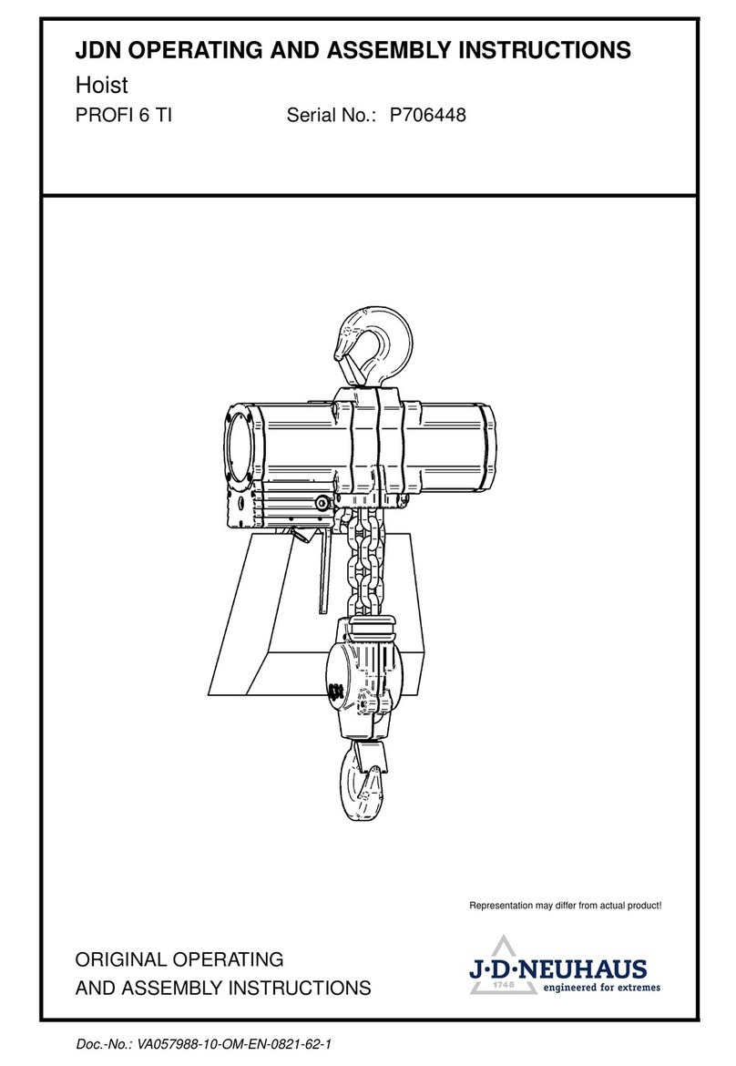
J. D. NEUHAUS
J. D. NEUHAUS PROFI 6 Ti Product guide
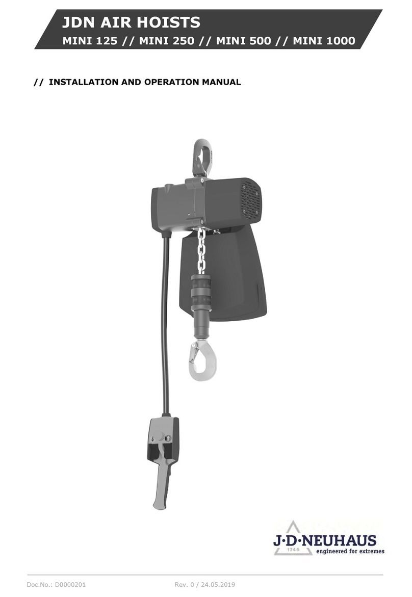
J. D. NEUHAUS
J. D. NEUHAUS JDN mini 125 User manual
J. D. NEUHAUS
J. D. NEUHAUS PROFI 16 Ti Product guide
J. D. NEUHAUS
J. D. NEUHAUS PROFI 2 TI Product guide
J. D. NEUHAUS
J. D. NEUHAUS PROFI 25 TI Product guide
J. D. NEUHAUS
J. D. NEUHAUS Profi 025Ti User manual
J. D. NEUHAUS
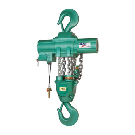
J. D. NEUHAUS PROFI 25TI User manual
