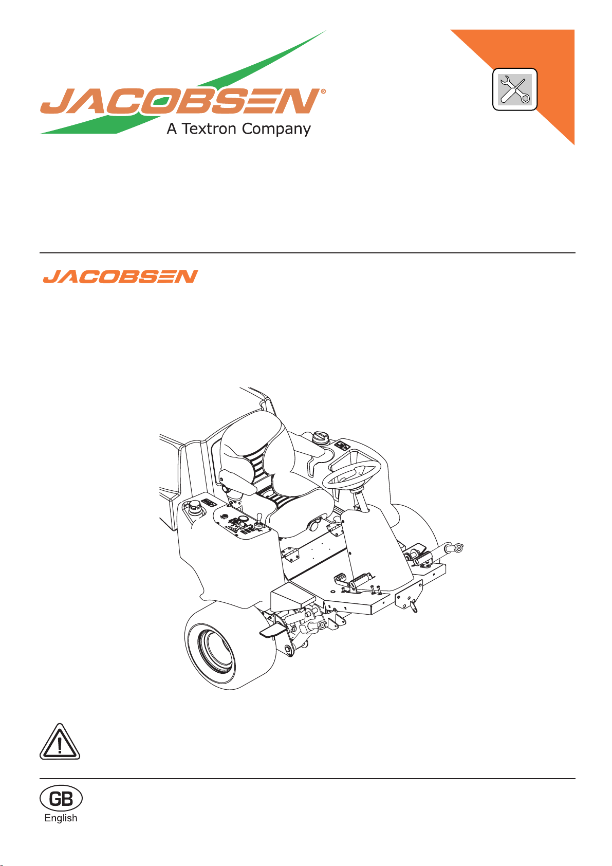
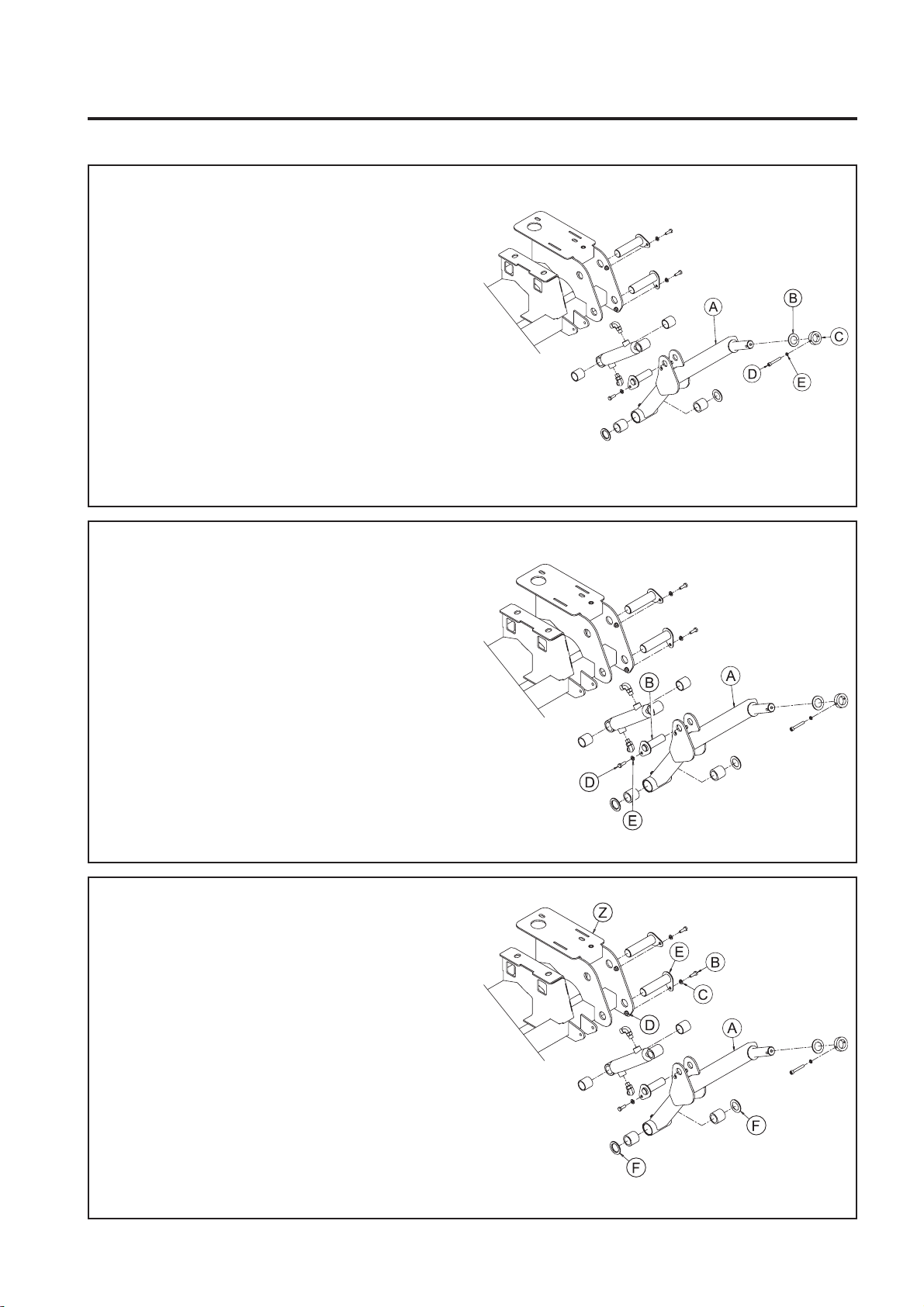
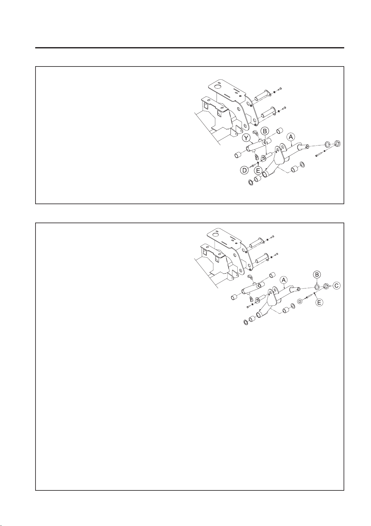
Jacobsen AR3 User manual

WARNING:Ifincorrectlyusedthismachinecancausesevere
injury. Those who use and maintain this machine should be
trained in its proper use, warned of its dangers and should
read the entire manual before attempting to set up, operate,
adjust or service the machine.
FITTING INSTRUCTIONS
RJ 100 08 2005
24772G-GB(rev.1)
AR3 - Narrow Width 1.7m (67in) of Cut Field
Kit LMAC199
For:
Series: FZ - Engine type: Kubota D1105-T
Product codes:AR30002 - 72" Width of Cut

©2005, Ransomes Jacobsen Limited. All Rights Reserved

GB-3
JACOBSEN AR3
NARROW WIDTH OF CUT FIELD KIT
FITTING INSTRUCTIONS
1 CONTENTS
CONTENTS PAGE
2 SAFETYINSTRUCTIONS
2.1 OPERATINGINSTRUCTIONS ..................................................................................... 4
2.2 SAFETYSIGNS .......................................................................................................... 4
2.3 STARTINGTHEENGINE ............................................................................................. 4
2.4 DRIVINGTHEMACHINE ............................................................................................ 4
2.5 TRANSPORTING........................................................................................................ 4
2.6 LEAVINGTHEDRIVINGPOSITION ............................................................................ 4
2.7 SLOPES ..................................................................................................................... 4
2.8 BLOCKEDCUTTINGCYLINDERS .............................................................................. 5
2.9 ADJUSTMENTS,LUBRICATIONANDMAINTENANCE ............................................... 5
3 PREPARATION
3.1 PREPARATION ........................................................................................................... 6
3.2 IMPORTANTNOTE .................................................................................................... 6
4 FRONTLH LIFTARM
4.1 REMOVECUTTINGUNIT FROMLIFTARM ............................................................... 7
4.2 DISCONNECTLIFTRAMFROMLIFTARM ............................................................... 7
4.3 REMOVELIFTARMFROMFRONTAXLE.................................................................. 7
4.4 ASSEMBLENEWLIFTARMTOFRONTAXLE .......................................................... 8
4.5 RECONNECTLIFTRAMTO LIFTARM ..................................................................... 8
4.6 ASSEMBLECUTTINGUNITTOLIFTARM ................................................................ 9
5 CENTRELIFTARM
5.1 REMOVECUTTINGUNIT FROMLIFTARM .............................................................. 10
5.2 DISCONNECTLIFTRAMFROMLIFTARM .............................................................. 10
5.3 REMOVELIFTARM FROMMAINFRAME ................................................................. 11
5.4 ASSEMBLENEW LIFTARM TOMAINFRAME.......................................................... 11
5.5 RECONNECTLIFTRAMTO LIFTARM .................................................................... 12
5.6 ASSEMBLECUTTINGUNITTOLIFTARM ............................................................... 13
5.7 REPOSITIONYOKEBUFFER ...................................................................................... 13
6 PARTSLIST ............................................................................................................. 14
7 NOTES ...................................................................................................................... 18

GB-4
JACOBSEN AR3
NARROW WIDTH OF CUT FIELD KIT
FITTING INSTRUCTIONS
This safety symbol indicates important safety
messages in this manual. When you see this
symbol, be alert to the possibility of injury, carefully
readthemessagethatfollows,andinformother
operators.
2.1 OPERATINGINSTRUCTIONS
• Ensure that the instructions in this book are
readandfullyunderstood.
• Nopersonshould be allowedto operate this
machine unless they are fully acquainted with
all the controls and the safety procedures.
• Neverallowchildrenorpeopleunfamiliarwith
these instructions to use this machine. Local
regulations may restrict the age of the
operator.
2.2 SAFETYSIGNS
• It is essential all safety labels are kept
legible, if they are missing or illegible they
must be replaced. If any part of the machine
is replaced and it originally carried a safety
label, a new label must be affixed to the
replacementpart. New safety labels are
obtainablefromRansomesdealers.
2.3 STARTINGTHEENGINE
• Before starting the engine check that the
brakesareapplied,drivesareinneutral,
guards are in position and intact, and
bystandersare clear of the machine.
• Do not run the engine in a building without
adequateventilation.
2.4 DRIVINGTHEMACHINE
• Beforemovingthe machine,checktoensure
thatall parts are in good working order,
paying particular attention to brakes, tyres,
steering and the security of cutting blades.
• Replace faulty silencers, mow only in daylight
orgoodartificiallight
• AlwaysobservetheHighwayCodebothon
andoff theroads. Keepalert andaware atall
times. Watch out for traffic when crossing or
nearroadways.
• Stoptheblades rotating before crossing
surfacesotherthangrass.
• Rememberthatsomepeoplearedeaforblind
and that children and animals can be
unpredictable.
• Keeptravellingspeedslowenoughforan
emergencystop tobe effectiveand safe at all
times, in any conditions.
• Removeoravoidobstructionsintheareato
be cut, thus reducing the possibility of injury
2 SAFETY INSTRUCTIONS
toyourselfand/orbystanders.
• Whenreversing,take special caretoensure
that the area behind is clear of obstructions
and/orbystanders. DONOTcarrypassengers.
• Keep in mind that the operator or user is
responsibleforaccidentsorhazardsoccurring
tootherpeopleortheir property.
• When the machine is to be parked, stored or
leftunattended, lower the cutting meansunless
the transport locks are being used.
• Whilemowing,always wear substantial
footwearandlongtrousers. Donotoperate the
equipmentwhenbarefootorwearingopen
sandals.
• Checkthegrasscatcherfrequentlyforwearor
deterioration. Afterstrikingaforeignobject
Inspectthelawnmowerfordamageandmake
repairsbeforerestartingandoperatingthe
equipment.
• Ifthemachinestartstovibrate abnormally,
check immediately.
2.5 TRANSPORTING
• Ensure that the cutting units are securely
fastened in the transport position. Do not
transportwith cutting mechanismrotating.
• Drivethemachinewithdueconsiderationof
roadand surfaceconditions, inclines and local
undulations.
2.6 LEAVINGTHEDRIVINGPOSITION
• Parkthemachineonlevelground.
• Beforeleavingthedrivingposition,stopthe
engineandmake sure allmovingpartsare
stationary. Apply brakes and disengage all
drives.Removethestarterkey.
2.7 SLOPES
TAKEEXTRACAREWHENWORKINGON
SLOPES
• Localundulationsand sinkage willchange the
generalslope.Avoidgroundconditionswhich
can cause the machine to slide.
• Keep machine speeds low on slopes and
duringtightturns.
• Remember there is no such thing as a “safe”
slope.
• Travelongrassslopesrequiresparticularcare.
2.8 BLOCKEDCUTTINGCYLINDERS
• Stoptheengine and makesure all moving
partsare stationary.
• Applybrakesanddisengagealldrives.

GB-5
JACOBSEN AR3
NARROW WIDTH OF CUT FIELD KIT
FITTING INSTRUCTIONS
• Release blockages with care. Keep all parts
of the body away from the cutting edge.
Bewareofenergyinthedrivewhichcan
causerotation whenthe blockageis released.
• Keepother people away from the cutting units
as rotation of one cylinder can cause the
others to rotate.
2.9 ADJUSTMENTS,LUBRICATIONAND
MAINTENANCE
• Stoptheengine and makesure all moving
partsare stationary.
• Applybrakesanddisengagealldrives.
• Readalltheappropriateservicinginstructions.
• Use only the replacement parts supplied by
theoriginalmanufacturer.
• When adjusting the cutting cylinders take
carenot to gethands and feettrapped when
rotatingcylinders.
• Makesure thatother peopleare nottouching
any cutting units, as rotation of one cylinder
can cause the others to rotate.
• Toreducethe fire hazard,keeptheengine,
silencerandbatterycompartmentsfreeof
grass,leavesorexcessivegrease.
• Replacewornordamagedpartsforsafety.
• Whenworkingunderneathliftedpartsor
machines,makesureadequatesupportIs
provided.
• Do not dismantle the machine without
releasingorrestrainingforceswhichcan
causeparts to movesuddenly.
DANGER-Indicatesanimminentlyhazardous
situation which, if not avoided, WILL result in death
orserious injury.
WARNING-Indicatesapotentiallyhazardous
situationwhich,ifnot avoided, COULD resultin
deathor serious injury.
CAUTION-Indicatesapotentiallyhazardous
situationwhich, if notavoided, MAY resultin minor
ormoderate injury and property damage. Itmay
also be used to alert against unsafe practices.
2 SAFETY INSTRUCTIONS

GB-6
JACOBSEN AR3
NARROW WIDTH OF CUT FIELD KIT
FITTING INSTRUCTIONS
3 PREPARATION
3.1 PREPARATION
CAUTION:Readthetractor’smanualand
become familiar with the tractor, the controls and
properuseoftheequipment.
Stayalert forpotential hazards and follow all
safetyprecautions. Readall instructions
completelyand makesure you understand them
beforeproceedingwiththeassembly
1. Park the tractor on a flat and level surface, fully
lowertheimplementstotheground,engage
parkingbrake,stoptheengine and remove key
fromignitionswitch.
a. Waitfor all movement tostopbefore
making any adjustments or
modifications.
b. Take this opportunity to thoroughly
inspecttheequipmentandperformother
maintenance.
The“Right” and “Left”,“Front” and “Rear”of the
machineare referenced fromthe operator’s rightand
left when seated in the operator’s seat facing the
directionofforwardtravel.
3.2 IMPORTANTNOTE
1. It is not necessary to break any hydraulic
connections when fitting this Field Kit.
2. Thismodificationwillreducetheprotentialfor
featheringonsideslopes. Howeveritalso
reduces the width of cut from 1.82m (72in) to
1.7m(67in).

GB-7
JACOBSEN AR3
NARROW WIDTH OF CUT FIELD KIT
FITTING INSTRUCTIONS
4.1 REMOVECUTTINGUNITFROMLIFTARM
1. Removecuttingunitdrivemotorfromcutting
unit.
2. RemoveM8 x55 Cap Screw(D),M8
Lockwasher(E)andClampCollar(C)fromLift
Arm (A).
3. Detach Cutting Unit from Lift Arm (A).
4. RemoveThrustWasher(B)fromLiftArm(A)
PivotShaft.
5. Retain items(B), (C),(D) and(E) forfuture use.
4 FRONT LH LIFT ARM
4.2 DISCONNECTLIFTRAMFROMLIFTARM
1. RemoveRam Pin (B) fromLiftArm(A).
2. RetainRamPin (B)and all hardware (D, E and
NylocNut)forfutureuse.
4.3 REMOVELIFTARMFROMFRONTAXLE
1. Remove M8 x 25 Hex Head Screw (B), M8
Plain Washers (C) and M8 Nyloc Nut (D) from
Lift Arm Pivot Pin (E). Retain for future use.
2. RemoveLift ArmPivotPin (E) fromFrontAxle
(Z) / Lift Arm (A). Retain for future use.
3. RemoveLiftArm(A)fromFrontAxle(Z).Retain
NylonWashers(F)for future use.

GB-8
JACOBSEN AR3
NARROW WIDTH OF CUT FIELD KIT
FITTING INSTRUCTIONS
4.4 ASSEMBLENEWLIFT ARMTO FRONT
AXLE
1. Smear bore of new Lift Arm (A) bushes with
ShellDarinaR2grease(orequivalent).
2. CleansurfaceofLiftArmPivotPin(E)(removed
inStep4.3.2)toremoveoldgrease residue.
3. Smear surface of Lift Arm Pivot Pin (E) with
ShellDarinaR2grease(orequivalent).
4. Fit new Lift Arm (A) to Front Axle (Z) fitting
NylonWashers (F) betweenthe FrontAxle (Z)
Plates and the Lift Arm (A) Pivot Housing.
5. Align holes in Lift Arm (A), Nylon Washers (F)
andFrontAxle(Z).
6. Fit Lift Arm Pivot Pin (E) through Front Axle (Z),
Nylon Washers (F) and Lift Arm (A) Pivot
Housing.
Note - Lift Arm Pivot Pin (E) is assembled so
that the flange plate is on the outside of the
machine.
7. Align hole in Lift Arm Pivot Pin (E) Flange Plate
with hole in Front Axle (Z) Plate.
8. Reassemblehardware(B,CandD)(removedin
Step 4.3.1) to Lift Arm Pivot Pin (E) and Front
Axle(Z).
4 FRONT LH LIFT ARM
4.5 RECONNECTLIFTRAMTOLIFTARM
1. Align holes in Lift Ram (Y) and Lift Arm (A).
2. CleansurfaceofRamPin(B)(removedinStep
4.2.1)toremoveoldgreaseresidue.
3. Smearsurface of Ram Pin(B) with Shell Darina
R2grease(orequivalent).
Note - Ram Pin (B) is assembled so that the
flange plate is on the inside of the Lift Arm (A).
4. Align holes in Ram Pin (B) with slot in Lift Arm
(A) Plate.

GB-9
JACOBSEN AR3
NARROW WIDTH OF CUT FIELD KIT
FITTING INSTRUCTIONS
4.5 CONTINUED
5. Reassemblehardware(D,EandNylocNut)
removed in Step 4.2.1 to Ram Pin (B) and Lift
Arm (A).
4.6 ASSEMBLECUTTINGUNITTOLIFTARM
1. Assemble Thrust Washer (B) to Lift Arm (A)
Pivot Shaft so that on assembly it will be
located between the Lift Arm (A) and the Yoke
PivotHousing.
2. Smearsurface of Lift Arm (A) PivotShaft with
ShellDarinaR2grease(orequivalent).
3. Assemble Cutting Unit to Lift Arm (A) Pivot
Shaft.
4. AssembleClampCollar(C)removedinStep
4.1.1 to Lift Arm (A) Pivot Shaft.
5. Align holes in Clamp Collar (C) and Lift Arm (A)
PivotShaft.
6. Reassemblehardware(DandE)removedin
Step 4.1.1
4 FRONT LH LIFT ARM

GB-10
JACOBSEN AR3
NARROW WIDTH OF CUT FIELD KIT
FITTING INSTRUCTIONS
5 CENTRE LIFT ARM
5.1 REMOVECUTTINGUNITFROMLIFTARM
1. RemoveM8 x55 Cap Screw(D),M8
Lockwasher(E)andClampCollar(C)fromLift
Arm (A).
2. Detach Cutting Unit from Lift Arm (A).
3. RemoveThrustWasher(B)fromLiftArm(A)
PivotShaft.
4. Retainitems (B), (C),(D) and(E) forfuture use.
5. RemoveStopBracket(F)fromMainframe.
6. Retainitems (J),(K) and (L)for future use.
7. RemoveRubberBuffer(G)fromStopBracket
(F).
8. Retainitems(G) and (H) forfutureuse.
5.2 DISCONNECTLIFTRAMFROMLIFTARM
1. RemoveRam Pin (B) fromLiftArm(A).
2. RetainRam Pin(B) and allhardware (C, Dand
E)forfuture use.

GB-11
JACOBSEN AR3
NARROW WIDTH OF CUT FIELD KIT
FITTING INSTRUCTIONS
5.3 REMOVELIFTARMFROMMAINFRAME
1. Remove M8 x 25 Hex Head Screw (B), M8
Plain Washer (C) and M8 Nyloc Nut (D) from
Lift Arm Pivot Pin (E). Retain for future use.
2. RemoveLiftArmPivotPin(E)fromMainframe
(Z) / Lift Arm (A). Retain for future use.
3. RemoveLiftArm(A)fromMainframe(Z).Retain
NylonWashers(F)for future use.
5.4 ASSEMBLE NEW LIFT ARM TO
MAINFRAME
1. Smear bore of new Lift Arm (A) bushes with
ShellDarinaR2grease(orequivalent).
2. CleansurfaceofLiftArmPivotPin(E)(removed
inStep5.3.2)toremoveoldgrease residue.
3. Smear Lift Arm Pivot Pin (E) with Shell Darina
R2grease(orequivalent).
4. FitnewLift Arm(A) to Mainframe (Z) fitting
NylonWashers(F)betweentheMainframe
Plates and the Lift Arm (A) Pivot Housing.
5. Align holes in Lift Arm (A), Nylon Washers (F)
andMainframe(Z).
6. FitLiftArm Pivot Pin (E)throughMainframe(Z),
Nylon Washers (F) and Lift Arm (A) Pivot
Housing.
7. Align hole in Lift Arm Pivot Pin (E) Flange Plate
withholeinMainframe(Z)Plate.
5 CENTRE LIFT ARM

GB-12
JACOBSEN AR3
NARROW WIDTH OF CUT FIELD KIT
FITTING INSTRUCTIONS
5 CENTRE LIFT ARM
5.4 CONTINUED
8. Reassemblehardware(B,CandD)(removedin
Step 5.3.1) to Lift Arm Pivot Pin (E) and
Mainframe(Z).
5.5 RECONNECT LIFTRAM TO LIFTARM
1. Align holes in Lift Ram (Y) and Lift Arm (A).
2. CleansurfaceofRamPin (B) removedinStep
5.2.1)toremoveoldgreaseresidue.
3. Smearsurface of Ram Pin(B) with Shell Darina
R2grease(orequivalent)
Note - Ram Pin (B) is assembled so that the
flange plate is on the outside of the Lift Arm
(A).
4. Align holes in Ram Pin (B) with hole in Lift Arm
(A) Plate.
5. Reassemblehardware(C,DandE)removedin
Step 5.2.1 to Ram Pin (B) and Lift Arm (A).

GB-13
JACOBSEN AR3
NARROW WIDTH OF CUT FIELD KIT
FITTING INSTRUCTIONS
5.6 ASSEMBLECUTTINGUNITTOLIFTARM
1. Assemble Thrust Washer (B) to Lift Arm (A)
Pivot Shaft so that on assembly it will be
located between the Lift Arm (A) and the Yoke
PivotHousing.
2. Smearsurface of Lift Arm (A) PivotShaft with
ShellDarinaR2grease(orequivalent).
3. Assemble Cutting Unit to Lift Arm (A) Pivot
Shaft.
4. AssembleClampCollar(C)removedinStep
5.1.1 to Lift Arm (A) Pivot Shaft.
5. Align holes in Clamp Collar (C) and Lift Arm (A)
PivotShaft.
6. Reassemblehardware(DandE)removedin
Step 5.1.1
7. Assemble new Stop Bracket (F) to Mainframe
(Z)withhardware(J,KandL)removedinStep
5.1.6
8. AssembleRubberBuffer(G),removedatStep
5.1.7, to new Stop Bracket (F) using Nut (H).
5 CENTRE LIFT ARM
O
N
M
N
O
P
Q
S
5.7 REPOSITIONYOKEBUFFER
1. RemoveRubber Buffer(N). RetaintheNut(O).
2. Remove Bracket (M) and fixings (P, Q, S) and
retain,ifrequired.
3. Re-attachtheRubberBuffer(N)withNut(O).

GB-14
JACOBSEN AR3
NARROW WIDTH OF CUT FIELD KIT
FITTING INSTRUCTIONS
6 PARTS LIST
LMSE194
LMSE195
4140881

GB-15
JACOBSEN AR3
NARROW WIDTH OF CUT FIELD KIT
FITTING INSTRUCTIONS
ITEM PARTNo DESCRIPTION QTY REMARKS
LMSE194 LiftArm-FrontLH 1
1 002952633 • EndCap-RHS50x50x5 1
2 002993160 • Lubricator-M6x 90Deg 1
3 4130255 • Bush-Devol1-1/4 x 1-5/8 x 1-1/2 2
4 4140813 • Wldmt-Lift Arm LH 1
LMSE195 LiftArm-Centre 1
1 002952633 • EndCap-RHS50x50x5 2
2 002993160 • Lubricator-M6x 90Deg 1
3 4130255 • Bush-Devol1-1/4 x 1-5/8 x 1-1/2 2
4 4140815 • Wldmt-Lift Arm Ctr 1
5 4140881 Bracket-BumperStop 1
6 PARTS LIST

GB-16
JACOBSEN AR3
NARROW WIDTH OF CUT FIELD KIT
FITTING INSTRUCTIONS
6 PARTS LIST
2
1

GB-17
JACOBSEN AR3
NARROW WIDTH OF CUT FIELD KIT
FITTING INSTRUCTIONS
ITEM PARTNo DESCRIPTION QTY REMARKS
1 4142585 Bracket-BumperStop 1 re-used part as instructed
2 450120398 Nut-Hex3/8-16NylocThin 1 re-used part as instructed
6 PARTS LIST

GB-18
JACOBSEN AR3
NARROW WIDTH OF CUT FIELD KIT
FITTING INSTRUCTIONS
7 NOTES


Equipment from Ransomes Jacobsen Limited is built to
exacting standards ensured by ISO 9001 registration at
all our manufacturing locations. A worldwide dealer
network and factory-trained technicians backed by
Ransomes Jacobsen Parts Xpress provide reliable,
high-quality product support.
RansomesJacobsenLimited
WestRoad,RansomesEuropark,Ipswich,England,IP39TT
EnglishCompanyRegistrationNo.1070731
www.ransomesjacobsen.com
World Class Quality, Performance and Support
BOB-CAT BUNTON CUSHMAN JACOBSEN RANSOMES RYAN E-Z-GO
Other manuals for AR3
7
Table of contents
Other Jacobsen Farm Equipment manuals
Popular Farm Equipment manuals by other brands

Hands Free Farm
Hands Free Farm RANGER user guide

Ovlac
Ovlac MINIVID OPERATING INSTRUCIONS AND SPARE PARTS

Hanskamp
Hanskamp PipeFeeder Installation and operating instruction

AKO-Agrartechnik
AKO-Agrartechnik Easy Gate 446517 user guide

VENCE TUDO
VENCE TUDO SA 7300 Operation manual

Tiger
Tiger JD6M MY20 Mounting and operating instructions