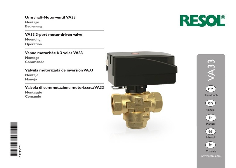
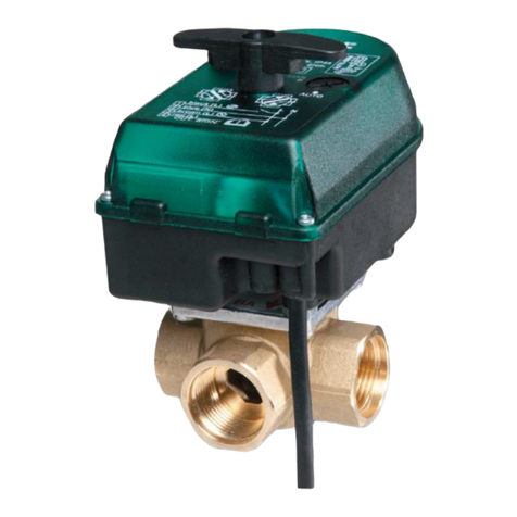
Resol VA23 User manual

*11215610*
11215610
Motorkugelhahn VA23
Montage
Bedienung
VA23 motor-driven 2-port ball valve
Mounting
Operation
Vanne motorisée à 2 voiesVA23
Montage
Commande
Válvula motorizada de dos víasVA23
Montaje
Manejo
Valvola a sfera motorizzataVA23
Montaggio
Comando
www.resol.com
de
Handbuch
VA23
Manual
Manuel
en
fr
es
Manual
it
Manuale

de
2
Angaben zum Gerät
BestimmungsgemäßeVerwendung
Das Ventil und der Stellantrieb sind für Schaltprozesse innerhalb einer Solar- oder
Heizungsanlage unter Berücksichtigung der in dieser Anleitung angegebenen tech-
nischen Daten bestimmt.
Die bestimmungswidrige Verwendung führt zum Ausschluss jeglicher Haftungsan-
sprüche.
JedeVerwendung darüber hinaus gilt als bestimmungswidrig.
Zur bestimmungsgemäßen Verwendung zählt die Einhaltung der Vorgaben dieser
Anleitung.
Hinweis
Starke elektromagnetische Felder können die Funktion des Gerätes
beeinträchtigen.
ÎSicherstellen, dass Gerät und System keinen starken elektromagneti-
schen Strahlungsquellen ausgesetzt sind.
EU-Konformitätserklärung
Das Produkt entspricht den relevanten Richtlinien und ist daher mit
der CE-Kennzeichnung versehen. Die Konformitätserklärung kann beim
Hersteller angefordert werden.
Lieferumfang
Der Lieferumfang dieses Produktes ist auf demVerpackungsaufkleber aufgeführt.
Lagerung undTransport
Das Produkt bei einer Umgebungstemperatur von 0 … 40 °C und in trockenen
Innenräumen lagern.
Das Produkt nur in der Originalverpackung transportieren.
Außerbetriebnahme
1. Das Gerät von der Spannungsversorgung trennen.
2. Das Gerät demontieren.
Vielen Dank für den Kauf dieses RESOL-Gerätes.
Bitte lesen Sie dieseAnleitung sorgfältig durch,um die Leistungsfähigkeit dieses Ge-
rätes optimal nutzen zu können. Bitte bewahren Sie diese Anleitung sorgfältig auf.
Sicherheitshinweise
Bitte beachten Sie diese Sicherheitshinweise genau, um Gefahren und Schäden für
Menschen und Sachwerte auszuschließen.
Gefahr durch elektrischen Schlag:
• Bei Arbeiten muss das Gerät zunächst vom Netz getrennt werden.
• Das Gerät muss jederzeit vom Netz getrennt werden können.
• Das Gerät nicht in Betrieb nehmen, wenn sichtbare Beschädigungen bestehen.
Das Gerät darf nicht von Kindern oder von Personen mit reduzierten körperli-
chen, sinnlichen oder geistigen Fähigkeiten oder ohne Erfahrung und Wissen ver-
wendet werden. Sicherstellen, dass Kinder nicht mit dem Gerät spielen!
BeiVerwendung von glykolhaltigen Flüssigkeiten geeignete Handschuhe, Schutzbril-
le und Atemschutzmaske tragen!
Vor Inbetriebnahme sicherstellen, dass das Gehäuse ordnungsgemäß verschlossen
ist.
Zielgruppe
Diese Anleitung richtet sich ausschließlich an autorisierte Fachkräfte.
Elektroarbeiten dürfen nur von Elektrofachkräften durchgeführt werden.
Die erstmalige Inbetriebnahme hat durch autorisierte Fachkräfte zu erfolgen.
Autorisierte Fachkräfte sind Personen, die über theoretisches Wissen und Erfah-
rungen mit Installation, Inbetriebnahme,Betrieb,Wartung etc. elektrischer/elektro-
nischer Geräte und hydraulischer Systeme sowie über Kenntnis von einschlägigen
Normen und Richtlinien verfügen.
Vorschriften
Beachten Sie bei Arbeiten die jeweiligen, gültigen Normen,Vorschriften und Richt-
linien!

de
3
Entsorgung
• Verpackungsmaterial des Gerätes umweltgerecht entsorgen.
• Am Ende seiner Nutzzeit darf das Produkt nicht zusammen mit dem Siedlungs-
abfall beseitigt werden.Altgeräte müssen durch eine autorisierte Stelle um-
weltgerecht entsorgt werden.Auf Wunsch nehmen wir Ihre bei uns gekauften
Altgeräte zurück und garantieren für eine umweltgerechte Entsorgung.
Symbolerklärung
Warnhinweise sind mit einem Warnsymbol gekennzeichnet!
Signalwörter kennzeichnen die Schwere der Gefahr, die auftritt, wenn sie nicht
vermieden wird.
WARNUNG bedeutet, dass Personenschäden, unter Umständen
auch lebensgefährlicheVerletzungen auftreten können.
ÎEs wird angegeben, wie die Gefahr vermieden
werden kann!
Hinweis
Hinweise sind mit einem Informationssymbol gekennzeichnet.
ÎTextabschnitte, die mit einem Pfeil gekennzeichnet sind, fordern zu einer Hand-
lung auf.
Irrtum und technische Änderungen vorbehalten
© 20210831_11215610_VA23.mon5s.indd

de
4
Technische Daten
Arbeitstemperatur: 2 … 110 °C
Umgebungstemperatur: 1… 55 °C
Max.Arbeitsdruck: 32 bar (3,2 MPa)
Max. Differenzdruck: 6 bar (600 kPa)
Medium: Wasser mit max. 50 % Glykol
Anschlussgewinde: IG Rp ½", ¾", 1", 1¼"
Stellmotor: 230V~, 50 Hz
Stellzeit: 30 s (90°)
Ansteuerung: 2-Punkt-Signal (ein/aus)
Schutzart: IP 44
Material:
Gehäuse: Messing EN 12165 CW617N
Kugel: Messing CW61 7N
Leitung: 3 x 0,75 mm² (Isolierung: PVC)
Durchuss (m3/h)
Druckverlust (kPa)
MotorkugelhahnVA23
Das VA23 ist ein motorisierter 2-Wege-Kugelhahn für die Anwendung in Heiz-,
Kühl- und Brauchwassersystemen.
Inhalt
1 Installation............................................................................................ 5
1.1 Montage ..........................................................................................................................5
1.2 Einbaulage .......................................................................................................................6
1.3 Elektrischer Anschluss .................................................................................................6
2 Manuelle Einstellung............................................................................ 7
3 Ansteuerung 2-Punkt .......................................................................... 7
4 Anwendungsbeispiel............................................................................ 8

de
5
109
45,3
DN
58
57,5
68,5
C
A
DN 15 20 25 32
Anschluss (Rp) ½" ¾" 1" 1 ¼"
Kvs 20 m³/h 45 m³/h 60 m³/h 100 m³/h
A 62 mm 68 mm 81 mm 86 mm
C 104 mm 107 mm 112 mm 117 mm
Gewicht 0,6 kg 0,7 kg 0,9 kg 1,1 kg
1 Installation
WARNUNG! Elektrischer Schlag!
Vor Arbeiten den Stellantrieb von der Spannungsversorgung
trennen!
1.1 Montage
Der Stellantrieb kann in nur einer Stellung auf demVentil befestigt werden.
ÎDen Stellantrieb mit dem Clip auf demVentil befestigen.
321
Die Montage des Ventils ist nach den einschlägigen Regeln der Technik vorzuneh-
men.Dichtmittel- bzw.Hanfreste oder dergleichen,dürfen nicht in denVentilkörper
gelangen. Um eine Blockierung des Ventilkegels zu vermeiden, sind folgende Hin-
weise zu beachten und jegliche Löt- oder Schweißarbeiten in direkter Umgebung
desVentils zu vermeiden.
Hinweis
Um die optimale Betriebssicherheit zu erreichen,wird empfohlen die An-
lage vorher zu spülen und einen entsprechenden Schmutzfänger (0,65
µm) vor jedemVentil (s. Installationsschema) einzubauen.
Flussrichtung-Eingang
1 - Wartungskugelhähne 2 - Schmutzfänger ~ 0,65µm 3 - Motorkugelhahn

de
6
1.2 Einbaulage
Das Ventil kann beliebig (siehe Abb.), jedoch nicht mit dem Antrieb nach unten
montiert werden. Um für Servicearbeiten genügend Arbeitsraum zu erhalten, soll
ein Wand- bzw. Geräteabstand von mindestens 100 mm eingehalten werden.
1.3 Elektrischer Anschluss
ÎDen elektrischen Anschluss gemäß Abbildung vornehmen.
Hinweis
Bei Verlegung der Anschlussleitung darauf achten, dass diese nicht in Wär-
mekontakt mit heißenAnlagenteilen (z.B.Radiator,Rohrleitungen etc.) steht.
L
1
2
VA23
3
N
schwarz
blau
braun

de
7
3 Ansteuerung 2-Punkt
Ader
Schwarz Steuerphase
Liegt der Schaltkontakt L (230V~) vom Regler an,öffnet dasVentil.
Liegt kein Schaltkontakt vom Regler an, wird das Ventil wieder in
Ausgangslage zurückgestellt.
Blau Neutralleiter N (230V~)
Braun Dauerphase L (230V~)
L
1
23
N
schwarz
blau
braun
2 Manuelle Einstellung
Um eine manuelle Einstellung vorzunehmen, den Einstellhebel in die gewünschte
Position drehen.

de
8
4 Anwendungsbeispiel

de
9

Wichtiger Hinweis
Die Texte und Zeichnungen dieser Anleitung entstanden mit größtmöglicher
Sorgfalt und nach bestem Wissen. Da Fehler nie auszuschließen sind, möchten
wir auf folgendes hinweisen:
Grundlage Ihrer Projekte sollten ausschließlich eigene Berechnungen und Planun-
gen an Hand der jeweiligen gültigen Normen und Vorschriften sein.Wir schließen
jegliche Gewähr für die Vollständigkeit aller in dieser Anleitung veröffentlichten
Zeichnungen und Texte aus, sie haben lediglich Beispielcharakter. Werden darin
vermittelte Inhalte benutzt oder angewendet, so geschieht dies ausdrücklich auf
das eigene Risiko des jeweiligen Anwenders. Eine Haftung des Herausgebers für
unsachgemäße, unvollständige oder falsche Angaben und alle daraus eventuell ent-
stehenden Schäden wird grundsätzlich ausgeschlossen.
Anmerkungen
Das Design und die Spezikationen können ohne Vorankündigung geändert werden.
Die Abbildungen können sich geringfügig vom Produktionsmodell unterscheiden.
Impressum
Diese Montage- und Bedienungsanleitung einschließlich aller seiner Teile ist ur-
heberrechtlich geschützt. Eine Verwendung außerhalb des Urheberrechts bedarf
der Zustimmung der Firma RESOL– Elektronische Regelungen GmbH. Dies gilt
insbesondere für Vervielfältigungen / Kopien, Übersetzungen, Mikroverlmungen
und die Einspeicherung in elektronischen Systemen.
© RESOL– Elektronische Regelungen GmbH
RESOL–Elektronische Regelungen GmbH
Heiskampstraße 10
45527 Hattingen/ Germany
Tel.: +49(0)23 24/96 48-0
Fax: +49(0) 2324/ 9648- 755
Internet: www.resol.de
E-Mail: [email protected]
Ihr Fachhändler

VA23 motor-driven 2-port ball valve
Mounting
Operation
www.resol.com
VA23
Manual
en

en
12
Information about the product
Proper usage
The valve and the actuator are designed for switching processes in solar or heating
systems in compliance with the technical data specied in this manual.
Improper use excludes all liability claims.
Any use beyond this is considered improper.
Proper usage also includes compliance with the specications given in this manual.
Note
Strong electromagnetic elds can impair the function of the device.
ÎMake sure the device as well as the system are not exposed to strong
electromagnetic elds.
EU Declaration of conformity
The product complies with the relevant directives and is therefore la-
belled with the CE mark. The Declaration of Conformity is available
upon request, please contact the manufacturer.
Included
The scope of delivery of this product is indicated on the packaging label.
Storage and transport
Store the product at an ambient temperature of 0… 40 °C and in dry interior
rooms only.
Transport the product in its original packaging only.
Decommissioning
1. Disconnect the device from the power supply.
2. Dismount the device.
Thank you for buying this RESOL product.
Please read this manual carefully to get the best performance from this unit. Please
keep this manual safe.
Safety advice
Please pay attention to the following safety advice in order to avoid danger and
damage to people and property.
Danger of electric shock:
• When carrying out works, the device must rst of all be disconnected from the
mains.
• It must be possible to disconnect the device from the mains at any time.
• Do not use the device if it is visibly damaged!
The device must not be used by children or persons with reduced physical,sensory
or mental abilities or without any experience and knowledge. Make sure that chil-
dren do not play with the device!
When using uids containing glycol, wear appropriate gloves, goggles, and breath-
ing mask!
Make sure that the housing is properly closed before commissioning the device.
Target group
These instructions are exclusively addressed to authorised skilled personnel.
Only qualied electricians are allowed to carry out electrical works.
Initial commissioning must be effected by authorised skilled personnel.
Authorised skilled personnel are persons who have theoretical knowledge and ex-
perience with the installation, commissioning, operation, maintenance, etc. of elec-
tric/electronic devices and hydraulic systems and who have knowledge of relevant
standards and directives.
Instructions
Attention must be paid to the valid local standards, regulations and directives!

en
13
Disposal
• Dispose of the packaging in an environmentally sound manner.
• At the end of its working life, the product must not be disposed of as urban
waste. Old appliances must be disposed of by an authorised body in an envi-
ronmentally sound manner. Upon request we will take back your old appliances
bought from us and guarantee an environmentally sound disposal of the devices.
Description of symbols
Warnings are indicated with a warning symbol!
Signal words describe the danger that may occur, when it is not avoided.
WARNING means that injury, possibly life-threatening injury, can
occur.
ÎIt is indicated how to avoid the danger described.
Note
Notes are indicated with an information symbol.
ÎTexts marked with an arrow indicate one single instruction step to be carried
out.
Subject to technical change. Errors excepted.
© 20210831_11215610_VA23.mon5s.indd

en
14
Technical data
Operating temperature: 2… 110 °C
Ambient temperature: 1… 55 °C
Max. operating pressure: 32 bar (3.2 MPa)
Max. differential pressure: 6 bar (600 kPa)
Medium: water with max. 50 % glycol
Connection thread: IT Rp ½", ¾", 1", 1¼"
Actuator: 230V~, 50 Hz
Actuation time: 30 s (90°)
Control: 2-point signal (on/off)
Ingress protection: IP44
Material:
housing: brass EN 12165 CW617N
ball: brass CW61 7N
Cable: 3 x 0.75 mm² (insulation: PVC)
Flow rate (m³/h)
Pressure loss (kPa)
VA23 motor-driven 2-port ball valve
TheVA23 is a motor-driven 2-port ball valve for use in heating, cooling and DHW
systems.
Contents
1 Installation.......................................................................................... 15
1.1 Mounting.......................................................................................................................15
1.2 Installation position ....................................................................................................16
1.3 Electrical connection..................................................................................................16
2 Manual adjustment............................................................................ 17
3 On-Off control ................................................................................... 17
4 Application example ......................................................................... 18

en
15
109
45.3
DN
58
57.5
68.5
C
A
DN 15 20 25 32
Connection (Rp) ½" ¾" 1" 1 ¼"
Kvs 20 m³/h 45 m³/h 60 m³/h 100 m³/h
A 62 mm 68 mm 81 mm 86 mm
C 104 mm 107 mm 112 mm 117 mm
Weight 0.6 kg 0.7 kg 0.9 kg 1.1 kg
1 Installation
WARNING! Electric shock!
Before carrying out works, disconnect the actuator from the
power supply!
1.1 Mounting
The actuator can only be mounted to the valve in one way.
ÎAttach the actuator to the valve by means of the fastening clip.
321
The installation of the valve must be carried out in accordance with the approved
technical regulations. Ensure excess sealing material, tape, etc. does not enter the
valve body. In order to avoid blocking of the valve cone, pay attention to the fol-
lowing advice and avoid all soldering, or welding processes close to the valve.
Note
In order to attain the maximum operating safety and reliability, it is rec-
ommended to ush the system and to insert an appropriate dirt trap
(0.65 µm) in front of each valve (see installation scheme).
Flow direction
1 - Ball valves 2 - Dirt trap ~ 0.65µm 3 - Motor-driven 2-port ball valve

en
16
1.2 Installation position
The valve can be mounted in any position (see gure), but the actuator must not
face downwards. In order to have enough space to carry out maintenance work, a
distance of at least 100 mm should be kept between the valve and walls or other
devices.
1.3 Electrical connection
ÎCarry out the electrical wiring as shown in the gure.
Note
During routing of the cable, the connection cable must not touch hot
system components (e.g. radiator, pipes, etc.)
L
1
2
VA23
3
N
black
blue
brown

en
17
3 On-Off control
Line
Black Control phase
If the controller emits a control signal (L, 230V~), the valve
opens.
If there is no control signal, the valve is put back to the initial
position.
Blue Neutral conductor N (230V~)
Brown Permanent live L (230V~)
L
1
23
N
black
blue
brown
2 Manual adjustment
In order to manually adjust the valve, turn the handle to the desired position.

en
18
4 Application example

en
19

RESOL– Elektronische Regelungen GmbH
Heiskampstraße 10
45527 Hattingen/ Germany
Tel.: +49(0) 23 24/ 9648- 0
Fax: +49(0) 23 24/ 9648- 755
www.resol.com
Distributed by
Important note
The texts and drawings of this manual are correct to the best of our knowledge.As
faults can never be excluded, please note:
Your own calculations and plans, under consideration of the current standards and
directions should only be basis for your projects.We do not offer a guarantee for
the completeness of the drawings and texts of this manual - they only represent
some examples.They can only be used at your own risk. No liability is assumed for
incorrect, incomplete or false information and/ or the resulting damages.
Note
The design and the specications can be changed without notice.
The illustrations may differ from the original product.
Imprint
This mounting- and operation manual including all parts is copyrighted. Another
use outside the copyright requires the approval of the manufacturer.This especially
applies for copies, translations, micro lms and the storage into electronic systems.
© RESOL– Elektronische Regelungen GmbH
Table of contents
Languages:
Other Resol Control Unit manuals

Resol
Resol EM-HP Instruction manual

Resol
Resol DeltaSol MX User manual

Resol
Resol MA10 User manual

Resol
Resol VA32 User manual

Resol
Resol EM User manual

Resol
Resol KM2 User manual

Resol
Resol EM Extension module Instruction manual

Resol
Resol DeltaSol BX L Owner's manual
Resol
Resol RCP12 User manual

Resol
Resol KM2 User manual