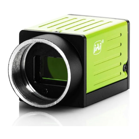
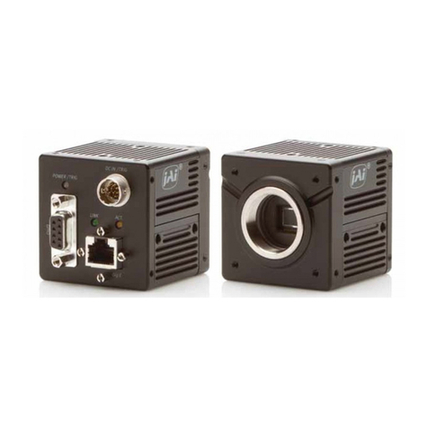
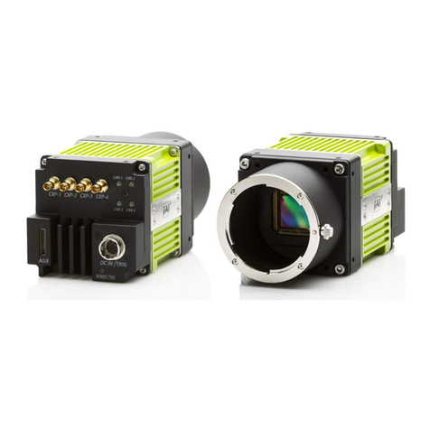
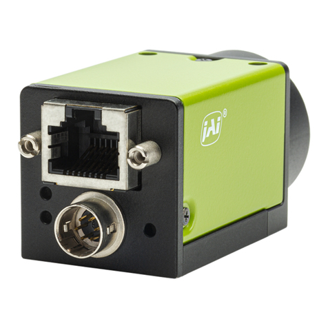
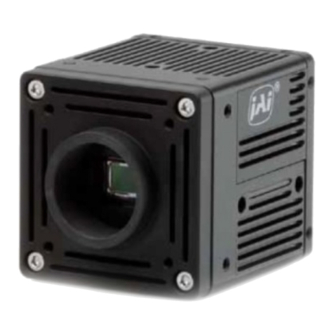
JAI CM-200MCL User manual

User's Manual
CM-200MCL
CB-200MCL
Digital Monochrome / Color
Compact Mini-CL Camera
Document Version: 1.0
Camera Revision: 0

CM-200 MCL / CB-200 MCL
1. 1. General................................................................................................ 3
2. 2. Camera nomenclature .............................................................................. 3
3. 3. Main Features ........................................................................................ 3
4. 4. Locations and Functions ............................................................................ 4
5. Pin Assignment............................................................................................ 5
5.1. 12-pin Multi-connector (DC-IN/Trigger) ........................................................... 5
5.2. Digital Output Connector for Mini-CL (Camera Link)............................................ 5
5.3. Input and output circuits ............................................................................ 6
5.3.1. Iris video output ............................................................................. 6
5.3.2. Trigger input ................................................................................. 6
5.3.3. XEEN output .................................................................................. 6
5.3.4. Camera Link interface ...................................................................... 6
6. Functions and Operations ............................................................................... 7
6.1. Basic functions ........................................................................................ 7
6.1.1. Digital Output Bit Allocation............................................................... 7
6.1.2. Electronic Shutter ........................................................................... 7
6.1.3. Continuous operation or triggered operation ........................................... 8
6.1.4. Iris video output ............................................................................. 8
6.1.5. Rear Panel indicator ........................................................................ 8
6.1.6. Auto-detect LVAL–sync / - a-sync accumulation ....................................... 9
6.1.7. Starting pixel – Bayer color mosaic ....................................................... 9
6.1.8. Vertical Binning.............................................................................10
6.2. Sensor Layout and timing...........................................................................11
6.2.1. CCD Sensor Layout .........................................................................11
6.2.2. Horizontal timing ...........................................................................12
6.2.3. Vertical timing ..............................................................................12
6.2.4. Partial Scanning ............................................................................13
6.2.5. Vertical Binning.............................................................................14
6.3. Operation Modes .....................................................................................15
6.3.1. Continuous operation ......................................................................15
6.3.2. Edge Pre-select Trigger Mode ............................................................15
6.3.3. Pulse Width Control Trigger Mode .......................................................17
6.4. Mode and function matrix. .........................................................................18
7. Configuring the Camera ................................................................................19
7.1. CL-seriel control .....................................................................................19
7.2. Setting functions..................................................................................... 20
7.2.1. Bit allocation BA=0, BA=1 ................................................................20
7.2.2. Partial scan SC=0 through 4.............................................................. 20
7.2.3. Vertical binning VB=0, VB=1............................................................20
7.2.4. Shutter mode SM=0 and SM=1............................................................ 20
7.2.5. Trigger input select TI=0, TI=1. .........................................................20
7.2.6. Trigger polarity. TP=0, TP=1. ............................................................20
7.2.7. Gain level GA= -84 through +336........................................................20
7.2.8. Black level BL=0 through BL=1023. .....................................................20
7.3. Save and Load Functions............................................................................20
7.4. CM-200MCL/CB-200MCL command list............................................................21
8. Camera Control Tool for CM-200MCL / CB-200MCL ................................................23
8.1. Camera Control Tool Interface ....................................................................23
8.1.1. Camera Control Tool Bar ..................................................................23
8.2. The About Window...................................................................................23
8.3. Communication Window ............................................................................24
8.4. Camera Control Window ............................................................................25
- 1 –
CM-200 MCL / CB-200 MCL
8.5. Using the Camera Control Tool ....................................................................25
9. External Appearance and Dimensions ................................................................27
10. Specifications ............................................................................................28
10.1. Spectral response.................................................................................28
10.2. Specification table ............................................................................... 29
11. Appendix ..................................................................................................30
11.1. Precautions ........................................................................................30
11.2. Typical Sensor Characteristics..................................................................30
11.3. References .........................................................................................31
12. User's Record .............................................................................................33
- 2 -

CM-200 MCL / CB-200 MCL
1. General
CM-200 MCL is a monochrome progressive scan CCD camera and CB-200 MCL is the equivalent
Bayer mosaic progressive scan CCD camera. Both have 2.0M pixels resolutions.
These camera are suitable for a wide range of applications within factory automation, an also for
applications outside the factory floor, such as ITS (Intelligent Traffic Solutions), high-end
surveillance and medical.
The latest version of this manual can be downloaded from: www.jai.com
The latest version of Camera Control Tool for CM-200MCL/CB-200MCL can be downloaded from:
www.jai.com
For camera revision history, please contact your local JAI distributor.
2. Camera nomenclature
The standard camera composition consists of the camera main body and C-mount protection cap.
The camera is available in the following versions:
CM-200 MCL
Where Cstands for "Compact" family, Mstands for "Monochrome", 200 represents the resolution "2
million pixel" and MCL stands for "Mini-CL" interface
CB-200 MCL
Where Cstands for "Compact" family, Bstands for "Bayer mosaic color", 200 represents the
resolution "2 million pixel" and MCL stands for "Mini-CL" interface
3. Main Features
•Compact series 1/1.8 inch progressive scan camera
•Monochrome and Bayer mosaic color versions
•1620 (h) x 1236 (v) active pixels
•4.4 µm square pixels
•25 frames / second with full resolution in continuous operation
•24 frames / second with external trigger and full resolution
•Up to 99 frames with partial scan
•49 frames / second with vertical binning ( CM-200 MCL only )
•Shutter speed from 32 µs to 2 second ( 48 frames) using pulse width control
•Programmable exposure from 64 µs to 40 ms
•Pre-Select and Pulse Width control trigger modes
•LVAL –synchronous /-asynchronous operation ( auto –detect )
•Power over CL (PoCL) version available
•Auto iris lens video output allows a wider range of light
•10 bit or 8 bit output
•Set up by Windows NT/Win 2000/ XP via serial communications
- 3 –

CM-200 MCL / CB-200 MCL
4. Locations and Functions
POWER/ TRIG
MINI-CL
① ②
③
④
⑤
⑥
⑥
3-M3depth4
(depth0.16)
C-Mount
Caution seal
FCCseal
(depth0.16)
6-M3depth4
Serial No.
1Lens mount C-mount (Note *1)
2CCD sensor 1/2 inch CCD sensor
326-pin connector Camera Link Interface (Mini-CL)
412-pin connector DC+12V and trigger input (Note *2)
5LED Indication for power and trigger input
6Mounting holes M3 depth 4mm for tripod mount plate
*1) Note: Rear protrusion on C-mount lens must be less than 10.0mm.
*2) Note: Cameras with the PoCL (Power-over-CL) option do not have the 12-pin connector
Fig. 1. Locations
- 4 -

CM-200 MCL / CB-200 MCL
5. Pin Assignment
5.1. 12-pin multi-connector (DC-IN/Trigger)
Type: HR10A-10R-12PB-01(Hirose) male.
Use the part number HR10A-10P-12S for the cable side
Pin no.
Signal
Remarks
1 GND
2 +12 V DC input
3 GND
4 Iris video Only for Continuous mode. TR=0
5 GND
6 NC
7 NC
8 GND
Fig. 2 Hirose 12-pin connecto
r
9 XEEN out
10 Trigger in TI=1. Or Camera Link (TI=0). *1)
11 DC+12V
12 GND
* Note: Factory default is trigger via Camera Link
5.2. Digital Output Connector for Mini-CL (Camera Link)
Type: 26 pin SDR connector (3M or Honda type) Mini-CL connector
Important note:
This camera is also available in a Power over Camera Link (PoCL) version. In this case the 12-
pin Hirose multi connector is not present on the rear panel.
PoCL cameras require special frame grabbers that provide power to the camera via the Camera
Link cable. Please consult www.jai.com (3rd party interfacing section) for information on
available PoCL frame grabbers.
Fig.3. Mini-CL
connector
Pin No
I/O
Name
Note
1,13,14,26 GND DC GND
7(+),20(-) I/O RXD
8(-),21(+) O TXD Serial Com.
10(+),23(-) I Reserve
9(-),22(+) I Trigger CC1 Ext. Trigger in
6(-),19(+) O TxOUT3
4(-),17(+) O TxOUT2
3(-),16(+) O TxOUT1 Camera Link out
2(-),15(+) O TxOUT0
5(-),18(+) O TxClk Clock for CL
- 5 –

CM-200 MCL / CB-200 MCL
5.3. Input and output circuits
In the following schematic diagrams the input and output circuits for video and timing signals are
shown.
5.3.1. Iris video output
GND
75 Video
Output
GND
75 Video
Output
GND
75 Video
Output
This signal can be used for lens iris control in Continuous mode.
The signal is taken from the CCD sensor output before the gain
circuit. The video output is without sync. The signal is 0.7 Vpp
from 75 Ωwithout termination.
NOTE: This function is not available in the PoCL version
Fig. 4. Video output.
5.3.2. Trigger input
GND
+5V
15k
TTL
1k
GND
100n
1k
68k 100k
1n
75Ω
Trig input
pin #10
SW302.1
GND
+5V
15k
TTL
1k
GND
100n
1k
68k 100k
1n
75Ω
Trig input
pin #10
SW302.1
GND
+5V
15k
TTL
1k
GND
100n
1k
68k 100k
1n
75Ω
Trig input
pin #10
SW302.1
Fig. 5. Trigger input.
An external trigger input can be applied to pin 10 of 12-
pin Hirose connector (when the command TI=1 has been
set). The input is AC coupled. To allow long pulses the
input circuit is designed as a flip-flop circuit. The leading
and trailing edges of the trigger pulse activate the
circuit.
The trigger polarity can be changed by TP=1.
Trigger input level 4 V ±2 V.
The trigger can also be supplied through the Camera Link
connector, when the command TI=0 has been set.
NOTE: In the PoCL version trigger can only be applied through the Camera Link connector
GND
+5V
2
2
10k
2k2
75
TTL
100
Pin #9
XEEN
output
GND
+5V
2
2
10k
2k2
75
TTL
100
Pin #9
XEEN
output
5.3.3. XEEN output
XEEN is on pin 9 on 12-pin HR connector. The output
circuit is 75 Ωcomplementary emitter followers. It will
deliver a full 5 volt signal.
Output level ≥4 V from 75Ω. (No termination).
EEN is also found in Camera Link.
NOTE: In the PoCL version EEN is only available in the
Camera Link connector
Fig. 6. XEEN output
5.3.4. Camera Link interface
The digital video is available via Camera Link, with 8 or 10-bit pixel depth, using the CL Base
configuration. The digital output signals follow the Camera Link standard using Channel Link chip
sets.
The data bits from the digital video, FVAL, LVAL, DVAL and EEN are multiplexed into the twisted
pairs, which are a part of the Camera Link. Trigger signals and the serial camera control are feed
directly through its own pairs.
The 26-pin Mini-CL SDR connector pin assignment follows the Camera Link base configuration.
For a detailed description of the Camera Link standard, please refer to the Camera Link standard
specifications found at the AIA web site, www.machinevisiononline.org.
- 6 -

CM-200 MCL / CB-200 MCL
6. Functions and Operations
6.1. Basic functions
The CM-200 MCL / CB-200 MCL cameras are progressive scan camera with 2 Mega pixels
monochrome and Bayer mosaic color CCDs . The interface to the host PC is via digital Mini Camera
Link (Mini-CL). Both models output video as 8 bits or 10 bits. The CB-200 MCL outputs raw Bayer
video requiring host based color interpolation.
An analogue iris video signal can be used for controlling the iris of an auto iris lens when operating
in continuous mode.
The camera has 2/3, 1/2, 1/4 or 1/8 partial scanning and vertical binning ( CM-200MCL only )for
faster frame rates .
There are 2 trigger modes in addition to continuous operation . The Edge Pre-Select and Pulse
Width Control are available with a unique automatic LVAL sync or a-sync selection function.
Below the functions are described in details.
6.1.1. Digital Output Bit Allocation
The 10-bit digital output is set 890 LSB as 100% video level when CCD output is 200mV.
The white clip level is set at 1023 LSB when CCD output is 230mV.
CCD out Analogue Out Digital Out
Black Setup 3.6%, 25mV 32LSB
200mV 700mV 890LSB
230mV 800mV 1023LSB
Digital Out [LSB]
32
70025
Anal og Out [ mV]
890
1023
Bl a c k Level
0
Whi t e Cl i p Level
800
100% Level
Fig.7. Digital Output Bit Allocation
6.1.2. Electronic Shutter
CM-200MCL / CB-200MCL camera allows selecting shutter in two ways ; preset shutter (10 fixed
steps) and programmable exposure ( in 1251 line period, LVAL increment ).
Preset Shutter
- 7 –

CM-200 MCL / CB-200 MCL
The following 10 steps can be selected by command SH=0 through SH=9.
OFF (1/25), 1/60, 1/100, 1/250, 1/500, 1/1000, 1/2000, 1/4000, 1/8000, 1/10000
Programmable Exposure (PE)
The Exposure time can be programmed in 32 µs (1 LVAL period) increments. The range is from 2L
to 1251L.
Minimum shutter speed 2L Maximum shutter speed 1251L
32µs x 2(L) = 64 µs 32µs x 1251 (L) ≈40.032ms
In vertical binning mode
Minimum shutter speed 2L Maximum shutter speed 627L
35.846 µs x 2(L) = 71.692 µs 35.846 µs x 627 (L) ≈22.475 ms
6.1.3. Continuous operation or triggered operation
The camera can operate in continuous mode applications not requiring asynchronous external
trigger. This mode permits the use of a lens with video controlled iris. The camera will operate at
its maximum frame rate, 25 frames / second in this mode.
For applications that require an external trigger, the camera can accept an external trigger input
on pin 10 of the 12-pin Hirose connector or via Camera Link interface. The command “TI” is used
to switch between inputs.
The camera can operate up to 24 frames / second in triggered operation.
6.1.4. Iris video output
The iris video output in pin 4 on the 12-pin Hirose connector is
700 mV for 100% video out in Camera Link. The iris video signal
is taken before the gain circuit. It is without sync. The iris video
signal can be used for auto iris lens drive in continuous mode.
Fig. 8. Iris video output.
6.1.5. Rear Panel indicator
The rear panel mounted LED provides the following information:
Amber: Power connected - initiating
Steady green: Camera is operating in Continuous mode
Flashing green. The camera is receiving external trigger
- 8 -

CM-200 MCL / CB-200 MCL
6.1.6. Auto-detect LVAL–sync / - a-sync accumulation
This function replaces the manual setting found in current JAI cameras. Whether accumulation is
synchronous or a-synchronous in relationship to LVAL depends on the timing of the trigger input.
When a trigger is received while FVAL is high (during readout), the camera works in LVAL
synchronous mode , preventing reset feed through in the video signal. There is a maximum jitter
of one LVAL period from issuing a trigger and accumulation starts.
When trigger is received when FVAL is low, the camera works in LVAL a-synchronous mode ( No
delay ) mode.
This applies to both Pre-Select (PS) trigger and Pulse Width (PW) trigger modes.
Ext. trigge
r
FVAL
(1)
(3)
(1) In this period camera executes trigger at next LVAL (prevents feed-th
r
ough noise)
(2) Avoid trigger at FVAL transition (+/- 1 LVAL period), as the function may randomly switch
between "next LVAL" and "immediate".
(3) In this period camera executes trigger immediately (no delay)
(2)
Fig. 9. Auto-detect LVAL sync /a-sync accumulation
6.1.7. Starting pixel – Bayer color mosaic
CB-200MCL is a color camera based on a CCD
sensor with a Bayer RGB color mosaic. The color
image reconstruction is done in the host PC.
The Color sequence in the video signal
differs from full scanning to partial scanning. The
right hand drawing shows the color sequence at
the image start.
The start line number is shown from FVAL timing.
The start pixel is offset 17 pixels from LVAL when
DVAL rises.
Even lines starts with GBG.
Odd lines starts with RGR
See also chapter 6.3. Partial scan.
F
ig. 10. Bayer color mosaic
FVAL Timing
17
LVAL
DVAL
1
49
71
82
34
11 Full
2/3 Partial
1/2 Partial
1/4 Partial
1/8 Partial
G B
R G
G
R
G B
R G
G
R
G B
R G
G
R
G B
R G
G
R
1
Line # from FVAL
G B
R G
G
R
16 clock
310
1
464
541
207
Actual V Line #
- 9 –

CM-200 MCL / CB-200 MCL
6.1.8. Vertical Binning
This function is only available for CM-200MCL camera.
Binning mode (Command VB) is a function where the signal charge from 2 adjacent (vertical)
pixels are added together and read out as one pixel. Binning results in half vertical resolution and
higher frame rate. By adding 2 pixels together, the sensitivity is doubled. The charge
accumulated in 2 adjacent lines is added together in the horizontal CCD register. This is done by
providing two pulses to the vertical CCD register for each line readout. Vertical binning can not
be used together with the partial scanning.
Normal FUll scanning
2:1 Vertical Binning
H
H
Vertical CCD regiser
Horizontal CCD Register
S/ HReset
Video
Out
Xsg1
Pixel
Fig.11 Vertical Binning
- 10 -

CM-200 MCL / CB-200 MCL
6.2. Sensor Layout and timing
6.2.1. CCD Sensor Layout
The CCD sensor layout with respect to pixels and lines used in the timing and video full frame read
out is shown below.
For Bayer color sequence, refer to chapter 6.1.7.
1 line = 32 μs
1 clock = 15.38 ns
Fig. 12. CCD sensor layout
- 11 –

CM-200 MCL / CB-200 MCL
6.2.2. Horizontal timing
The LVAL period is shown for normal continuous mode.
Hor
i
zonta
l
V
id
eo
T
i
m
i
ng
Full Frame Read out / Partial Read Out
1 LVAL 2080 clk = 32 μs
1 clk = 15.38 ns
LVAL
DATA OUT
DVAL
Valid data
1628 clk
1688 clk
1620 clk
OB
4 clk
48 clk
392 clk
4 clk
OB
12 clk
OB
Fig. 13. Horizontal timing
6.2.3. Vertical timing
The FVAL period for continuous mode full scan is shown.
Vertical Video Timing
Full Frame Read out
Frame rate : 1251L 24.98fps
LVAL
FVAL
DVAL
DATA
EEN
XEEN
1231234 1235 1236
1236L 2L
OB OB
Valid data
3L 10L
CCD Exposure
OB
Fig. 14. Vertical timing for full scan
- 12 -

CM-200 MCL / CB-200 MCL
6.2.4. Partial Scanning
Partial scan allows higher frame rate by reading out a smaller center portion of the image. This is
particularly useful when inspecting objects that do not fill the whole height of the image.
Fast-dump period
Fast-dump period
Normal scan period
Vertical Timing
The below diagram and table provide vertical timing information for the fixed partial scan
settings, 1/2, 1/4, 1/8 and 2/3.
LVAL
FVAL
DVAL
DATA
3L
CCD
Exposure
EEN
XEEN
ABC
Partial Frame Readout
Values for vertical timing in partial scan continuous mode.
B (L)
FVAL Low
(L)
A C Total line frame rate
AREA (L) (L) (L) (L)
Start line End line
618
1/2 3 46 45 712 43.89
309 924
310
1/4 3 68 67 448 69.75
463 773
156
1/8 3 79 78 316 98.89
540 696
824
2/3 3 31 30 888 35.19
206 1030
Remark! The color sequence for CB-200MCL differs in partial scan. Refer to chapter 6.1.7.
Fig. 15. Vertical timing for partial scanning
- 13 –

CM-200 MCL / CB-200 MCL
Horizontal Timing
The horizontal timing is the same as the full scanning.
Hor
i
zonta
l
V
id
eo
T
i
m
i
ng
Full Frame Read out / Partial Read Out
1 LVAL 2080 clk = 32 μs
1 clk = 15.38 ns
LVAL
DATA OUT
DVAL
Valid data
1628 clk
1688 clk
1620 clk
OB
4 clk
48 clk
392 clk
4 clk
OB
12 clk
OB
Fig. 16. Horizontal timing for partial scanning
6.2.5. Vertical Binning
Vertical binning combines charge from two adjacent lines, reducing the vertical resolution to half
and at the same time increasing frame rate and sensitivity. By activating this function, the frame
rate is increased to 44.49 fps.
This function is available only for CM-200MCL.
Important Note
Vertical Binning can not be used together with the Partial Scan.
Horizontal Timing
Horizontal Video Timing
V Binning
1 LVAL 2330 clk = 35.846 μs
LVAL
DATA OUT
DVAL
4 clk 4 clk
OB
Valid data
1 clk = 15.38 ns
48 clk
642 clk
1620 clk
1628 clk
1688 clk
OB
OB
12 clk
Fig.17. Horizontal Timing for Vertical Binning
- 14 -

CM-200 MCL / CB-200 MCL
Vertical timing
V
ertical Video Timing
V Binning
Frame rate : 627L 44.492 fps
LVAL
FVAL
DVAL
DATA
EEN
XEEN
CCD Exposure
Valid data
OB
OB
OB
1+2 3+4
5L3L 618L 1L
1233+1234 1235+1236
Fig.18. Vertical Timing for Vertical Binning
6.3. Operation Modes
This camera can operate in 3 primary modes.
1. TR=0 Continuous Mode. Pre-selected exposure.
2. TR=1 Pre-select Mode. Pre-selected exposure.
3. TR=2 Pulse Width Control Mode.Pulse width controlled exposure.
6.3.1. Continuous operation
For applications not requiring asynchronous external trigger, but should run in continuous
operation, this mode is used.
For timing details, refer to fig. 13 through fig. 18.
To use this mode:
Set function: Trigger mode to “Continuous”. TR=0
Scanning SC=0 through 4
V Binning VB=0, VB=1
Shutter mode pre-set or programmable SM=0 SM=1
Shutter speed SH=0 to 9
Programmable exp. PE=2 to 1252
Other functions and settings
6.3.2. Edge Pre-select Trigger Mode
An external trigger pulse initiates the capture, and the exposure time (accumulation time) is
defined by the SH or PE command.
The resulting video signal will start to be read out after the selected shutter time.
For timing details, refer to fig. 13 through fig. 18 and fig. 19 & 20.
- 15 –

CM-200 MCL / CB-200 MCL
To use this mode:
Set function: Trigger mode to “Edge pre-select”. TR=1
Scanning SC=0 to 4
V Binning VB=0, 1
Shutter mode to normal or programmable SM=0, SM=1
Shutter speed SH=0 to 9
Programmable exp. PE=2 to 1252
Other functions and settings
Input: Ext. trigger. Camera Link or 12 Hirose TI=0, TI=1
Important notes on using this mode
1. The minimum trigger interval >1 LVAL.
2. Depending on the timing of the leading edge of the trigger pulse in relationship to
FVAL, accumulation will be synchronous or a-synchronous in relationship to LVAL.
See chapter 6.1.6. for details.
LVAL Sync mode timing
1L( min.)
Tr i g
LVAL
CCD E x p o s u r e
EEN
XEEN
FVAL
LVAL SYNC Mode Set t i n
g
2L
Exposur e
1L( max)
Tr i gger i nput wht hi n FVAL HI GH Du r a t i o n
Fig. 19. Edge pre-select. LVAL synchronized.
LVAL a-SYNC mode timing
4.86 μs ± 1μs
1L( min.)
CCD exposure
EEN
XEEN
FVAL
2L to 3L
Exposure time
Trig
Trigger input during FVAL LOW period
LVAL a-SYNC mode setting
Fig.20. Edge Pre-select LVAL a-Synchronized
- 16 -

CM-200 MCL / CB-200 MCL
6.3.3. Pulse Width Control Trigger Mode
In this mode the accumulation time is equal the trigger pulse width. Here it is possible to have
long time exposure. The maximum recommended time is <60 frames.
For timing details, refer to fig. 13 through fig. 18 and fig. 21 & 22.
To use this mode:
Set function: Trigger mode to “Pulse width control”. TR=2
Scanning SC=0 to 4
V Binning VB=0, 1
Other functions and settings
Input: Ext. trigger. Camera Link or 12 Hirose TI=0, TI=1
Important notes on using this mode
1. The minimum trigger interval > 1 LVAL
2. Depending on the timing of the leading edge of the trigger pulse in relationship to FVAL,
accumulation will be synchronous or a-synchronous in relationship to LVAL.
See chapter 6.1.6. for the details.
LVAL SYNC Mode timing
Tr i g
CCD E x p o s u r e
Exposur e
EEN
XEEN
FVAL
1L to 2L
2L
1L( Min.)
1L( Max)
LVAL
L VAL SYNC Mode Set t i n
g
Tr i gger i nput wht hi n FVAL HI GH Du r a t i o n
Fig. 21. Pulse width control. LVAL Synchronous.
- 17 –

CM-200 MCL / CB-200 MCL
LVAL a-SYNC mode timing
4. 86 μs ± 1 μs
1L(Min.)
CCD exposure
Trig
2L to 3L
EEN
XEEN
FVAL
Exposure
1L
Trigger input during FVAL LOW period
LVAL a-SYNC mode setting
Fig.22. Pulse Width Control LVAL a-Synchronous
6.4. Mode and function matrix.
The following table shows which functions will work in the different modes for CM-200MCL / CB-
200MCL.
Func. Shutter
Trigger Mode Pre-select
Accumulation Iris
Partial V Binning
Programmabl
e
scan LVAL sync / Video
a-sync out
Continuos TR=0 Yes Yes Yes Yes - Yes
Pre-select TR=1 Yes Yes Yes Yes Yes -
Pulse Width TR=2 - Yes Yes Yes -
Fig. 23. Mode and function matrix.
- 18 -

CM-200 MCL / CB-200 MCL
7. Configuring the Camera
7.1. CL-serial control
All configuration of the CM-200MCL / CB-200MCL camera is done the serial communication in the
Camera Link connector. The camera can be set up from a PC running terminal emulator software,
or using JAI's camera control software.
Below is the description of the ASCII based short command protocol.
Communication setting.
Baud Rate 9600 bps
Data Length 8 bit
Start Bit 1 bit
Stop Bit 1 bit
Parity None
Xon/Xoff Control None
Protocol.
Transmit setting to camera:
NN=[Parameter]<CR><LF> (NN is any kind of command. Capital or small letters.)
The camera answers:
COMPLETE<CR><LF>
To have all communication visible on the emulator screen, start with:
EB=1<CR><LF>
The camera answers:
COMPLETE<CR><LF>
Transmit request command to camera:
NN?<CR><LF> (NN is any kind of command.)
The camera answers:
NN=[Parameter]<CR><LF>
Transmit the following to have the camera actual setting:
ST?<CR><LF>
The camera answers:
A complete list of the current settings
Transmit the following to have a command list:
HP?<CR><LF>
The camera answers:
A list with all commands and possible settings
Invalid parameters send to camera: (99 is an invalid parameter)
SH=99<CR><LF>
The camera answers:
02 Bad Parameters!!<CR><LF>
To see firmware number.
VN?<CR><LF>
To see camera ID. It shows the manufacturing lot number.
ID?<CR><LF>
- 19 –
This manual suits for next models
1
Table of contents
Other JAI Digital Camera manuals

JAI
JAI TM-6740GE User manual

JAI
JAI CV-M9 GE User manual

JAI
JAI SW-4000T-SFP User manual

JAI
JAI RM-2030CL User manual

JAI
JAI GO-5101M-PMCL User manual

JAI
JAI SW-4000M-PMCL User manual

JAI
JAI SW-4000TL-10GE User manual

JAI
JAI GOX-2402M-PGE User manual

JAI
JAI GO-5000M-PMCL User manual

JAI
JAI RM/TM-1327GE Series User manual