JAI LQ-200CL User manual

LQ-200CL
RGB Color & NIR
4CCD Line Scan Camera
Document Version:1.5
LQ-200CL_Ver.1.5_Dec2014
User's Manual

LQ-200CL
2
Notice
The material contained in this manual consists of information that is proprietary to JAI Ltd., Japan
and may only be used by the purchasers of the product. JAI Ltd., Japan makes no warranty for the
use of its product and assumes no responsibility for any errors which may appear or for damages
resulting from the use of the information contained herein. JAI Ltd., Japan reserves the right to
make changes without notice.
Company and product names mentioned in this manual are trademarks or registered trademarks of
their respective owners.
Warranty
For information about the warranty, please contact your factory representative.
Certifications
CE compliance
As defined by the Directive 2004/108/EC of the European Parliament and of the Council, EMC
(Electromagnetic compatibility), JAI Ltd., Japan declares that LQ-200CL complies with the following
provisions applying to its standards.
EN 61000-6-3 (Generic emission standard part 1)
EN 61000-6-2 (Generic immunity standard part 1)
IEC61000-4-2(Electrostatic discharge immunity test)
FCC
This equipment has been tested and found to comply with the limits for a Class B digital device,
pursuant to Part 15 of the FCC Rules. These limits are designed to provide reasonable protection
against harmful interference in a residential installation. This equipment generates, uses and can
radiate radio frequency energy and, if not installed and used in accordance with the instructions,
may cause harmful interference to radio communications. However, there is no guarantee that
interference will not occur in a particular installation. If this equipment does cause harmful
interference to radio or television reception, which can be determined by turning the equipment
off and on, the user is encouraged to try to correct the interference by one or more of the following
measures:
-Reorient or relocate the receiving antenna.
-Increase the separation between the equipment and receiver.
-Connect the equipment into an outlet on a circuit different from that to which the receiver is
connected.
-Consult the dealer or an experienced radio/TV technician for help.
Warning
Changes or modifications to this unit not expressly approved by the party
responsible for FCC compliance could void the user’s authority to operate the
equipment.

LQ-200CL
Supplement
The following statement is related to the regulation on “ Measures for the Administration
of the control of Pollution by Electronic Information Products “ , known as “ China RoHS “.
The table shows contained Hazardous Substances in this camera.
mark shows that the environment-friendly use period of contained Hazardous
Substances is 15 years.
嶷勣廣吭並㍻
嗤蕎嗤墾麗嵎賜圷殆兆各式根楚燕
功象嶄鯖繁酎慌才忽佚連恢匍何〆窮徨佚連恢瞳麟半陣崙砿尖一隈〇
云恢瞳ゞ 嗤蕎
嗤
墾麗嵎賜圷殆兆各式根楚燕 〃泌和
桟隠聞喘豚㍉
窮徨佚連恢瞳嶄根嗤議嗤蕎嗤墾麗嵎賜圷殆壓屎械聞喘議訳周和音氏窟伏翌
亶賜融延、窮徨佚連恢瞳喘薩聞喘乎窮徨佚連恢瞳音氏斤桟廠夛撹冢嶷麟半
賜斤児繁附、夏恢夛撹冢嶷鱒墾議豚㍉。
方忖仝15々葎豚㍉15定。
・・・・・
・・・・・
・・・・・
・・・・・
・・・・・
・・・・・
・・・・・

LQ-200CL
3
-Table of contents –
1. General........................................................................................................ 5
2. Camera nomenclature ...................................................................................... 5
3. Main features................................................................................................. 5
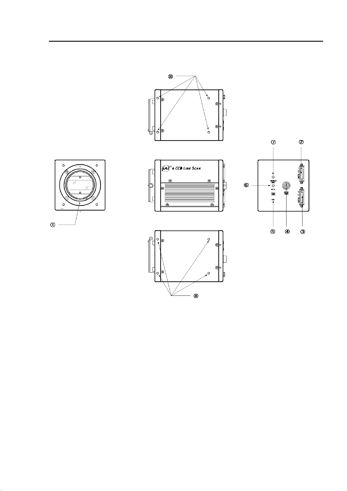
4. Locations and functions .................................................................................... 6
4.1. Locations and functions ............................................................................... 6
4.2. Rear Panel ............................................................................................... 7
5. Connectors and pin assignment ........................................................................... 8
5.1. 12-Pin Connector (Hirose) ............................................................................ 8
5.2. Digital Output / Interface Connectors for CameraLinkTM........................................ 8
5.3. Input and output circuits.............................................................................. 9
5.3.1 Trigger input ........................................................................................ 9
5.3.2 EEN / XEEN output (Exposure ENable).......................................................... 9
5.3.3 Camera Link Interface (Bit allocation) ........................................................ 10
5.3.4 Camera link output port ......................................................................... 11
5.3.5 Bit allocation of the output video.............................................................. 11
6. Functions and Operation .................................................................................. 12
6.1. Basic functions......................................................................................... 12
6.2. Operating mode ....................................................................................... 13
6.2.1 No-Shutter mode with internal trigger ........................................................ 14
6.2.2 No-Shutter mode with external trigger ....................................................... 15
6.2.3 Shutter-Select mode with internal trigger.................................................... 16
6.2.4 Shutter-Select mode with external trigger ................................................... 17
6.2.5 Pulse Width Control (PWC) mode .............................................................. 18
6.3. Scan rate and exposure time range ................................................................ 19
6.3.1 Minimum cycle time of external trigger....................................................... 19
6.3.2 Minimum trigger pulse width.................................................................... 19
6.3.3 Compatibility of trigger modes and functions................................................ 19
6.3.4 Trigger modes and auto white balance modes matrix table............................... 19
7. Functions listed alphabetically by command acronyms.............................................. 20
7.1 Command AHRS –Request Status After One-Push AWB......................................... 20
7.2 Command AL –Automatic Line Rate Reference Level .......................................... 20
7.3 Command AR –Automatic Line Rate Setting ..................................................... 20
7.4 Command ARST –Auto Reset Mode ................................................................ 20
7.5 Command AH - Activate One-Push Auto White Balance (AWB) - Shutter.................... 21
7.6 Command AW –Activate One-Push Auto White Balance (AWB) - Gain....................... 21
7.7 Command BA –Bit Allocation ....................................................................... 21
7.8 Command BI –Binning (horizontal only) .......................................................... 22
7.9 Command BL –Master Black Level ................................................................. 22
7.10 Commands BLR , BLB and BLIR –Black Level Red, Blue and NIR.............................. 22
7.11 Command BLM - Black Level Mode ............................................................... 22
7.12 Command EI –Interlocked R, G, B & NIR Exposure.............................................. 23
7.13 Command GA –Master Gain Level.................................................................. 23
7.14 Commands GAR, GAB and GAIR –Gain Level Red, Blue and NIR. ............................. 23
7.15 Commands GAR2 , GAG2, GAB2 and GAIR2 –Fine Gain (R,G, B and NIR) ................... 24
7.16 Command GM - Gain Mode ...................................................................... 24
7.17 Command LR - Line Rate (Scan Rate) ............................................................. 24
7.18 Command LUTC - LUT Control .................................................................. 24
7.19. Command NR - Noise Reduction ............................................................. 25
7.20 Command PBC –Enable Pixel Black (FPN) Correction .......................................... 25
7.21. Command PBR –Run Pixel Black Correction and Store to User Area ......................... 25
7.22. Command PBS - Request Status After Pixel Black Correction.............................. 26
7.23. Command PER,PEG,PEB and PEIR –Programmable Exposure for R,G,B,and NIR ........... 26
7.24. Command PGC –Enable Flat-Field Correction (pixel gain)..................................... 27
7.25. Command PGR –Pixel Gain Correction and Store in User Area................................ 27
7.26. Command PGS - Request Status After Pixel Gain Correction .............................. 28

LQ-200CL
4
7.27. Command SDC –Select Shading Correction Mode................................................ 29
7.28. Command SDR –Run Shading Correction......................................................... 29
7.29. Command SDS –Request Status After Executing Shading Correction Command .......... 30
7.30. Command TG –Trigger Origin...................................................................... 30
7.31. Command TI –Trigger Input........................................................................ 30
7.32. Command TP –Trigger Polarity.................................................................... 31
7.33. Command TR –Trigger Mode....................................................................... 31
7.34. Command TS –Test Pattern........................................................................ 31
7.35. Command WB –White Balance .................................................................... 32
8. Serial communication and command list ............................................................... 33
8.1. Serial communication................................................................................. 33
8.2. Command list .......................................................................................... 34
9. Camera Control Tool for LQ-200CL ...................................................................... 40
10. External appearance and Dimensions.................................................................. 44
11. Specifications............................................................................................. 45
11.1 Typical data ............................................................................................... 45
11.2 Camera Spectral sensitivity ......................................................................... 47
Appendix............................................................................................................ 48
1. Precautions ............................................................................................... 48
2. Typical Sensor Characteristics......................................................................... 48
3. Caution when mounting a lens on the camera...................................................... 48
4. Caution when mounting the camera.................................................................. 49
5. Exportation ............................................................................................... 49
6. References ................................................................................................ 49
Change history..................................................................................................... 50
User's Record....................................................................................................... 51

LQ-200CL
5
1. General
The LQ-200CL is a 4CCD line scan camera using four 2048 pixel line sensors mounted on a prism, for
the R, G,B and NIR channels. It operates with a 40 MHz pixel clock, resulting in a maximum line rate
of 19,048 lines per second.
The camera outputs digital data in 4 x 8 bits or 4 x 10 bits format via Camera Link. The camera is
configured by software through the serial communication port of the Camera Link interface, or via
RS-232C through a 12-pin Hirose connector.
The camera accepts M52 mount or F-mount lens.
The LQ-200CL is a suitable camera for various applications such as inspection of fruits,
vegetables ,circuits boards or electronic/mechanical parts, as the NIR image can catch scratches or
blemishes on object surfaces which the RGB color image cannot find.
The latest version of the operation manual can be downloaded from www.jai.com .
The latest camera control tool for the LQ-200CL can be downloaded from www.jai.com .
For camera revision history, please contact your local JAI distributor
2. Camera nomenclature
The standard camera composition consists of the camera main body and sensor protection cap.
The camera is available in the following versions:
LQ-200CL
Where L stands for "Line sensor, Q stands for "Quad CCD", 200 represents the resolution "2000 pixels",
and CL stands for "CameraLinkTM" interface.
3. Main features
4CCD line scan camera with 2048 pixel resolution
Dichroic beam splitter prism to separate R,G,B and NIR wavelengths
19,048 lines per second scan rate
40 MHz pixel clock
4 x 8 bits or 4 x 10 bits output through Camera Link interface
Flat-field correction. Two point pixel-by-pixel compensation on each R,G,B and NIR
channels
Master gain control in the range of -3dB to +12dB with a fine gain control
Flat Shading correction and Color Shading Compensation
One-push auto white balance
Binning function to increase sensitivity
Gamma correction using LUT(Look Up Table)
Auto reset function
Noise reduction function
Test pattern generator( color bar, gray, white ) for set-up and trouble shooting
Electronic shutter (for selected modes)
Short ASCII commands set-up via RS 232C or Camera Link
M52 mount or F mount selectable
Setup by Windows XP software
About M52 mount: LQ-200CL employs a new M52 mount as the standard. This mount is
recommended in the lens guide line for machine vision applications which is set by Japan
Industrial Imaging Association in corporation with AIA and EMVA. The title of the guideline is
“JIIA LER 004-2010 Recommended Mechanical Interfaces Applied for Each Image Size
Classification”and issued on March 10th, 2010.

LQ-200CL
6
4. Locations and functions
4.1. Locations and functions
Fig. 1 Location of external features
1 Lens mount M52 mount (*1)Note)
2 Camera Link part 1 base connector (1) (*2)Note)
3 Camera Link part2 medium connector (2) (*2)Note)
4 12-pin Hirose connector DC +12, External trigger and RS-232C
5 DIP switch SW-1 ( refer to chapter 4.2 for the details)
6 Button For one-push auto white balance
7LED indicator Power, trigger input and operation indications
8 Camera mounting holes 8 x M3, depth 5.5mm ± 0.2mm (*3) Note)
*1) Note: Rear protrusion on M52 mount lens must be less than 13mm.
*2) Note: When a CameraLinkTM cable is connected to the camera, please do not excessively tighten
screws by using a driver. The CameraLink receptacle on the camera might be damaged.
For security, the strength to tighten screws is less than 0.291 Newton meter (Nm).
Tightening by hand is sufficient in order to achieve this.
*3) Note: The depth of mounting hole is 5.5mm ± 0.2mm. If the longer screws than 5.7mm are used,
they may damage the circuit board inside.

LQ-200CL
7
4.2. Rear Panel
Fig2. Rear panel
①LED
Green (Steady)
Operating, but not receiving external trigger input
Green (Flashing)
Operating and receiving external trigger input.
Note that the flashing frequency does not correspond to the frequency of the trigger
signal. The flashing does not occur in the No-Shutter internal and Shutter-Select internal
modes.
Orange
Initializing and cannot operate
1) Initializing for approx. 800ms
2) One-push auto white balance is engaged.
②DIP switch
SW-1 function
No
Function
Settings
ON
OFF
1
Serial communication
Hirose 12Pin
Camera link (CC1)
2
Termination of External trigger
75Ω
TTL
Note: Factory default settings for both functions are “OFF”.
Fig.3 DIP switch
D IGITAL I / O - 1
D IG ITA L I / O - 2
POW ER /
TRIG
W . B .
DC IN
/TRIG
S W 1
①
②
OFF ON
Serial
Communication
75 Ω

LQ-200CL
8
5. Connectors and pin assignment
5.1. 12-Pin Connector (Hirose)
Type: HR10A-10R-12PB-01 Hirose (Male)
Use the part number HR10A-10P-12S for the cable side
Pin No.
Signal
Remarks
1
GND
2
+12V DC in
3
GND
4
Reserved
Do not connect
5
GND
6
RxD in
RS-232C
7
TxD out
RS-232C
8
GND
9
XEEN out
10
Trigger in
TI=1, or set TI=0 for input via CL
11
+12V DC in
12
GND
5.2. Digital Output / Interface Connectors for CameraLinkTM
Type: 26P MRD Connector 3M 10226-1A10JL
Fig. 5 Camera Link connector
This camera can be used with all Camera Link products that comply with the AIA Camera Link
standard. Cables, transmission systems and frame grabbers/acquisition boards that do not comply
with the Camera Link standard may work with this camera, but JAI Camera Solutions cannot be
held responsible for loss in performance or damage of equipment, including the camera.
Connector 1 (32Bit, 40 Bit)
Pin No
In/Out
Name
Note
1,14
Shield
GND
2(-),15(+)
O
TxOUT0
Data out
3(-),16(+)
O
TxOUT1
4(-),17(+)
O
TxOUT2
5(-),18(+)
O
TxClk
Clock for CL
6(-),19(+)
O
TxOUT3
Data out
7(+),20(-)
I
SerTC (RxD)
LVDS Serial Control
8(-),21(+)
O
SerTFG (TxD)
9(-),22(+)
I
CC1 (Trigger)
Trigger
10(+),23(-)
I
CC2(Reserved)
11,24
N.C
12,25
N.C
13,26
Shield
GND
Fig. 4 12-pin Hirose connector

LQ-200CL
9
Connector 2 ( Used only for 4 x 10 Bit output)
Pin No
In/Out
Name
Note
1,14
Shield
GND
2(-),15(+)
O
TxOUT0
Data out
3(-),16(+)
O
TxOUT1
4(-),17(+)
O
TxOUT2
5(-),18(+)
O
TxClk
Clock for CL
6(-),19(+)
O
TxOUT3
Data out
7(+),20(-)
N.C
8(-),21(+)
N.C
9(-),22(+)
N.C
10(+),23(-)
N.C
11,24
N.C
12,25
N.C
13,26
Shield
GND
5.3. Input and output circuits
5.3.1 Trigger input
The External Trigger signal can be applied
either through the Camera Link connector or
at pin 10 of the 12-pin Hirose connector. The
command to change this setting is TI (Trigger
Input). TI=0 for Camera Link connector
(factory default) and TI=1 for 12-pin Hirose
connector. The input via the 12-pin Hirose
connector is AC coupled.
To allow long pulses, which may be required
when using the Pulse Width Control (PWC)
trigger mode, the input circuit is designed as
a flip-flop circuit. The leading and trailing
edges of the trigger pulse activate the circuit.
The trigger input polarity can be changed by
the command TP. At the 12-pin Hirose connector the External Trigger input is 4V ± 2V (TTL). It can
be changed to 75 ohm termination by a DIP switch setting (SW 1).
5.3.2 EEN / XEEN output (Exposure ENable)
This output corresponds to the exposure
(accumulation) time of the camera. It works
together with all operation modes. It is,
however, not active when the test pattern
function is enabled.
The EEN signal is available at the Camera
Link connector and at the 12-pin Hirose
connector at the same time.
At the Camera Link connector this signal has
positive logic.
At pin 9 of the 12-pin Hirose connector the
signal has negative logic, and is therefore
named XEEN. The output circuit is a 75 ohm
complementary emitter follower. The
circuit is powered from the 5V supply,
resulting in an output level of more than
4V. It is not terminated.
Fig. 7 XEEN Circuit (12-pin Hirose)
Fig. 6 Trigger input (12-pin Hirose)

LQ-200CL
10
5.3.3 Camera Link Interface (Bit allocation)
The LQ-200CL follows the Camera Link standard in all respects.
Port/Signal
8bitx4 output
10bitx4 output
Connector
Pin Name
Port A0
Out1_D0
Out1_D0
1
Tx0
Port A1
Out1_D1
Out1_D1
1
Tx1
Port A2
Out1_D2
Out1_D2
1
Tx2
Port A3
Out1_D3
Out1_D3
1
Tx3
Port A4
Out1_D4
Out1_D4
1
Tx4
Port A5
Out1_D5
Out1_D5
1
Tx6
Port A6
Out1_D6
Out1_D6
1
Tx27
Port A7
Out1_D7
Out1_D7
1
Tx5
Port B0
Out2_D0
Out1_D8
1
Tx7
Port B1
Out2_D1
Out1_D9
1
Tx8
Port B2
Out2_D2
×
1
Tx9
Port B3
Out2_D3
×
1
Tx12
Port B4
Out2_D4
Out2_D8
1
Tx13
Port B5
Out2_D5
Out2_D9
1
Tx14
Port B6
Out2_D6
×
1
Tx10
Port B7
Out2_D7
×
1
Tx11
Port C0
Out3_D0
Out2_D0
1
Tx15
Port C1
Out3_D1
Out2_D1
1
Tx18
Port C2
Out3_D2
Out2_D2
1
Tx19
Port C3
Out3_D3
Out2_D3
1
Tx20
Port C4
Out3_D4
Out2_D4
1
Tx21
Port C5
Out3_D5
Out2_D5
1
Tx22
Port C6
Out3_D6
Out2_D6
1
Tx16
Port C7
Out3_D7
Out2_D7
1
Tx17
Port D0
Out4_D0
Out4_D0
2
Tx0
Port D1
Out4_D1
Out4_D1
2
Tx1
Port D2
Out4_D2
Out4_D2
2
Tx2
Port D3
Out4_D3
Out4_D3
2
Tx3
Port D4
Out4_D4
Out4_D4
2
Tx4
Port D5
Out4_D5
Out4_D5
2
Tx6
Port D6
Out4_D6
Out4_D6
2
Tx27
Port D7
Out4_D7
Out4_D7
2
Tx5
Port E0
×
Out3_D0
2
Tx7
Port E1
×
Out3_D1
2
Tx8
Port E2
×
Out3_D2
2
Tx9
Port E3
×
Out3_D3
2
Tx12
Port E4
×
Out3_D4
2
Tx13
Port E5
×
Out3_D5
2
Tx14
Port E6
×
Out3_D6
2
Tx10
Port E7
×
Out3_D7
2
Tx11
Port F0
×
Out3_D8
2
Tx15
Port F1
×
Out3_D9
2
Tx18
Port F2
×
×
2
Tx19
Port F3
×
×
2
Tx20
Port F4
×
Out4_D8
2
Tx21
Port F5
×
Out4_D9
2
Tx22
Port F6
×
×
2
Tx16
Port F7
×
×
2
Tx17
LVAL 1
1
Tx24

LQ-200CL
11
FVAL 1
1
Tx25
LVAL 2
2
Tx24
FVAL 2
2
Tx25
DVAL
1
Tx26
EEN
1
Tx23
5.3.4 Camera link output port
LQ-200CL handles R,G,B and NIR channels. The output ports for 8-bit and 10-bit are different.
8 bit output
10 bit output
5.3.5 Bit allocation of the output video
CCD out
Digital
8Bit
(LSB)
Digital
10Bit
(LSB)
Black
8
32
200mV
222
890
230mV
255
1023
Fig.8 Video output
Input signal Camera link output
Camera Link 1 Port a –c
Camera Link 2 Port d –f
RED
GREEN
BLUE
Near IR
Out3
Out4
Out1
Out2
Out5
Out6
Camera Link 1 Port a –c
Camera Link 2 Port d –f
RED
GREEN
BLUE
Near IR
Out3
Out4
Out1
Out2
Out5
Out6
Input signal Camera link output
32
0
CCD_out( mV)
Di gi tal _out ( mV)
Anal og ( mV)
230
1740
2000
200
0
8/32
222/ 890
255/1023
8-bit /10-bit

LQ-200CL
12
6. Functions and Operation
6.1. Basic functions
Fig.9 Signals flow
The LQ-200CL uses four high-performance CCD line scan image sensors mounted on a prism block.
During exposure, the incoming light is converted to electrons (electric charge) in the photodiodes
(active pixels). The transfer gate controls the transfer of charge from photodiodes to the shift
register. Activating the transfer gate terminates the exposure cycle, transfers the charge to the
Horizontal Shift Register (2-phase buried channel CCD shift register) and starts a new exposure
cycle. The line is subsequently read out in a single sequence starting with pixel 1.
The exposure time is normally the same as the cycle time (in No-Shutter mode). By using the
Exposure Control Gate (in Shutter-Select or Pulse Width Control trigger modes) the exposure time
can be individually set to be shorter than the cycle time (the inverse of line rate). This also allows
a fixed exposure time, independent of the line rate. In the LQ-200CL the exposure time can be set
individually for all four channels.
Fig.10 Sensor layout
Dichroic
Prism
Color
Separation
Light
AMP
ADC
Auto black, DSNU, PRNU, Shading,
Fine Gain, Line Matrix, Knee, Noise
reduction, User black
MPX
Digital Binning
MUX / Camera link IF
AMP
ADC
Auto black, DSNU, PRNU, Shading,
Fine Gain, Line Matrix, Knee, Noise
reduction, User black
AMP
ADC
Auto black, DSNU, PRNU, Shading,
Fine Gain, Line Matrix, Knee, Noise
reduction, User black
AMP
ADC
Auto black, DSNU, PRNU, Shading,
Fine Gain, Line Matrix, Knee, Noise
reduction, User black
OUT
PUT
300 400 500 600 700 800 900 1000
300 400 500 600 700 800 900 1000
300 400 500 600 700 800 900 1000
300 400 500 600 700 800 900 1000
Fake_OB10
Fake_OB19
Fake_OB18
Fake_OB17
Fake_OB16
Fake_OB15
Fake_OB14
Fake_OB13
Fake_OB12
Fake_OB11
TP3
TP2
AP2047
AP2046
AP2045
AP2044
・・・・・・・・
I so0
I so2
I so1
2075
I so : I s ol at i on St ages
OB : Opti cal Bl ack Pi xel s
AP : Acti ve Pi xel s
TP : Tr ans i t i on Pi xel s
・・ ・ ・ ・ ・ ・ ・ ・
AP3
AP2
AP1
AP0
1022048210
3
Anti bloomi ng/Exposure Control Gate
OB0
OB1
OB2
OB3
OB4
OB5
OB6
OB7
OB8
OB9
TP0
TP1
Transfer Gate
2-Phase Buried Channel CCD Shift Register
Output

LQ-200CL
13
6.2. Operating mode
The LQ-200CL has three operating modes. They are No-Shutter mode, Shutter-Select mode and PWC
(Pulse Width Control) mode.
The following chapters explain the details of these three modes. The output detail is shown below
and is common with all modes.
Fig.11 Video output timing
Fake_OB19
Fake_OB18
Fake_OB17
Fake_OB16
Fake_OB15
Fake_OB14
Fake_OB13
Fake_OB12
Fake_OB11
Fake_OB10
2100
3
DM23
DM24
DM22
DVAL : Data Val i d
LVAL : Li ne Val i d
1CLK=25ns
DM : Dummy Pi xel s
I so : I sol ati on Stages
OB : Opti cal Bl ack Pi xel s
AP : Acti ve Pi xel s
TP : Transi ti on Pi xel s
有効画素期間
1ライン
102
2048
210322
Data
DVAL
LVAL
TP3
TP2
TP1
TP0
OB9
OB8
OB7
OB6
OB5
OB4
OB3
OB2
OB1
OB0
I so0
I so1
I so2
DM19
DM20
DM21
DM2
DM1
DM0
AP0
AP1
AP2
AP3
・・・・・・・・・ ・ ・ ・ ・ ・ ・ ・ ・
AP2044
AP2045
AP2046
AP2047

LQ-200CL
14
6.2.1 No-Shutter mode with internal trigger
In this mode the camera does not accept an external trigger signal, as the line rate is generated
from an internal clock (user programmable, command LR). The exposure time is directly
proportional to the line rate (Texp = 1/line rate). This mode is used when there is no external
trigger signal available, and the speed of the object is fixed or can be pre-determined.
The line rate can be varied from 1 line period (L) to 1024L in 1 clock (25ns) steps (19 kHz down to
18 Hz). When using this mode, a special function called “One-push auto line rate” is available.
This mode automatically maintains a constant output level by changing the line rate. The line rate
is automatically adjusted in order to maintain sensitivity without reducing the S/N ratio.
To use this mode:
Set function Trigger mode, No-Shutter TR=0
Trigger origin, internal TG=0
Line rate LR=2100 to 2150400
(52.5 µs to 53.8 ms in 25ns increments)
Optional functions when using this mode:
One-push auto line rate AR=0
Auto line rate reference AL=0 to 1023
One-push white balance WB
Fig.12 No-Shutter mode with internal line rate generator
Important Note
Only gain-based one-push white balance function (WB) is available with this mode.
Is o 0
I s o 1
I s o 2
O B 0
O B 1
O B 2
O B 3
OB4
O B 5
O B 6
O B 7
O B 8
O B 9
T P 0
T P 1
A P 0
AP1
A P 2
A P 3
A P 4
A P 5
A P 6
A P 7
A P 8
A P 9
A P 1 0
A P 1 1
A P 1 2
A P 2 0 4 7
AP 2 0 4 6
A P 2 0 4 5
A P 2 0 4 4
A P 2 0 4 3
A P 2 0 4 2
A P 2 0 4 1
A P 2 0 4 0
AP20 3 9
A P 2 0 3 8
AP 2 0 3 7
A P 2 0 3 6
T P 2
T P 3
O B 1 0
O B 1 1
O B 1 2
OB13
O B 1 4
OB15
O B 1 6
OB1 7
O B 1 8
O B 1 9
D M 0
D M 1
D M 2
D M 1 9
DM20
D M 2 1
D M 0
D M 1
D M 2
D M 1 9
D M 2 0
D M 21
φH2
φH1
φPG
φTG
φAB
D M 0
D M 1
D M 2
I s o 0
D M 0
D M 1
D M 2
D M 1 9
D M 2 0
D M 2 1
I s o 1
I s o 2
O B 0
O B 1
O B 2
O B 3
O B 4
O B 5
OB6
O B 7
O B 8
O B 9
T P 0
T P 1
A P 0
A P 1
A P 2
AP3
A P 4
A P 5
A P 6
A P 7
A P 8
A P 9
A P 1 0
A P 1 1
A P 1 2
A P 2 0 4 7
A P 2 0 4 6
A P 2 0 4 5
A P 2 0 4 4
AP204 3
A P 2 0 4 2
AP204 1
A P 2 0 4 0
A P 2 0 3 9
A P 2 0 3 8
A P 2 0 3 7
A P 2 0 3 6
T P 2
T P 3
OB10
O B 1 1
O B 1 2
O B 1 3
O B 1 4
O B 1 5
O B 1 6
O B 1 7
O B 1 8
OB19
Data
LVAL
DVAL
EEN
Line rate 1L to 1024L
Effective Video
2048
Clearer timing diagram
required. No need to show
internal clock signals.

LQ-200CL
15
6.2.2 No-Shutter mode with external trigger
In this mode, the exposure time is directly proportional to the line rate. The line rate is generated
externally by a trigger signal. This mode is used when an external trigger signal available, e.g.
from an encoder, and the scan rate can be controlled by this signal. The camera can accept an
external trigger through the Camera Link connector or though the 12-pin Hirose connector.
To use this mode:
Set function Trigger mode, No-Shutter TR=0
Trigger origin, external TG=1
Trigger input TI=0 or 1
Important note:
When the one-push white balance has been initiated and the rear panel LED shows orange, the
camera must receive continuous external trigger pulses corresponding to the frequency and
duty cycle used in the application.
Only gain-based one-push white balance function (WB) is available with this mode
The minimum trigger interval is 52.6μs.
Fig. 13 No-Shutter mode with external trigger
I so0
I so1
I so2
OB0
OB1
OB2
OB3
OB4
OB5
OB6
OB7
OB8
OB9
TP0
TP1
AP0
AP1
AP2
AP3
AP4
AP5
AP6
AP7
AP8
AP9
AP10
AP11
AP12
AP2047
AP2046
AP2045
AP2044
AP2043
AP2042
AP2041
AP2040
AP2039
AP2038
AP2037
AP2036
TP2
TP3
OB10
OB11
OB12
OB13
OB14
OB15
OB16
OB17
OB18
OB19
DM19
DM20
DM21
DM0
DM1
DM2
φH2
φH1
φPG
φTG
φAB
Data
LVAL
DVAL
EEN
TRI GGER
I so0
I so1
I so2
OB0
OB1
OB2
OB3
OB4
OB5
OB6
OB7
OB8
OB9
TP0
TP1
AP0
AP1
AP2
AP3
AP4
AP5
AP6
AP7
AP8
AP9
AP10
AP11
AP12
AP2047
AP2046
AP2045
AP2044
AP2043
AP2042
AP2041
AP2040
AP2039
AP2038
AP2037
AP2036
TP2
TP3
OB10
OB11
OB12
OB13
OB14
OB15
OB16
OB17
OB18
OB19
DM19
DM20
DM21
20(34)
20
Effective video
2048

LQ-200CL
16
6.2.3 Shutter-Select mode with internal trigger
This mode allows the user to have full control of the line rate and the exposure time individually,
by programming separate timing generators. Subsequently, the camera does not accept an external
trigger signal in this mode.
To use this mode:
Set function Trigger mode, Shutter-Select TR=1
Line rate LR=52.6μs to 53.683ms
Trigger origin, internal TG=0
Individual R, G and B exposure EI=0(individual)
EI=1(tracking with G)
Programmable exposure PER/PEG/PEB/PEIR=2 to 2150400 (in 25ns
steps)
Important note:
If using individual exposure, the EEN signal represents the channel with the longest exposure
time
The longest shutter operation is the same as the set trigger interval.
If one-push auto white balance is used, using the shutter (command AH) or using the gain
(command AW) depends on applications. If the auto white balance switch located on the rear
panel is used, only the gain is effective.
Fig. 14 Shutter-Select mode with internal line rate generator (and individual exposure)
φH2
φH1
Iso0
DM0
DM1
DM2
DM19
DM20
DM21
Iso1
Iso2
OB0
OB1
OB2
OB3
OB4
OB5
OB6
OB7
OB8
OB9
TP0
TP1
AP0
AP1
AP2
AP3
AP4
AP5
AP6
AP7
AP8
AP9
AP10
AP11
AP12
AP2047
AP2046
AP2045
AP2044
AP2043
AP2042
AP2041
AP2040
AP2039
AP2038
AP2037
AP2036
TP2
TP3
Dat a
φPG
φTG
LVAL
DVAL
EEN
φAB_Rch
φAB_Gch
φAB_Bch
T1 (Rch)
T1 (Gch)
T1 (Bch)
DM0
DM1
DM2
DM21
DM20
DM19
Iso0
Iso1
Iso2
OB0
OB1
OB2
OB3
OB4
OB5
OB6
OB7
OB8
OB9
TP0
TP1
AP0
AP1
AP2
AP3
AP4
AP5
AP6
AP7
AP8
AP9
AP10
AP11
AP12
AP2047
AP2046
AP2045
AP2044
AP2043
AP2042
AP2041
AP2040
AP2039
AP2038
AP2037
AP2036
TP2
TP3
Iso0
Iso1
Iso2
OB0
OB1
DM2
DM1
DM21
DM20
DM19
DM0
30ck
30ck
30ck
Minimum 2ck
Effective Video
2048

LQ-200CL
17
6.2.4 Shutter-Select mode with external trigger
This mode allows the user to have full control of the exposure time, by programming a timing
generator, while the line rate is controlled by an external trigger signal. The camera can accept
an external trigger through the Camera Link connector or though the 12-pin Hirose connector.
To use this mode:
Set function Trigger TR=1
Trigger origin, external TG=1
Individual R, G and B exposure EI=0(individual)
EI=1(tracking with G)
Programmable exposure PER/PEG/PEB/PEIR=2 to 2150400 (in 25ns
steps)
Important note:
If using individual exposure, the EEN signal represents the channel with the longest exposure time
The trigger interval is more than 52.6μs.
If one-push auto white balance is used, using the shutter (command AH) or using the gain
(Command AW) depends on applications. If the auto white balance switch located on the rear
panel is used, only the gain is effective.
When the one-push white balance has been initiated and the rear panel LED shows orange, the
camera must receive continuous external trigger pulses corresponding to the frequency and
duty cycle used in the application.
The maximum trigger period is the interval of the input trigger.
Fig. 15 Shutter-Select mode with external trigger (and individual exposure)
φH2
φH1
DM0
DM1
DM2
Dat a
φPG
φTG
LVAL
DVAL
EEN
φAB_Rch
φAB_Gch
φAB_Bch
DM21
DM20
DM19
Iso0
Iso1
Iso2
OB0
OB1
OB2
OB3
OB4
OB5
OB6
OB7
OB8
OB9
TP0
TP1
AP0
AP1
AP2
AP3
AP4
AP5
AP6
AP7
AP8
AP9
AP10
AP11
AP12
AP2047
AP2046
AP2045
AP2044
AP2043
AP2042
AP2041
AP2040
AP2039
AP2038
AP2037
AP2036
TP2
TP3
TRI GGER
T1 (Rch)
T1 (Gch)
T1 (Bch)
30ck以 内
30ck
30ck
30ck
Effectice Video
2048
Clearer timing diagram
required. No need to show
internal clock signals.

LQ-200CL
18
6.2.5 Pulse Width Control (PWC) mode
In this mode, the user has full control of both the line rate and the exposure time of each line via
the External Trigger input.
At the falling edge of the External Trigger signal, the exposure is initiated, and at the rising edge
the exposure is terminated and read out. The camera can accept an external trigger through the
Camera Link connector or though the 12-pin Hirose connector.
To use this mode:
Set function Trigger mode, PWC TR=2
Important Note:
Possible pulse width:
TTL input via 12P 52.6μs
Camera link input 52.6μs
One-push white balance by gain setting only.
The trigger interval is more than (Exposure period + 52.6μs).
When the one-push white balance has been initiated and the rear panel LED shows orange, the
camera must receive continuous external trigger pulses corresponding to the frequency and
duty cycle used in the application.
Fig. 16 Pulse Width Control mode
I s o 0
I s o 1
I s o 2
O B 0
O B 1
O B 2
O B 3
O B 4
O B 5
OB6
O B 7
O B 8
O B 9
T P 0
T P 1
A P 0
AP1
A P 2
AP3
A P 4
A P 5
A P 6
A P 7
A P 8
A P 9
A P 1 0
A P 1 1
A P 1 2
A P 2 0 4 7
AP 2 046
A P 2 0 4 5
A P 2 0 4 4
A P 2 0 4 3
AP 2 042
A P 2 0 4 1
A P 2 0 4 0
A P 2 0 3 9
A P 2 0 3 8
A P 2 0 3 7
A P 2 0 3 6
T P 2
T P 3
D M 1 9
D M 2 0
D M 2 1
D M 0
D M 1
D M 2
φH2
φH1
φPG
φTG
φAB
Data
LVAL
DVAL
EEN
TRIGGER
30ck
30ck以内
10ck以内
Effective Video
2048

LQ-200CL
19
6.3. Scan rate and exposure time range
6.3.1 Minimum cycle time of external trigger
Mode
Minimum trigger cycle
No-Shutter
C1+52.5μs
Shutter-Select
C1+52.5μs
PWC
Exposure + C2
C1 =0.1μs; C2= 52.6μs
6.3.2 Minimum trigger pulse width.
Mode
Via Camera Link
Via Hirose 12-pin
No-Shutter
500ns
5 µs
Shutter-Select
500ns
5 µs
PWC
52.6µs
52.6μs
6.3.3 Compatibility of trigger modes and functions
Mode
Functions
Trigger
Binning
Pixel gain
& black
correction
Shading
correction
One-Push WB
Gain &
black
level ctr.
Trigger
interval
variable
(Accumu.
variable)
Program
exposure
time
Gain
Shutter
No-Shutter
Internal
Yes
Yes
Yes
Yes
No
Yes
Yes(*1)
No
External
Yes
Yes
Yes
Yes
No
Yes
Yes(*1)
No
Shutter-Select
Internal
Yes
Yes
Yes
Yes
Yes
Yes
Yes(*2)
Yes
External
Yes
Yes
Yes
Yes
Yes
Yes
Yes(*2)
Yes
PWC
External
Yes
Yes
Yes
Yes
No
Yes
No
No
*1: The accumulation period is equal to the trigger interval.
*2: The accumulation period is the setting value for accumulation but the longest period is the
trigger interval.
6.3.4 Trigger modes and auto white balance modes matrix table
Trigger
Control
Manual
One push
gain
One push
shutter
No-Shutter
Internal
Only gain
yes
No
External
Only gain
yes
No
Shutter Select
Internal
yes
yes
yes
External
yes
yes
yes
PWC
Internal
Only gain
yes
No
Table of contents
Other JAI Digital Camera manuals

JAI
JAI BM-500 GE User manual

JAI
JAI GO-5000M-PMCL-UV User manual

JAI
JAI RM-2040GE Series User manual

JAI
JAI SW-2001Q-CL User manual

JAI
JAI GO-2400M-PMCL User manual

JAI
JAI EL-2800M-USB User manual

JAI
JAI PULNiX TM-4100GE User manual

JAI
JAI GO-2400M-PMCL-1 User manual

JAI
JAI TM-6740GE User manual

JAI
JAI CV-A20CL User manual
Popular Digital Camera manuals by other brands

Selcom Security
Selcom Security SEL IRCAM Operation manual

Panasonic
Panasonic Lumix DMC-FH2 Basic operating instructions

Panasonic
Panasonic Lumix DMC-TZ30 Basic operating instructions

Yashica
Yashica Lynx-5000 Instruction booklet

Levenhuk
Levenhuk MED 12M Microscope DigitalCamera user manual

Canon
Canon EOS M5 quick guide