JAI SW-4000TL-SFP User manual

User Manual
SW-4000TL-SFP
Thank you for purchasing this product.
Be sure to read this manual before use.
This manual includes important safety precautions and instructions on how to operate the unit. Be sure to read
this manual to ensure proper operation.
The contents of this manual are subject to change without notice for the purpose of improvement.
© 2019 JAI
High Speed CMOS Trilinear Camera
Document Version: 1.2
SW-4000TL-SFP_Ver.1.2_Nov.2020

EEN (Exposure Enable) Function
33
Test Pattern Function
33
Color Space Conversion
34
Counter And Timer Control Function
35
Tilted View Correction and Chromatic Aberration
Correction
37
Spatial Compensation Function
37
Connecting Rotary Encoders
38
Frame Start Trigger
39
Binning Function
40
ROI (Regional Scanning Function)
40
Chunk Data Function
41
Delayed Readout
41
Event Control Function
42
Action Control Function
43
Layout of pixels
44
Noise reduction digital filter funtion
44
Setting List
45
Feature Properties
45
Miscellaneous
56
Troubleshooting
56
Specifications
57
Spectral Response
59
Dimensions
60
Comparison of the Decibel Display and
Multiplier Display
62
User’s Record
63
Index
64
Revision history
65
Notice/Warranty/Certifications
3
Usage Precautions
5
Features
6
Parts Identifications
7
Preparation
11
Preparation Process
11
Step 1:Installing the Software
11
Step 2:Connecting Devices
12
Step 3:Verifying Camera Operation
14
Step 4:Verifying the Connection between
the Camera and PC
14
Step 5:Changing the Camera Settings
17
Step 6:Adjusting the Image Quality
19
Step 7:Saving the Settings
21
Main Functions
22
Valid Input / Output Combinations
22
GPIO(Digital Input/Output Settings)
23
Pixel Format
23
ExposureMode
24
Image Output Timing
24
Pixel Sensitivity Correction
28
Gain Control
29
Lookup Table (LUT)
30
Gamma Function
31
ShadingCorrection
32
Black Level Correction
32
Variable Line Rate
33
Electronic Shutter
33
Contents
SW-4000TL-SFP
—2 —

Notice
The material contained in this manual consists of information that is proprietary to JAI Ltd., Japan and may only
be used by the purchasers of the product. JAI Ltd., Japan makes no warranty for the use of its product and
assumes no responsibility for any errors which may appear or for damages resulting from the use of the
information contained herein. JAI Ltd., Japan reserves the right to make changes without notice.
Company and product names mentioned in this manual are trademarks or registered trademarks of their
respective owners.
Warranty
For information about the warranty, please contact your factory representative.
Certifications
CE compliance
As defined by the Directive 2004/108/EC of the European Parliament and of the Council, EMC (Electromagnetic
compatibility), JAI Ltd., Japan declares that SW-4000TL-SFP complies with the following provisions applying to
its standards.
EN 61000-6-3 (Generic emission standard part 1)
EN 61000-6-2 (Generic immunity standard part 1)
FCC
This equipment has been tested and found to comply with the limits for a Class B digital device, pursuant to Part
15 of the FCC Rules. These limits are designed to provide reasonable protection against harmful interference in
a residential installation. This equipment generates, uses and can radiate radio frequency energy and, if not
installed and used in accordance with the instructions, may cause harmful interference to radio communications.
However, there is no guarantee that interference will not occur in a particular installation. If this equipment
does cause harmful interference to radio or television reception, which can be determined by turning the
equipment off and on, the user is encouraged to try to correct the interference by one or more of the following
measures:
• Reorient or relocate the receiving antenna.
• Increase the separation between the equipment and receiver.
• Connect the equipment into an outlet on a circuit different from that to which the
receiver is connected.
• Consult the dealer or an experienced radio/TV technician for help.
Warning
Changes or modifications to this unit not expressly approved by the party responsible for FCC compliance could
void the user’s authority to operate the equipment.
— 3 —
SW-4000TL-SFP

—4 —
Supplement
The following statement is related to the regulation on “ Measures for the Administration
of the control of Pollution by Electronic Information Products “ , known as “China RoHS “.
The table shows contained Hazardous Substances in this camera.
mark shows that the environment-friendly use period of contained Hazardous
Substances is 15 years.
SW-4000TL-SFP

Usage Precautions
—5 —
SW-4000TL-SFP
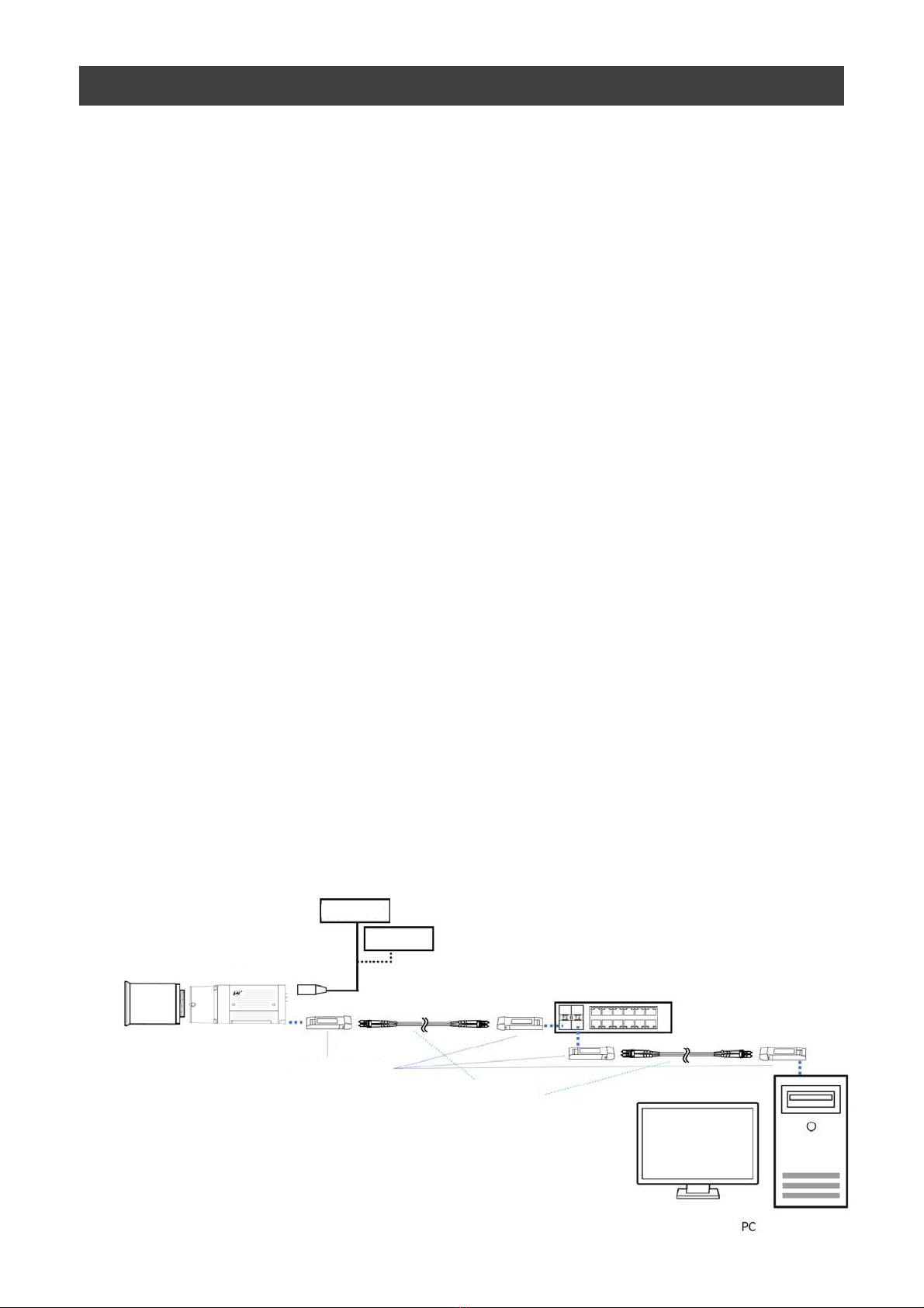
Notes on cable configurations
The presence of lighting equipment and television receivers nearby may result in video noise.
In such cases, change the cable configurations or placement.
Notes on attaching the lens
Avoiding dust particles
When attaching the lens to the camera, stray dust and other particles may adhere to the sensor surface
and rear surface of the lens. Be careful of the following when attaching the lens.
• Work in a clean environment.
• Do not remove the caps from the camera and lens until immediately before you attach the lens.
• To prevent dust from adhering to surfaces, point the camera and lens downward and do not allow the
lens surface to come into contact with your hands or other objects.
•Always use a blower brush to remove any dust that adheres.
Never use your hands or cloth, blow with your mouth, or use other methods to remove dust.
Phenomena specific to CMOS image sensors
The following phenomena are known to occur on cameras equipped with CMOS image sensors.
These do not indicate malfunctions.
• Aliasing
When shooting straight lines, stripes, and similar patterns, vertical aliasing (zigzag distortion) may appear
on the monitor.
• Blooming
When strong light enters the camera, some pixels on the CMOS image sensor may receive much more
light than they are designed to hold, causing the accumulated signal charge to overflow into surrounding
pixels. This “blooming” phenomenon can be seen in the image, but does not affect the operation of the
camera.
• Fixed pattern noise
When shooting dark objects in high-temperature conditions, fixed pattern noise may occur throughout
the entire video monitor screen.
• Defective pixels
Defective pixels (white and black pixels) of the CMOS image sensor are minimized at the factory according
to shipping standards. However, as this phenomenon can be affected by the ambient temperature,
camera settings (e.g., high sensitivity and long exposure), and other factors, be sure to operate within the
camera’s specified operating environment.
Notes on exportation
When exporting this product, please follow the export regulations of your country or region.
Notes on SFP+ module installation
Check the operation manual of the SFP+ module to be used, and attach it or remove it from the camera.
The SFP module can be attached to and removed from the camera only when the camera is turned off.
Many SFP modules and fiber optic cables are Class 1 laser products. Do not look into connectors and cables
when installing or removing. There is a risk of injury to eyes.
Notes on temperature conditions
The guaranteed operating temperature and humidity of this camera are -5℃ to +45℃, 20% to 80%
(non-condensing). Please make sure the following temperature condition is met when operating the unit.
1) The camera's internal temperature sensor detects temperatures of 80 °C or less during operation.
If the above temperature conditions are exceeded, take measures to dissipate heat according to your
installation environment and conditions.
In addition, the operating temperature range of SFP+ modules varies depending on the product.
Please use it after confirming the specifications in the data sheet of the product to be used.
Depending on the operating environment, the surface of the camera
may become very hot during operation.
Do not touch the camera during operation and while it is being cooled.
Also, make sure that the cable surface and other easily deformable
items do not contact the surface of the camera.

Features
SW-4000TL-SFP
—6 —
The SW-4000TL-SFP is a 3 ×4096 pixel trilinear (RGB) CMOS line scan camera.
The Camera is capable of high-speed scanning at up to 66kHz (Line Rate).
8-bit and 10-bit video output is possible via 10GigE.
Features
•Supports 10GBASE-R
Attach an SFP+ module to the camera to enable 10 Gigabit Ethernet
connection via fiber optic cable.
• Trilinear line-scan camera
• Tilted view correction
• Spatial compensation
• Automatic detection of scan direction (when using rotary encoders)
• Support for connection of rotary encoders
• Variety of pre-process functions
• LUT (Lookup Table)
Programmable control over gamma and contrast is possible.
• Gamma correction
Gamma can be set to 1.0, 0.9, 0.8, 0.75, 0.65, 0.6, 0.55, 0.5, or 0.45 (off).
• Shading correction (flat field)
Non-uniformity (i.e., shading) in the amount of light generated by the lens and
lighting equipment can be corrected.
• Variable line rate
By varying the line rate, the scanning speed of the camera can be matched to
the feeding speed of the object, and the accumulation time can be lengthened to
increase sensitivity.
• Miscellaneous
• Timestamp function
• Color space conversion function (HSI, XYZ, sRGB, Adobe RGB) support
Connection example:
Camera
Lens
External Trigger
AC Adaptor
Switching hub
(SFP+ Support)
SFP+ module
Fiber optic cable

Parts Identification
SW-4000TL-SFP
①Lens mount (M42-mount /F-mount)
Mount a M42-mount lens, F-mount lens, etc. here.
❖Before mounting a lens, be sure to refer to “Step 2:Connecting Devices” and confirm
the precautions for attaching a lens and the supported lens types.
—7 —
①
③
⑤
⑥
②
⑥
④

SW-4000TL-SFP
—8 —
②POWER/TRIG LED
Indicates the power and trigger input status.
LED status and camera status
③SFP+ module
The camera supports 10GBASE-R Ethernet standards.
Requirements specification for SFP+ module.
1. Support 10GBASE-R
2. Support Power level 1
Depending on the Ethernet standard to be used, the cable type and the maximum cable
length are limited.
For details, refer to "Step 2 Connecting Devices".
LED Light Status
(Lit amber)
Camera initializing.
SFP+ module not inserted
Not compatible SFP+ module inserted
The Ethernet Link has not been established
(Lit green)
Camera in operation.
(Blinking green)
During operation in trigger mode, trigger signals are
being input
* The blinking interval is not related to the actual input interval of the external
trigger.
POWER/TRIG LED

Pin No.
Input/Output
Signal Description
1GND
2Power In DC In DC 10 V ~ 25 V
3GND
4RESERVED
5In Opto In 1 -
6In Opto In 1 +
7Out TTL Out 4 Line 12
8NC
9Out TTL Out 1 Line 1
10 In TTL In 1 Line 4
11 Power In DC In DC 10 V ~ 25 V
12 GND
Line 5
④DC IN/TRIG connector(12-pin round)
Connect the cable for a power supply (optional) or for DC IN / trigger IN here.
SW-4000TL-SFP
—9 —
TTL signal specification
TTL out signal specification (Typ.)
Output voltage:Low 0.0V
High 5.0V
Input/Output current:+/-32mA
TTL in signal specification (Typ.)
Input voltage:Low 0.0~0.8V
High 2.0~5.5V
Note
Be sure to use a power supply that can support the maximum power consumption of
this camera (12.4 W).
Compatible connectors
Camera side : HR10A-10R-12PB(71)(Hirose Electric or equivalent )
Cable side : HR-10A-10P-12S (plug) (Hirose Electric or equivalent )

Pin No.
Input/Output
Signal Description
1Out TTL_OUT2 Line 8
2Out TTL_OUT3 Line 9
3In TTL_IN2 Line 10
4N.C.
5GND GND
6In TTL_IN3 Line 13
7N.C.
8N.C.
9GND GND
10 GND GND
⑥Camera locking screw holes (M3, 5mm depth)
Use these holes when mounting the camera directly to a wall or other structural
system.
SW-4000TL-SFP
—10 —
⑤AUX connector(10-pin)
User
side
CAMERA
side
User side JAI Camera side
Recommended external input circuit diagram (reference example)
Caution
About Opto In.Check the recommended external input circuit diagram (reference
example) and connect correctly. If you connect Opto In 1 and Opto In 2 in reverse,
camera may be damaged.
Compatible connectors
Camera side:3260-10S3(55)(Hirose Electric or equivalent )
Cable side :3240-10P-C(50)(Hirose Electric or equivalent )

Step 7
Saving the Settings
Save the current setting configurations in user memory.
Step 3
Verifying Camera Operation
Verify whether the camera is turned on and ready for use.
Step 4
Verifying the Connection between the Camera and PC
Verify whether the camera is properly recognized via eBUS SDK for JAI.
Step 5
Configuring Basic Settings for the Camera
Refer to the procedures for basic settings.
Installing the Software (first time only)
Install the software for configuring and controlling the camera (eBUS SDK for JAI) on the computer.
Step 1
Step 2
Connecting Devices
Connect the lens, network cable, AC adapter, computer, and other devices.
Step 6
Adjusting the Image Quality
Refer to the procedures for adjusting the gain, white balance, and black level as examples, and adjust the image
quality.
SW-4000TL-SFP
Preparation
Preparation Process
Step 1: Installing the Software (first time only)
When using the camera for the first time, install the software for configuring and
controlling the camera (eBUS SDK for JAI) on the computer.
❖When you install eBUS SDK for JAI, eBUS SDK for JAI player will also be installed.
Download the eBUS SDK for JAI from the JAI website.
URL https://www.jai.com/jp/support-software/jai-software
Install eBUS SDK for JAI on the computer.
Caution
eBUS SDK for JAI was released in April 2018 and is the latest software for setting and
controlling JAI cameras.
When JAI SDK and eBUS SDK for JAI are installed on the same machine, conflicts can
occur. Therefore, JAI strongly recommends that JAI SDK is uninstalled before installing
eBUS SDK for JAI.
1
2
—11 —

SW-4000TL-SFP
Step 2: Connecting Devices
②Direct connection
Switching hub
or
—12 —
①Lens Camera body
④Fiber optic cable
⑤DC IN/trigger IN
connection cable
⑥AC Adapter (not supplied)
③SFP+ module
AC Adapter
①Lens
・Attach an M42-mount lens or F-mount lens. These with lens mount protrusions of
13mm or less can be attached.
The maximum performance of the camera may not be realized depending on the lens.
Caution
Note
The following formula can be used to estimate the focal length.
focal length = WD/(1 + W/w)
WD: Working distance (distance between lens and object)
W : Width of object
w : Width of sensor 30.72 mm on this camera.
②Direct connection
When mounting the camera directly to another device, for example, use screws that match the
camera locking screw holes on the camera. (M3, 5 mm depth)
For heavy lenses, be sure to support the lens itself. Do not use configurations in which its weight
is supported by the camera.
Caution
Lens mount protrusion
Lens
13 mm or less

SW-4000TL-SFP
—13 —
③SFP+ module
Check the operation manual of the SFP+ module to be used, and attach it or remove it from
the camera.
The SFP+ module can be attached to and removed from the camera only when the camera is
turned off.
Note
・Many SFP+ modules and fiber optic cables are Class 1 laser products. Do not look into
connectors and cables when installing or removing. There is a risk of injury to eyes.
・Do not exceed the operational temperature of this camera and SFP+ module.
④Fiber optic cable
The longest cable length varies depending on the type of 10GBASE-R standard and SFP+
module.
Below, the table shows the relationship diagram between fiber optic cable type and 10GBASE-R
standard.
Correctly select the fiber optic cable type according to the 10GBASE-R standard and SFP+
module to be used.
Maximum Fiber optic cable length
10GBASE-SR : 300m(Fiber optic cable type OM3), 400m(Fiber optic cable type OM4)
10GBASE-LR : 10km(Fiber optic cable type OS2)
10GBASE-ER : 40km(Fiber optic cable type OS2)
⑤DC IN / trigger IN connection cable
⑥AC adapter (power supply) (if necessary)
Connect the AC adapter and the round connector of the connection cable to the DC IN /
trigger IN connector on the camera.

SW-4000TL-SFP
—14 —
Step 3: Verifying Camera Operation
* For details on how to read the LEDs, see “LED status and camera status” in the “Parts
Identification” section.
Step 4: Verifying the Connection between the Camera and PC
Verify whether the camera is properly recognized via Control Tool.
Connecting the Camera to Control Tool
1Startup eBUS Player for JAI
eBUS Player for JAI startup screen appears.
When power is supplied to the camera while the necessary equipment is connected, the
POWER/TRIG LED at the rear of the camera lights amber, and initialization of the camera
starts. When initialization is complete and Ethernet link is established, the POWER/TRIG
LED lights green.
Verify whether power is being supplied to the camera by checking the rear LED.
When properly turned on
Lit Green
eBUS Player for
JAI

SW-4000TL-SFP
—15 —
The connected camera is listed.
Please select one camera.
Push Select / Connect button
2Select the camera you want to configure.

SW-4000TL-SFP
—16 —
3Check that the settings of the selected camera are displayed.
Push the Device control button.
The screen shown below will be displayed. In this window you can adjust various
settings of the camera.
This completes the procedure for verifying whether the camera is properly recognized and
whether control and settings configuration are possible.

Item Setting value / selectable range
Trigger Mode On
Trigger Selector Line Start
Trigger Source Any
Trigger Activation LevelHigh
(high-level duration)
,
LevelLow
(low-level duration)
Exposure Mode TriggerWidth
(control via trigger width)
Item Setting value / selectable range
Trigger Mode On
Trigger Selector Line Start
Trigger Source Any
Trigger Activation
Rising Edge (rising edge of input signal),
Falling Edge (falling edge of input signal)
Exposure Mode Timed (control via exposure time)
Exposure Time Varies depending on settings.
SW-4000TL-SFP
—17 —
Step 5 Configuring Basic Settings for the Camera
1Set [Exposure Mode] to [Timed].
2Specify the exposure time in [Exposure Time].
3Set [Trigger Mode] to [On] and set [Trigger Selector] to [Line Start].
4If necessary, change the [Trigger Source], and [Trigger Activation] settings.
When Controlling the Exposure Time Using Specified Exposure Times
Configure the settings as follows.
■Control via External Triggers
When Controlling the Exposure Time Using the Pulse Width of the Trigger
Input Signal
Configure the settings as follows.
1Set [Trigger Mode] to [On] .
Because this camera automatically performs several correction functions at startup, the first
three lines captured after powering on or resetting the camera will contain incorrect data.
To ensure accuracy, you should not use the first three lines acquired after any power-up or
reset.
Caution

Item Setting value / selectable range
Exposure Mode Off
Item Setting value / selectable range
Trigger Mode Off
Exposure Mode Timed
(control via exposure time)
Exposure Time Varies depending on settings.
Acquisition Line Rate Varies depending on the PixelFormat and Link speed.
SW-4000TL-SFP
—18 —
1Set [Exposure Mode] to [Timed].
2Set [Trigger Mode] to [Off].
3Specify a line period slower than the exposure time in [Acquisition Line Rate].
4Specify the exposure time in [Exposure Time].
When Controlling the Exposure Time Using Specified Exposure Times
Configure the settings as follows.
■Control Without External Triggers
When Not Controlling the Exposure Time
Configure the settings as follows.
The exposure will be performed with an exposure time equal to 1 / line rate.
* The exposure time specified in [Exposure Time] will be disabled.
2Set [Exposure Mode] to [Trigger Width] .
3If necessary, change the [Trigger Source] and [Trigger Activation] settings.

SW-4000TL-SFP
—19 —
Step 6: Adjusting the Image Quality
Display the camera image and adjust the image quality.
Displaying the Image
Display the image captured by the camera.
When you push [Play] button, the camera image appears in right area.
Note
It is recommended to set [GevGVCPPendingAck] in [TransportLayerControl] to True.
When a time-consuming process such as white balance is performed, this camera
returns an Ack response when the process is completed.
In this case, some camera control software may cause a timeout error without waiting
for an Ack response from the camera. When the [GevGVCPPendingAck] setting is
enabled, if a time-consuming process is performed, the camera immediately returns a
Pending Ack response and returns an Ack response when the processing is completed.
The Timeout errors are prevented.

SW-4000TL-SFP
—20 —
6Adjust the white balance.
Adjust the white balance using the automatic adjustment function.
①Place a white sheet of paper or similar object under the same lighting conditions as
the intended subject, and zoom in to capture the white.
White objects near the subject, such as a white cloth or wall, can also be used.
Be sure to prevent the high-intensity spot lights from entering the screen.
The white balance is automatically adjusted.
②Select the [Balance White Auto] tab, and select [Once].
The white balance is automatically adjusted.
3Perform DSNU correction.
◇For details on this setting, “Pixel Sensitivity Correction”.
4Perform PRNU correction.
◇For details on this setting, “Pixel Sensitivity Correction” .
5Adjust the black level.
◇For details on this setting, “Black Level Correction”.
To maximize the performance of the camera, configure its basic function in the following
order.
1Configure the line rate.
◇For details on this setting, “Variable Line Rate”.
2Configure the exposure time.
◇For details on this setting, “Electronic Shutter” .
7Perform spatial correction.
◇For details on this setting, “Spatial Compensation Function” .
Table of contents
Other JAI Digital Camera manuals

JAI
JAI CV-M9 GE User manual

JAI
JAI CV-A33CL User manual

JAI
JAI GO-5000M-PMCL-1 User manual

JAI
JAI GO-5000C-PMCL User manual

JAI
JAI LQ-200CL User manual

JAI
JAI Go-X Series User manual

JAI
JAI SW-4000T-10GE User manual

JAI
JAI SP-12000M-CXP4-XT User manual

JAI
JAI GO-5101M-PMCL-1 User manual

JAI
JAI GOX-6409M-PGE User manual

JAI
JAI EL-2800M-PMCL User manual

JAI
JAI AM-1600GE User manual

JAI
JAI RM/TM-1327GE Series User manual

JAI
JAI CM-030GE User manual

JAI
JAI TM-770 User manual

JAI
JAI EL-2800M-USB User manual

JAI
JAI RM-1405GE User manual

JAI
JAI SW-4000Q-SFP User manual

JAI
JAI GO-5000M-PMCL User manual

JAI
JAI SW-4000M-PMCL User manual