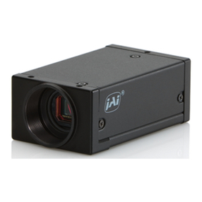
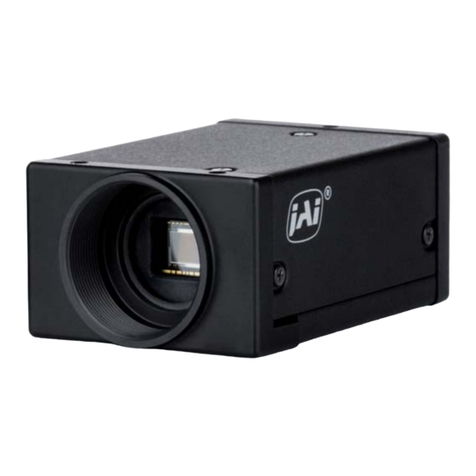
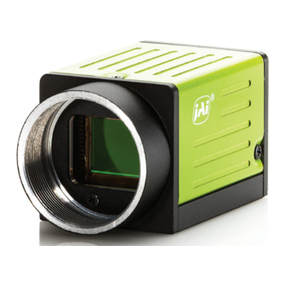
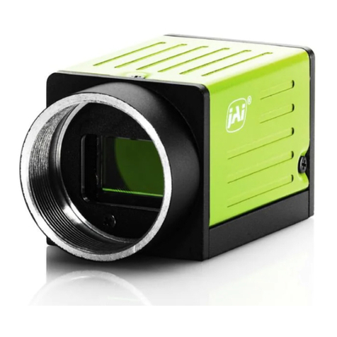
JAI CV-A20CL User manual

Digital monochrome / color
HDTV (1080p) CMOS camera
CV-A20CL
CV-A80CL
Operation Manual
Document Version: 1.0
Camera Revision: 0
Copy right © 2007 JAI All rights reserved

CV-A20CL / CV-A80CL
Plug the connector into the receptacle firmly.
Tighten the two screws securely by hand.
Special Caution
When a Camera Link cable is connected to the camera,
please do not excessively tighten screws by using a screw
driver. The Camera Link receptacle on the camera might
get damaged.
For security, the force used to tighten screws is less than
0.291 Newton Meter (Nm).
Tightening by hand is sufficient in order to achieve this.
3
Ã

CV-A20CL / CV-A80CL
1. General .................................................................................................... 3
2. Standard Composition ................................................................................... 3
3. Main Features............................................................................................. 3
4. Locations and functions................................................................................. 4
5. Pin configuration......................................................................................... 5
5.1. 12-pin multi connector............................................................................... 5
5.2. 26-pin connector (Digital Camera Link Interface) ............................................... 5
5.3. Input and output circuits ............................................................................ 7
5.3.1. Iris video output ................................................................................ 7
5.3.2. Trigger input .................................................................................... 7
5.3.3. Strobe output ................................................................................... 7
6. Functions and Operations............................................................................... 8
6.1. Basic Functions........................................................................................ 8
6.1.1. Formatted Odd and Even Interleaved output .............................................. 8
6.1.2. Strobe-preset Snap-Shot trigger operation ................................................. 8
6.1.3. Window Scan ...................................................................................10
6.1.4. Frame rate for Window Scan Mode .........................................................11
6.1.5. Electronic shutter .............................................................................11
6.2. Image sensor.......................................................................................... 12
6.2.1. Sensor Layout ..................................................................................12
6.2.2. Video output timing via Camera Link ......................................................13
6.3. Inputs and output signals ...........................................................................14
6.3.1. External trigger - Input .......................................................................14
6.3.2. Strobe signal - Output ........................................................................14
6.4. Operation Modes .....................................................................................15
6.4.1. Continuous operation .........................................................................15
6.4.2. Strobe-Preset Snapshot mode ...............................................................15
6.4.3. Widowing Timing Chart ....................................................................... 17
6.4.4. Mode and function compatibility matrix...................................................18
6.4.5. Setting gain and offset ....................................................................... 18
7. Configuring the Camera................................................................................20
7.1. Switch settings .......................................................................................20
7.2. RS-232C control ......................................................................................20
7.3. Save and Load Functions............................................................................21
7.4. CV-A20CL / CV-A80CL Command List .............................................................21
8. Camera Control Tool for CV-A20CL/CV-A80CL .....................................................24
8.1. Camera Control Tool Interface ....................................................................24
8.2. Camera Control Tool Bar ...........................................................................24
8.3. The About Window...................................................................................24
8.4. Communication Window ............................................................................25
8.5. Camera Control Window ............................................................................27
8.6. Using the Camera Control Tool ....................................................................28
9. External Appearance and Dimensions ...............................................................29
10. Specifications............................................................................................30
10.1. Spectral response ....................................................................................30
10.2. Specifications Table .................................................................................31
11. Appendix .................................................................................................32
11.1. Precautions ...........................................................................................32
11.2. Typical Sensor Characteristics .....................................................................32
12. User's Record ............................................................................................ 33
2
CV-A20CL / CV-A80CL
1. General
The CV-A20CL/CV-A80CL uses a newly developed 2 million pixel HDTV (1080p) CMOS Monochrome
and Bayer mosaic color sensor. The sensor has a 2/3 inch format and 16:9 aspect ratio. Total
number of pixels is 2,112 (H) x 1,188(V).
The CV-A20CL/CV-A80CL operates at 60 frames per second with full resolution and at higher frame
rate by using the window-scanning mode.
The CV-A20CL/CV-A80CL has Camera Link standard interface and outputs 8-bit or 10-bit video.
The latest version of this manual can be downloaded from: www.jai.com
The latest version of Camera Control Tool for CV-A20CL/CV-A80CL can also be downloaded from:
www.jai.com
For camera revision history, please contact your local JAI distributor.
2. Standard Composition
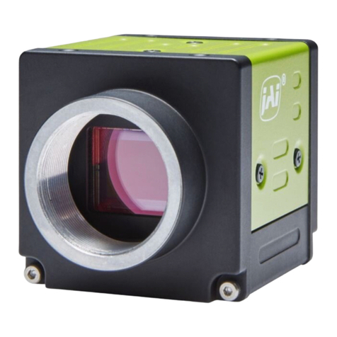
The standard camera composition consists of the camera main body and C-mount protection cap.
The camera is available in the following versions:
CV-A20 CL 2 million pixel HDTV format monochrome CMOS camera
CV-A80 CL 2 million pixel HDTV format Bayer mosaic color CMOS camera
3. Main Features
•Compact 2/3” progressive scan CMOS camera
•Monochrome and Bayer mosaic color versions
•HDTV format with 1920 (h) x 1080 (v) pixels
•5.0 μm square pixels
•60 frames/second with full resolution
•Rolling shutter with snap-shot trigger
•High sensitivity
•Low power consumption
•Shutter speed from 1/60 to 1/20,000 sec. in continuous mode
•Windowing mode for higher frame rate
•10 or 8-bit output
•Setup by Windows NT/2000/XP via serial communication
3

CV-A20CL / CV-A80CL
4. Locations and functions
C- Mount
HI ROSE 12pi n Connect or
Ca mer a Li nk Connect or
①
②
③
④⑤
⑥
⑥
Power/TRIG
1. Camera Link Connector
2. 12-pin Hirose Connector for DC12V, Trigger and RS232C
3. LED indicator
4. C mount *
5. CMOS sensor
6. Mounting holes 10 x M3, depth 4mm
*) Note: Rear protraction on the C-mount lens must be less than 10mm.
Fig.1. Locations
4

CV-A20CL / CV-A80CL
5. Pin configuration
5.1. 12-pin multi connector
Type: HR10A-10R-12PB
Use the part number HR10A-10P-12S for the cable side
5.2. 26-pin connector (Digital Camera Link Interface)
Type: 26P MRD Connector 3M 10226-1A10PL
CV-A20
Connector
Pin No.
Frame Grabber
Connector Pin
No. I/O Name Note
1,13,14,26 1,13,14,26 -- GND DC GND
7(+),20(-) 20(+),7(-) I RXD
21(+),8(-) 6(+),19(-) O TXD RS232C
10(+),23(-) 17(+),4(-) (I) Reserved CC2
22(+),9(-) 5(+),18(-) I Trigger
CC1 Ext. Trigger
15(+),2(-) 12(+),25(-) O Txout0
16(+),3(-) 11(+),24(-) O Txout1
17(+),4(-) 10(+),23(-) O Txout2
19(+),6(-) 8(+),21(-) O Txout3
Camera Link out
18(+),5(-) 9(+),22(-) O TxClk Clock for CL
Pin I/O Name Note
1 -- GND
2 -- +12V Power
3 -- GND
4 O IRIS VIDEO Video signal for Auto Iris Lens
5 -- GND
6 I RXD
7 O TXD
RS-232 C
(default setting is CL serial communication)
8 -- GND
9 O Strobe out Exposure Enable (Active low)
10 I Trigger External Trigger Input
11 -- NC
12 -- GND
Fig. 2 Hirose 12-pin
connector
Fig.3. 26-pin connecto
r
5

CV-A20CL / CV-A80CL
Camera Signals
8 bit 10 bit
Camera Camera Link Cable
Camera Link
DA0
DA9
DA8
DA7
DA6
DA5
DA4
DA3
DA2
DA1
DA0
DA7
DA6
DA5
DA4
DA3
DA2
DA1
DB7
DB4
DB6
DB5
DB3
NC
NC
NC
NC
NC
NC
NC
NC
DB7
DB6
DB2
DB1
DB0
NC
NC
DB9
DB8
NC
NC
DB5
DB4
DB3
DB2
DB1
DB0
B1
B0
A7
A6
A5
A4
A3
A2
A1
A0
C8
C5
C7
C6
C4
C3
C2
C1
B7
B6
B5
B4
B3
B2
TX8
Tx7
Tx5
Tx27
Tx6
Tx4
Tx3
Tx2
Tx1
Tx0
Tx17
Tx21
Tx16
Tx22
Tx20
Tx19
Tx18
Tx15
Tx11
Tx10
Tx14
Tx13
Tx12
Tx9
TX24
TX26
TX23
TX25
LVAL
EEN
DVAL
FVAL
Pcl k
Pair 2
PIN
Pair 3
Pair 4
MUX
4 x
TxD out
RxD in
Ext Trig. 1 in
Ext Trig. 2 in
Txcl k
7-1
Ground
Pair 11
Shield
CC4
CC2
Pair 10
Pair 9
CC3
Xcl k
SerTFG
Pair 1X0
X1
X2
X3
SerTC
CC1 Pair 8
Pair 6
Pair 7
Pair 4
15
2
16
3
17
4
19
6
18
5
21
8
7
20
22
9
10
23
24
11
13
14
1
25
12
26
Shield
Signal
Connector Pin
To
Frame
Grabber
2tap
Port/
Signal
8bit
Output
10bit
output
Pin
No.
Port A0
DA0(LSB) DA0(LSB) Tx0
Port A1
DA1 DA1 Tx1
Port A2
DA2 DA2 Tx2
Port A3
DA3 DA3 Tx3
Port A4
DA4 DA4 Tx4
Port A5
DA5 DA5 Tx6
Port A6
DA6 DA6 Tx27
Port A7
DA7(MSB) DA7 Tx5
Port B0
DB0(LSB) DA8 Tx7
Port B1
DB1 DA9(MSB)
Tx8
Port B2
DB2 NC Tx9
Port B3
DB3 NC Tx12
Port B4
DB4 DB8 Tx13
Port B5
DB5 DB9 Tx14
Port B6
DB6 NC Tx10
Port B7
DB7(MSB) NC Tx11
Port C0
NC
DB0 Tx15
Port C1
NC DB1 Tx18
Port C2
NC DB2 Tx19
Port C3
NC DB3 Tx20
Port C4
NC DB4 Tx21
Port C5
NC DB5 Tx22
Port C6
NC DB6 Tx16
Port C7
NC DB7 Tx17
LVAL
Tx24
FVAL Tx25
DVAL Tx26
EEN Tx23
TxCLK
T
xOUT3
T
xOUT2
T
xOUT1
T
xOUT0
1 p ixe l cyc le
A7 C7 C6 B7 B6 A7 A6
C3 C5 C4 C3 C2
B2 B1 C1 C0 B5 B4 B3 B2 B1
A1 A0 B0 A5 A4 A3 A2 A1 A0
A6
C2 LVALDVAL FVA L
STROBE
Fig.4. Principle diagram for Camera Link base configuration interface
6

CV-A20CL / CV-A80CL
5.3. Input and output circuits
In the following schematic diagrams, the input and output circuits for video and timing signals are
shown.
5.3.1. Iris video output
Fig.8 Strobe Output circuit
ith
s
Fig.5
Iris video output
This signal can be used for lens iris control in Continuous
mode. The signal is taken from the PGA out in the sensor.
This video output is without sync. The signal is 0.7 V p-p w
low impedance.
5.3.2. Trigger input
An external trigger input can be applied to pin
10 of 12-pin Hirose connector (when the
command TI=1 has been set). The input is AC
coupled. To allow long pulses the input circuit i
designed as a flip-flop circuit. The leading and
trailing edges of the trigger pulse activate the
circuit.
Fig.6
Trigger input circuit
The trigger polarity can be changed by TP=1.
The default trigger input level is 4V ± 2V, TTL.
By changing the camera internal switch (SW 1),
the input impedance can be changed to 75 Ω
DIP SW 1
Top Cov er Trigger input impedance
ON : 75 Ω
OFF : TTL (Default)
Internal DIP SW
Rear Panel 1
2
O
N
Fig. 7. DIP SW1 location
5.3.3. Strobe output
The Strobe output is available at pin 9 of 12-pin connector.
This signal controls the timing of Strobe flashing. In
continuous mode, it is high during the blanking period.
When the camera is set to snap-shot trigger mode, the
output is high during the exposure period.
7

CV-A20CL / CV-A80CL
6. Functions and Operations
The CV-A20CL/CV-A80CL uses a rolling shutter CMOS image sensor and outputs digital 10-bit or 8-
bit video, formatted as Odd and Even Interleaved output. The camera operates in Continuous and
Snap-shot Trigger modes. The camera allows Windowing for faster frame rates. The CV-A20CL/CV-
A80CL provides a Strobe output to control the timing of strobe flash.
6.1. Basic Functions
6.1.1. Formatted Odd and Even Interleaved output
Although the CV-A20CL CMOS sensor operates at 148.5MHz, the output pixel rate is a half of that,
74.25MHz due to using the Formatted Odd and Even Interleaved output.
Odd pixels of lines and even pixels of lines are output respectively as shown the below.
123
4
519
20
19
19
19
18
19
17
1
2
3
4
1079
1080
12
3
4
519
17
19
18
19
19
19
20
Total 1920 columns
Rows
13
519
19
19
17
24
619
18
19
20
Odd Pixel
Even Pixel
Total 960 columns
13
519
19
19
17
24
619
18
19
20
Odd Pixel
Even Pixel
Fig. 9. Formatted Odd and Even interleaved output
6.1.2. Strobe-preset Snap-Shot trigger operation
The snap-shot trigger mode allows the capture of a complete frame when used in conjunction with
a strobe light or a mechanical shutter. The scene to be captured must be shielded from all
ambient light. The Strobe output can be used to synchronized strobe illumination / mechanical
shutter to ensure that the sensor is exposed in the proper period.
Fundamental operating procedure:
1. After the external trigger is received, the strobe out signal is output. The delay and width
of the strobe pulse can be programmed by the using the commands "RB", "ENL" and "ENP".
See chapter 6.3.2 for details.
2. The strobe light illuminates the scene.
3. The sensor is read out at the end of the strobe period. At this time the sensor must again
be shielded from ambient light.
8

CV-A20CL / CV-A80CL
Fig.10. Transition of each part o
f
Snap-shot trigger operation
Ext. Trig
FVAL
Strobe out
Exposure
on Sensor
Exposure
Line #1
Exposure
Line
#1125
Data
Output
1
1125
1
Sensor Readout Stop Period
Note: The above drawing shows the case of "Strobe Delay Time = 0".
Important Note:
The CMOS sensor does not have a mechanism that allows pixels to be reset at one time, and is
therefore accumulating and reading out continuously. Due to this, a residual image of the previous
frame may be superimposed on the frame being shot. To avoid this, the scene to be captured
must be shielded from ambient light and only illuminated by strobe illumination.
Fig.11. General explanation of Snap-Shot operation
9

CV-A20CL / CV-A80CL
6.1.3. Window Scan
The CV-A20CL/CV-A80CL permits "Windowing" in the vertical direction. This reduces the number
of lines being read out, thus increasing the frame rate. For the CV-A20CL the increment is 1 line
and for the CV-A80CL the increment is 2 lines. Depending on the number of lines selected the
frame rate can be varied from 60 fps for full line read out to 1125 fps.
Minimum read out line: 1 line for CV-A20CL, 2 lines for CV-A80CL
0
1
2
3
4
1078(538)
1079(539)
Vertical Segmentation
( ) for CV-A80CL
1920
1080
Fig.12. Window Scan Layout
Setting commands for windowing scan
Command WS : 0= Full Frame 1 = Window
Command WY : Window Scan Starting line CV-A20CL 0 to 1079
CV-A80CL 0 to 1078
Command WH : Height of Window, lines CV-A20CL 1 to 1080
CV-A80CL 2 to 1080
Setting example of windowing scan
The following drawing is the example of WY=540 and WH=60.
1920
1080
WY=540Line
540
WH=60Line
Fig.13. Example of window
scan
10

CV-A20CL / CV-A80CL
6.1.4. Frame rate for Window Scan Mode
The frame rate is calculated as follows:
Frame frequency = 1L [67,500] divided by (Blanking Period [45] + windowing scan period [lines])
For instance, in the case that the vertical window is set at 540 lines the frame frequency is
67,500 ÷ (45 + 540) = 115.3 Hz
Important note:
1. Line frequency, 67.5 kHz, is not changed.
2. In continuous mode, the synchronous counter in the sensor will automatically reset after
changing the setting of windowing. Therefore, the first frame right after changing the
setting of window does not correctly show the effective area.
3. In Strobe-Preset Snapshot mode, the new windowing setting is effective from the following
frame when the setting is changed during the trigger operation.
6.1.5. Electronic shutter
The electronic shutter employed in this camera is the rolling shutter system.
Exposure time can be adjusted by varying the shutter time of sensor.
There is approximately one frame time difference of the exposure between the first scanning line
and the last scanning line.
The electronic shutter is available only in continuous mode.
The below figure shows relationship between picture area (line position) and exposure time.
The exposure time can be controlled in 1 LVAL steps by the pre-set shutter or the programmable
exposure.
FVAL
Line#1
Exposure
Line#500
Exposure
Line#1125
Exposure
Dat a
Out put
Reset
ResetResetReset
ResetReset
ResetReset
Reset
Line1 1125
Exposur e
Set by Shutter
Read out
Read out
Read outRead outRead out
Read outRead out
Read outRead out
Fig.14. The relation between the picture area and the exposure time
11

CV-A20CL / CV-A80CL
Command SM: Shutter mode
SM=0 Preset shutter SM=1 Programmable exposure
Command SM=0 Preset shutter
0=OFF(1/60) 1=1/120 2=1/250 3 =1/500 4=1/1000 5=1/2000
6=1/5000 7=1/ 10,000 8=1/20,000
Command SM=1 Programmable exposure
The exposure time can be set in 1 LVAL unit in the range from 2LVAL to
1,125 LVAL.
Maximum shutter time Command: PE=1125
14.815μs x 1125 LVAL = 16.67ms
Minimum shutter time Command: PE=2
14.815us * 2 LVAL = 29.63 µs
LVAL period = 14.815 µs.
Important Note:
•The electronic shutter is available together with Window scan, but it is effective only when
the preset shutter value (LVAL) is set at a value less than the Window height. If the shutter
value is larger than the window height (lines), the shutter is automatically set to OFF.
•When the Strobe-Preset Snapshot trigger mode is selected the shutter is automatically set
to OFF.
6.2. Image sensor
6.2.1. Sensor Layout
The CMOS sensor layout is as shown below with respect to rows and columns.
Blac
k
32
2112
64 96
40
8
2336
1260
Dumm
y
(Not Readable)
Active area
Dumm
y
(Not Readable)
Blac
k
Dumm
y
Not
Readable
Active
Area
8
32
Not readable
8
Not Readable
Not Readable
R
G
G
B B
G
G
R
2112 (H) x 1196 (V)
Active Area
Pixel 1,1
1196
Fig.15. Sensor Layout
12

CV-A20CL / CV-A80CL
6.2.2. Video output timing via Camera Link
Definition FVAL : Frame Valid is defined HIGH for valid lines.
LVAL : Line Valid is defined HIGH for valid lines.
DVAL : Data Valid is defined HIGH when data is valid.
EEN : Enable Exposure
LVAL Period (Continuous, Full Frame)
DVAL
LVAL
FVAL
DATA OUT
1ck:74.25MH z(13.47nS)
1 LVAL Period
1100ck
H Widtn
STROBE OUT
140ck
Fig.16. Horizontal timing (Full
Frame)
FVAL Period (Continuous, Full Frame)
(V Width )L
36L
DVAL
FVAL
LVAL
DATA OUT
1L :1 LV A L Period
1L :1100ck (14. 815uS)
1ck:74.25MHz
V Width
1 FVAL Period
45L+(V Width)L
STROBE OUT
45L
9L
V Start
Fig.17. Vertical timing (Full Frame)
13

CV-A20CL / CV-A80CL
6.3. Inputs and output signals
6.3.1. External trigger - Input
The external trigger can be input via pin 10 on 12-pin Hirose connector or through Camera Link
connector.
At the 12-pin connector the input level should be TTL or 4.0Vp-p ± 2.0Vp-p from a 75-ohm source.
Two software commands allow the selection of trigger input (TI) and trigger polarity (TP)
Command TI Trigger input
TI=0 through Camera Link and TI=1 through Hirose 12-pin connector
Command TP Trigger polarity
TP=0 is Active low which is Factory default setting and TP=1 is Active-High.
6.3.2. Strobe signal - Output
This signal can be used to control strobe flashes (LED / Xenon). In order to adjust the timing
between the trigger and the strobe flashing timing, the strobe output signal can be delayed from 0
(no delay) up to 1125H with in steps of 67ns (5 clocks) . The settings can be controlled via serial
communication.
Command RB Readout Begin
This is effective only when TR=1 (Strobe-Preset Snap-Shot trigger mode)
This command determines the Strobe period.
Range: 2 to 1125L (1 LVAL steps, 1 LVAL = 14.815μs)
Command ENL Strobe Enable Delay - Lines
The command sets delay the start of Strobe light in LVAL increments.
Range: 0 to 1125L (1 LVAL steps, 1 LVAL = 14.815 μs)
Command ENP Strobe Enable Delay - Pixels
The command sets delay the start of Strobe light in one pixel increments.
Range: 0 to 219 steps (1 Step = 67.5 ns)
Example of using strobe delay:
If 20μs delay is required, calculate 20μs divided by 14.815 μs (LVAL)
⇒This results in 1 (LVAL) and the remainder is 5.19 μs
Therefore set the delay parameters as follows:
ENL : set to 1
ENP : set to 77 (5.19 μs ÷ 67.5 ns = 76.8 steps ⇒77)
Strobe output timing in Continuous mode
The Strobe output is effective on the leading edge of FVAL and is the same period of FVAL.
FVAL
STROBE OUT
Fig.18. Strobe output timing for Continuous mode
14

CV-A20CL / CV-A80CL
Strobe output in Strobe-Preset Snap-Shot mode
The strobe output is initiated by the falling edge of External Trigger pulse and it can be delayed
by commands ENL (Strobe Enable Delay - Lines) and ENP (Strobe Enable Delay - Pixels).
The Strobe Period is determined by command RB (Read Begin) and after the setting period by
Read Begin, the data read out will start.
Note : When ENL and ENP are set to "0", the delay between the trigger signal and the strobe out is
35 clk ± 1 clk ( 471.45 ns ± 13.5 ns ).
Setting Exposure Time by Read Begin ( RB Command
6.4. Operation Modes
6.4.1. Continuous operation
In this mode camera is continuously running without external trigger. Window scan can be used in
this mode.
Please refer the timing details in Fig. 17 and Fig. 18 as well as chapter 6.1.3 for the windowing
timing chart.
To use this mode
Set function: Trigger mode "Continuous" TR = 0
Shutter Mode "Pre-set" or "Programmable" SM=0 or 1
Window scan select "Full" or "Window" WS=0 or 1
Ifused
Window scan start WY=0 to 1079 for CV-A20CL
WY=0 to 1078 for CV-A80CL
Window scan height WH=1 to 1080 for CV-A20CL
WH=2 to 1080 for CV-A80CL
Shutter operation for Window mode (Continuous)
The electronic shutter is available together with Window scan, but it is effective only when the
preset shutter value (LVAL) is set at a value less than the Window height. If the shutter value is
larger than the window height (lines), the shutter is automatically set to OFF.
Important note:
When the Window scan read-out area is changed, the synchronous counter inside the image sensor
is automatically reset. Therefore, the first frame after changing the scan area will not have the
selected number of lines.
6.4.2. Strobe-Preset Snapshot mode
When the trigger is input, the exposure starts at the leading edge of the trigger. When the Strobe-
Preset Snapshot trigger mode is selected the shutter is automatically set to OFF.
EXT TRIG
STROBE OUT
STROBE ENABLE DELAY TIME
)
Fig.19. Strobe output timing for Strobe-Preset Snap-Shot trigge
r
mode
Setting Strobe Period by Read Begin (RB command)
15

CV-A20CL / CV-A80CL
To use this mode
Set function: Trigger mode "Strobe-Preset Snapshot" TR = 1
Trigger Input Camera Link or 12-pin Hirose TI = 0 or 1
Trigger polarity Active-LOW or Active-HIGH TP = 0 or 1
Window scan select “Full” “Window” WS=0 or 1
If used
Window scan start WY=0 to 1079 for CV-A20CL
WY=0 to 1078 for CV-A80CL
Window scan height WH=1 to 1080 for CV-A20CL
WH=2 to 1080 for CV-A80CL
FVAL Period
* 1 : Strobe Delay Time
The duration from the trigger input to the Strobe signal output can be delayed.
* 2: Readout Begin Period
The Strobe signal is asynchronous in relation to the line rate. FVAL is output synchronous
to LVAL when the Strobe signal is changed from HIGH level to LOW level.
LVAL Period
The timing for LVAL period is the same as the timing for Continuous mode and Windowing.
Trigger minimum interval
The following timing chart explains the period required for new trigger input after the data is
output.
* A* B
Full scan 38L+(0 to 1H) 9 L
Window scan 38L+(0 to 1H) 9 L
LVAL
EXT TRIG
DAT A O UT
STROBE OUT
*1 St robe Enable Delay Time
*2 SetbyReadout begin
*A
*B
FVAL
DVAL
Fig.20. FVAL timing for Strobe-Preset Snapshot mode
16

CV-A20CL / CV-A80CL
(V Width )L
36L
DVAL
FVAL
LVAL
DATA OUT
1L :1 LV A L Perio d
1L :1100ck(14.815uS)
1ck:74.25MH z
V Width
1 FVAL Period
45L+(V Width)L
STROBE OUT
45L
9L
V Start
Fig.22. Vertical timing, Window scan
LVAL
EXT TRIG
The following equation is used for calculating the minimum trigger interval.
(Strobe delay 0 + Strobe Delay Time) + Strobe out period + (0 to1L) + 38L + 9L(OB) + Effective
period + 2L + 1L
Whereby, Strobe delay 0 is inherent delay which is fixed at 35 clk ± 1ck,
Strobe delay time is determined by Strobe Enable Delay Time
Strobe out period is determined by Readout Begin Period
38L + (0 to 1L) + 9L(OB) and 2L+1L are fixed values.
Effective period may vary depending on scanning format.
6.4.3. Widowing Timing Chart
The following drawings show vertical and horizontal timing for Windowing mode on continuous
operation.
FVAL Period (Continuous, Windowing)
* A
Full scan 1 L
Window scan 1 L
DATA OUT
STROBE OUT
FVAL
DVAL
*A
Trigger Unacceptable Period
Fig.21. Minimum Trigger period
17

CV-A20CL / CV-A80CL
LVAL Period (Continuous, Windowing)
DVAL
LVAL
FVAL
DATA OUT
1ck:74.25MHz(13.47nS)
1 LVAL Period
1100ck
H Widtn
STROBE OUT
140ck
Fig.23. Horizontal timing, Window scan
6.4.4. Mode and function compatibility matrix
Shutter
Mode Pre-selected
SM = 0
Programmable
SM = 1
Windowing Strobe
out
Continuous Yes Yes Yes(1) Yes
Yes(2)
Strobe-preset Snap-Shot No No Yes
Note 1: See chapter 6.4.1 for precaution on shutter setting in Continuous mode in conjunction with
Windowing.
Note 2: See chapter 6.3.2 for controlling the Strobe timing in Strobe-preset Snap-Shot trigger mode.
Fig.24. Mode and function matrix chart
6.4.5. Setting gain and offset
Command AS AGC select
This can select ON or OFF>
AS=0 OFF for Manual gain control, AS=1 ON for Auto gain control
Command AG AGC Reference
This sets the reference of AGC. This is available only for AS=1.
Command GA Manual Gain Control
This command sets the gain setting from -3 to +12. The step is
approximately 1 dB. Therefore, GA=12 means approx. 12dB, etc.
The negative values follow a different scale: GA=-3 for -6dB, -2 for -3dB
18

CV-A20CL / CV-A80CL
and -1 for -2dB.
Command GAF Gain Fine level
This command sets the gain level with a fine granularity.
Command BL Offset / Black level
This can change the offset / black level (set-up) level manually.
Command BRMO Black Reference (for continuous mode)
This can select Auto or Manual for black level control. Factory setting is
Manual.
Command BROO Black Reference value (for continuous mode)
This value is used in conjunction BRMO when it is set to Auto.
19
This manual suits for next models
1
Table of contents
Other JAI Digital Camera manuals

JAI
JAI CV-A70 CL User manual

JAI
JAI RMC-4200GE User manual

JAI
JAI RM-1405GE User manual

JAI
JAI GO-5000M-PMCL-UV User manual

JAI
JAI CM-030GE-RH User manual

JAI
JAI SP-45001M-CXP4 User manual

JAI
JAI 141MCL-RA User manual

JAI
JAI CV-M2CL User manual

JAI
JAI SW-4000M-PMCL User manual

JAI
JAI GO-2400M-PMCL User manual

JAI
JAI GOX-2402M-PGE User manual

JAI
JAI GOX-6409M-PGE User manual

JAI
JAI CM-200MCL User manual

JAI
JAI GO-5000C-PMCL User manual

JAI
JAI SP-12000M-CXP4-XT User manual

JAI
JAI EN Series Cameras TS(C)-2076EN User manual

JAI
JAI EL-2800M-USB User manual

JAI
JAI AM-1600GE User manual

JAI
JAI GO-5101M-PGE User manual

JAI
JAI SP-12000M-CXP4 User manual