Usage Precautions
—5 —
Notes on cable configurations
The presence of lighting equipment and television receivers nearby may result in
video noise. In such cases, change the cable configurations or placement.
Notes on attaching the lens
Avoiding dust particles
When attaching the lens to the camera, stray dust and other particles may adhere
to the sensor surface and rear surface of the lens. Be careful of the following
when attaching the lens.
• Work in a clean environment.
• Do not remove the caps from the camera and lens until immediately before
you attach the lens.
• To prevent dust from adhering to surfaces, point the camera and lens
downward and do not allow the lens surface to come into contact with your
hands or other objects.
•Always use a blower brush to remove any dust that adheres.
Never use your hands or cloth, blow with your mouth, or use other methods to
remove dust.
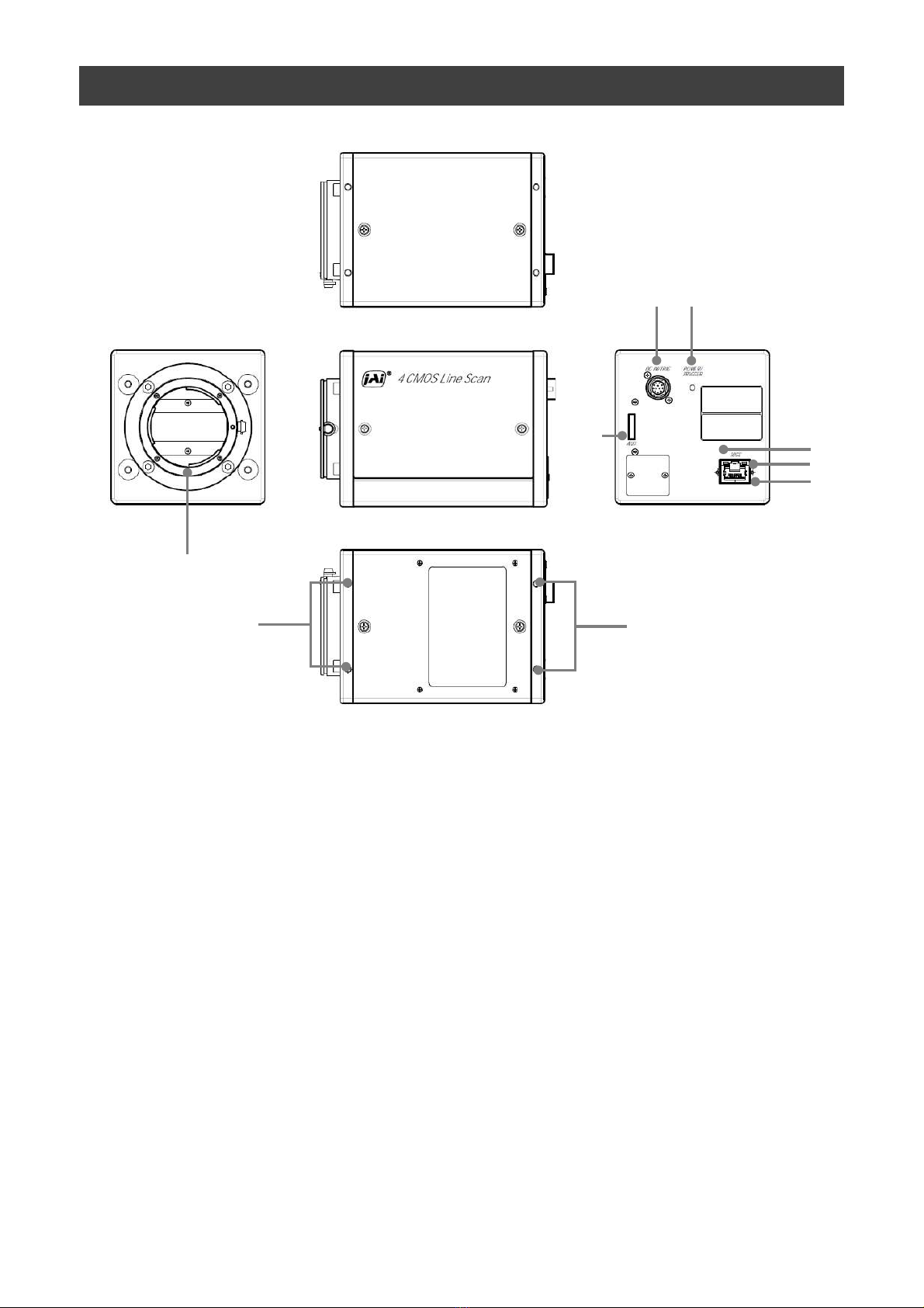
SW-4000Q-10GE
Secure manually.
Do not secure too tightly.
Notes on LAN cable connection
Secure the locking screws on the connector manually,
and do not use a driver. Do not secure the screws too
tightly. Doing so may wear down the screw threads
on the camera. (Tightening torque: 0.147 Nm or less)
Notes on temperature conditions
The guaranteed operating temperature and humidity of this camera are
-5℃ to +45℃, 20% to 80% (non-condensing).
Please make sure the following temperature condition is met when operating
the unit.
1) The camera's internal temperature sensor detects temperatures of 101 °C
or less during operation.
If the above temperature conditions are exceeded, take measures to dissipate
heat according to your installation environment and conditions.
Depending on the operating environment,
the surface of the camera may become very hot
during operation.
Do not touch the camera during operation and
while it is being cooled.
Also, make sure that the cable surface and other
easily deformable items do not contact the surface
of the camera.


-2076EN User manual")