BM-500CL / BB-500CL
- 3 -
- Contents -
1. General..................................................................................................... 5
2. Camera nomenclature ................................................................................... 5
3. Main Features ............................................................................................. 5
4. Locations and Functions................................................................................. 6
5. Pin Assignment............................................................................................ 7
5.1. 12-pin Multi-connector (DC-IN/Trigger)........................................................... 7
5.2. Digital Output Connector for Camera Link........................................................ 7
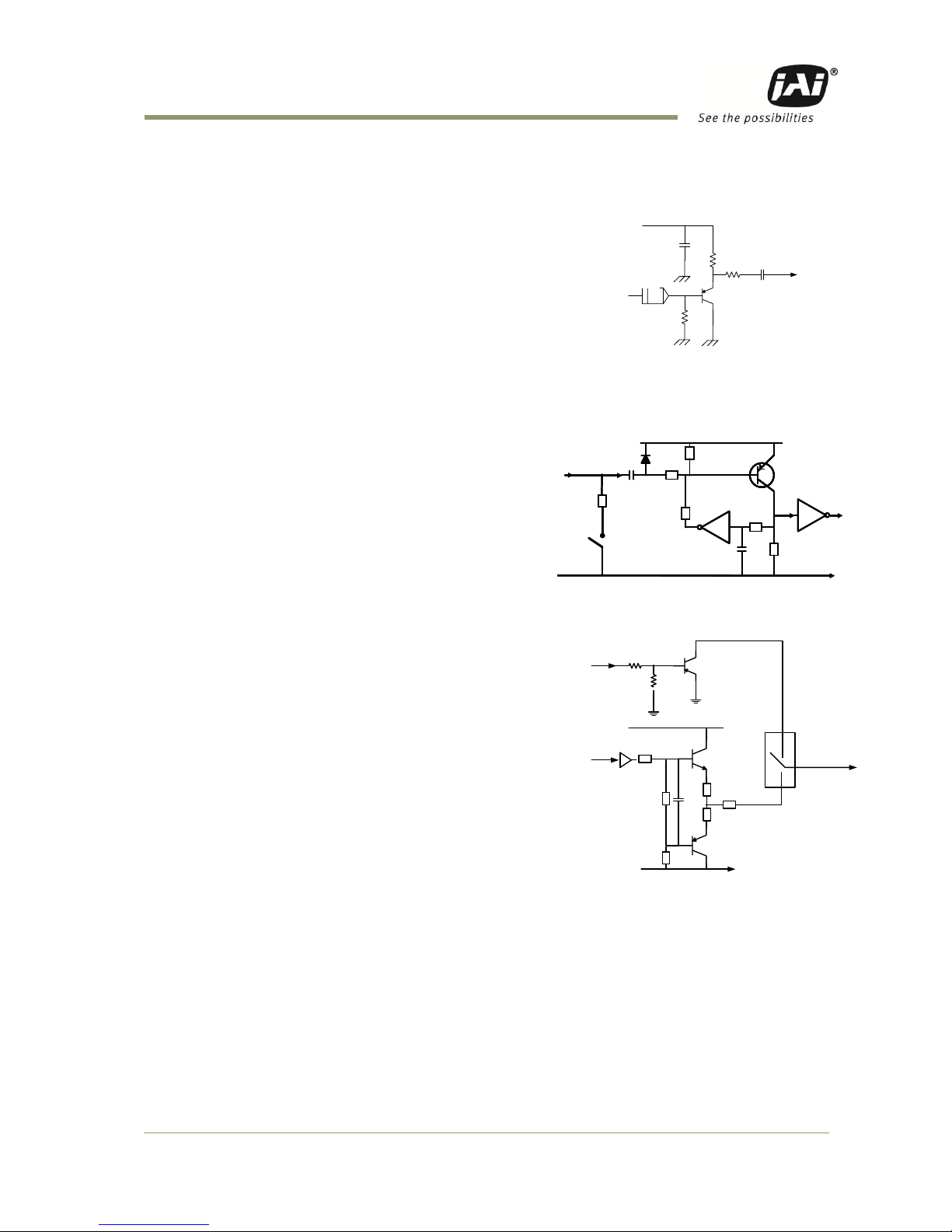
5.3. Input and output circuits ............................................................................ 8
5.3.1. Iris video output ............................................................................. 8
5.3.2. Trigger input ................................................................................. 8
5.3.3. XEEN output .................................................................................. 8
5.3.4. Camera Link interface ...................................................................... 9
6. Functions and Operations ..............................................................................10
6.1. Basic functions .......................................................................................10
6.1.1. Digital Video Output (Bit Allocation)....................................................10
6.1.2. Electronic Shutter ..........................................................................11
6.1.3. Continuous operation or triggered operation ..........................................11
6.1.4. Iris video output. ...........................................................................11
6.1.5. Rear panel indicator. ......................................................................12
6.1.6. Auto-detect LVAL-sync / a-sync accumulation ........................................12
6.1.7. Starting pixel - Bayer color mosaic ......................................................12
6.1.8. Partial Scanning ............................................................................13
6.1.9. Vertical Binning.............................................................................14
6.1.10. Decimation readout (Draft) mode .......................................................14
6.2. Pre-process functions ...............................................................................15
6.2.1. Bayer White Balance .......................................................................15
6.2.2. L/R channel balance .......................................................................15
6.2.3. Automatic output level controls .........................................................15
6.2.4. Programmable Look-Up Table (LUT) ....................................................16
6.2.5. Blemish Compensation circuit ............................................................16
6.3. Sensor Layout and timing...........................................................................17
6.3.1. CCD Sensor Layout .........................................................................17
6.3.2. Horizontal timing ...........................................................................18
6.3.3. Vertical timing ..............................................................................18
6.3.4. Partial Scan..................................................................................19
6.3.5. Vertical Binning.............................................................................20
6.3.6. Decimation readout (Draft) mode .......................................................21
6.4. Operation Modes .....................................................................................22
6.4.1. Continuous operation ......................................................................22
6.4.2. Pre-select Trigger Mode ...................................................................22
6.4.3. Pulse Width Trigger Mode .................................................................24
6.5. Mode and function matrix. .........................................................................25
7. Configuring the Camera ................................................................................26
7.1. DIP switch SW-800 ...................................................................................26
7.2. RS-232C control ......................................................................................26
7.3. Setting functions.....................................................................................27
7.3.1. Bit allocation. BA=0, BA=1, BA=2 .......................................................27
7.3.2. Partial scan. SC=0 through 4 / Draft mode SC=5 ......................................27
7.3.3. Variable (Programmable) Partial PRGP=0,1 , STL=2 to 2058, ETL = 2 to 2058...27
7.3.4. Vertical binning. VB=0, VB=1 ............................................................27
7.3.5. Shutter mode. SM=0 and SM=1 ...........................................................27
7.3.6. Trigger input select. TI=0, TI=1. .........................................................27