manuals.online logo
Brands
  1. Home
  2. •
  3. Brands
  4. •
  5. Jamara
  6. •
  7. Motorized Toy Car
  8. •
  9. Jamara Ultra BL 8 2,4 GHz User manual

Jamara Ultra BL 8 2,4 GHz User manual

Other manuals for Ultra BL 8 2,4 GHz

4

This manual suits for next models

1

Other Jamara Motorized Toy Car manuals

Jamara Bugatti Chiron User manual

Jamara

Jamara Bugatti Chiron User manual

Jamara Ferrari SF90 Stradale User manual

Jamara

Jamara Ferrari SF90 Stradale User manual

Jamara Dakar EP 2,4 GHz User manual

Jamara

Jamara Dakar EP 2,4 GHz User manual

Jamara Audi RS 6 User manual

Jamara

Jamara Audi RS 6 User manual

Jamara 404950 User manual

Jamara

Jamara 404950 User manual

Jamara Jeep Wrangler Rubicon Muddy User manual

Jamara

Jamara Jeep Wrangler Rubicon Muddy User manual

Jamara McLaren Senna 2,4GHz User manual

Jamara

Jamara McLaren Senna 2,4GHz User manual

Jamara SpyVi FPV User manual

Jamara

Jamara SpyVi FPV User manual

Jamara 410032 User manual

Jamara

Jamara 410032 User manual

Jamara BMW i8 User manual

Jamara

Jamara BMW i8 User manual

Jamara Mercedes-AMG GT R User manual

Jamara

Jamara Mercedes-AMG GT R User manual

Jamara 05 3290 User manual

Jamara

Jamara 05 3290 User manual

Jamara just play 460248 User manual

Jamara

Jamara just play 460248 User manual

Jamara Fendt 1050 Vario User manual

Jamara

Jamara Fendt 1050 Vario User manual

Jamara Power Drag Ride-On Traktor 12V User manual

Jamara

Jamara Power Drag Ride-On Traktor 12V User manual

Jamara 460274 User manual

Jamara

Jamara 460274 User manual

Jamara X2-CRT Sport RTR User manual

Jamara

Jamara X2-CRT Sport RTR User manual

Jamara Brecter Truggy User manual

Jamara

Jamara Brecter Truggy User manual

Jamara Lamborghini Murcielago LP 640-4 Roadster User manual

Jamara

Jamara Lamborghini Murcielago LP 640-4 Roadster User manual

Jamara 405173 User manual

Jamara

Jamara 405173 User manual

Jamara Jeep Wrangler JL User manual

Jamara

Jamara Jeep Wrangler JL User manual

Jamara J-ROCK User manual

Jamara

Jamara J-ROCK User manual

Jamara Ice Tiger EP BL User manual

Jamara

Jamara Ice Tiger EP BL User manual

Jamara Lamborghini Sian FKP 37 2,4GHz User manual

Jamara

Jamara Lamborghini Sian FKP 37 2,4GHz User manual

Popular Motorized Toy Car manuals by other brands

Reely Dune Fighter 3S operating instructions

Reely

Reely Dune Fighter 3S operating instructions

REVELL 1970 Chevelle SS 454 manual

REVELL

REVELL 1970 Chevelle SS 454 manual

Team Losi Micro Rally Car Operation guide

Team Losi

Team Losi Micro Rally Car Operation guide

Eduard Humber Scout Car Mk.I exterior quick start guide

Eduard

Eduard Humber Scout Car Mk.I exterior quick start guide

REVELL 68 CHEVY CHEVELLE SS 396 manual

REVELL

REVELL 68 CHEVY CHEVELLE SS 396 manual

Schumacher Pro Cat instruction manual

Schumacher

Schumacher Pro Cat instruction manual

Tamiya TT-01 TYPE E instruction manual

Tamiya

Tamiya TT-01 TYPE E instruction manual

Eduard Krupp Protze 6x4 1/48 quick start guide

Eduard

Eduard Krupp Protze 6x4 1/48 quick start guide

New Bright 61072UEP quick start guide

New Bright

New Bright 61072UEP quick start guide

Team Durango DEX410v5 manual

Team Durango

Team Durango DEX410v5 manual

PLAYMOBIL 9536 manual

PLAYMOBIL

PLAYMOBIL 9536 manual

Atomic BZ3 instruction manual

Atomic

Atomic BZ3 instruction manual

Aiyaplay 370-290V00 user manual

Aiyaplay

Aiyaplay 370-290V00 user manual

ZEROTRIBE Zetricks ZT1144 instruction manual

ZEROTRIBE

ZEROTRIBE Zetricks ZT1144 instruction manual

INJUSA 412 Assembly instructions

INJUSA

INJUSA 412 Assembly instructions

Maverick MSC-30BR-WP instruction manual

Maverick

Maverick MSC-30BR-WP instruction manual

Land of B. Rollin' Riders quick start guide

Land of B.

Land of B. Rollin' Riders quick start guide

TLR 22SCT 2.0 user manual

TLR

TLR 22SCT 2.0 user manual

manuals.online logo
manuals.online logoBrands
  • About & Mission
  • Contact us
  • Privacy Policy
  • Terms and Conditions

Copyright 2025 Manuals.Online. All Rights Reserved.

Ultra BL 8
2,4 GHz
No. 059730 BL Lipo
38/18
IT - Istruzioni di montaggio
GB - Instruction
IT - Informazioni generali
Jamara e. K. non e´responsabile per danni, sostenute al prodotto stesso o attraverso questo, dovuti
ad una gestione non corretta del articolo. Solo il cliente si assume la piena responsabilità per la
manutenzione e l´utilizzo corretto dello stesso; questo include il montaggio, la ricarica, l´utilizzo, 
no alla scelta della aerea di applicazione. Si prega di notare e rispettare le istruzioni d´uso, questi
contengono informazioni e avvertimenti molto importanti.
GB - General information
Jamara e.K. is not liable for any damage caused to the product itself or through this, provided this
is due to improper operation or handling errors. The Customer alone bears the full responsibility for
the proper use and handling, including without limitation, the assembly, the charging process, the
use and choice of the operation area. Please refer to the operating and user instructions, it contains
important information and warnings.
IT - Questo modello non é un giocattolo!
Sconsiliato per persone inferiori di 14 anni.
Attenzione: Non adatto a bambini di età inferiore a 36 mesi.
RISCHIO DI SOFFOCAMENTO!
Contiene piccoli pezzi che possono essere ingeriti.
Tenere sempre fuori dalla portata dei bambini.
This model is not a toy!
Not suitable for people under 14 year.
Warning: Not suitable for children under 36 months.
RISK OF SUFFOCATION!
Contains small parts which can be swallowed.
Keep away necessarily from children.
Attrezzi consigliati Recommended Tool
No. 19 0065
Misuratore convergenza
Camber adjusting Tool
No. 23 2060
Power Tape silicone
Doublesided power tape
No. 23 2423 medium
Lacca protezione
Nut lock
No. 23 0461 400 ml
Schiuma speciale Spray
Special cleaning foam
No. 50 5401 klein/small
Gra󰀨ette per carrozzeria
Body clips
No. 05 9273 1:10
Gra󰀨ette per carrozzeria
Body clips
No. 28 1787 Louise
Alesatore con indicazioni
misure e coperchio
Body reamer with cap and sizes
No. 15 3060
X-Peak 50 BAL
Caricatore
Charger
No. 28 1730
Lexanschere
Lexan scissors
No. 15 3055
X-Peak 80 BAL
Caricatore
Charger
No. 15 3058
X-Peak 80 BAL Pult
Caricatore
Charger
IT - Dichiarazione di conformità
Con la presente, l’azienda JAMARA e.K. dichiara che il modello “Ultra BL8 2,4 GHz,
No. 059730“ è conforme ai requisiti fondamentale e alle altre norme applicabili delle
Direttive 2014/35/UE, 2014/53/UE and 2011/65/UE.
Per ulteriori informazioni, consultare il sito web: www.jamara-shop.com/Conformity
GB - Certicate of Conformity
JAMARA e.K. hereby declares that “Ultra BL8 2,4 GHz, No. 059730“ follow the regulations and
requirements as well as any ther relivant directives of the EEC directive 2014/35/EU, 2014/53/EU
and 2011/65/EU. Further information can also be found at:
www.jamara-shop.com/Conformity
IT - Attenzione!
Prima dell‘uso: Accendete prima la trasmittente e poi il modello.
Dopo l‘uso: Spegnere prima il modello e poi la trasmittente.
●Non utilizzare il suo modello fuori della distanzia di vista. Sia la visibilità come la portata massima
del vostro modello dipendono da molti fattori, come il tempo, disturbo di frequenza e il luogo di
utilizzo. Eseguire un test prima di ogni utilizzo del modello con una seconda persona che tiene
ssato il modello. Con questa procedura potete testare come reagisce il modello durante la
perdita del segnale causato per esempio da una batterie scarica oppure la radio spenta.
Attention!
Before operating: Switch the transmitter on rst then the model.
When nished: First switch o󰀨 the model then the transmitter.
●Never operate your model beyond sight. Both the maximum visibility as well as the max. range
of your model will depend on many factors such as weather, location and interfering
frequencies. Therefore, before each use perform a range test with a second person securely
holding the model and also check how the model reacts if there is a signal failure e.g. when
empty transmitter batteries are installed.
IT - Prima di avviare il modello, leggere attentamente tutte le istruzioni per l’uso.
Attenzione! Leggere completamente le avvertenze / istruzioni di sicurezza,
questi sono per la vostra sicurezza può prevenire incidenti / infortuni.
GB - Read the complete instructions and security instructions carefully before using
the model.
Caution! Please fully and carefully read warnings/ safety instructions. These
are for our own security and can avoid accidents/injuries.
Questo prodotto è un articolo di modellismo. Ciò signica che il veicolo deve essere sempre sotto-
posto a manutenzione (controllare eventuali danni, controllare i collegamenti a vite, pulire ecc...).
Le parti soggette ad usura come l‘ingranaggio principale, il pignone del motore, bicchierino ecc.
si consumano nel tempo e devono pertanto essere sostituite. Non è sempre possibile evitare gli
incidenti, pertanto è necessario riparare o sostituire anche i danni causati dagli incidenti. Le parti
usurate o difettose a causa di urti o manutenzione insu󰀩ciente non sono coperte da garanzia, i
costi e le riparazioni sono a carico dell‘acquirente stesso.
This product is a model building article. This means that the vehicle must always be serviced
(check for damage, check screw connections, clean etc...). Wear parts such as the main gear,
motor pinion, bone socket, etc. will wear out over time and must therefore be replaced. Crashes
cannot always be avoided, so crash damage must also be repaired or replaced. Wear parts or
defective parts due to crashes or insu󰀩cient maintenance are not covered by warranty, costs and
repairs must be covered by the buyer himself.
Frequency bands: 2.4Ghz Frequency range: 2405,5 MHz - 2475,0 MHz EIRP: 49,09 mW (max. power transmitted)
2
IT - Avete acquistato un modello RTR. Ciò signica che il veicolo è in gran parte
pronto per l‘uso immediato. Tuttavia, è essenziale controllare che il modello non
presenti possibili danni meccanici o elettrici o difetti prima e dopo ogni utilizzo.
È inoltre necessario vericare la libertà di movimento di tutti gli elementi mobili e la
tenuta dei collegamenti a vite.
GB - You have purchased a RTR model, which means it should be ready for immediate use after
charging all batteries. You need to check the car, electronics and all plastic parts after each use to
make sure no parts are damaged. Also all the moving parts must be checked for their clearance,
bolts and screws that they are tight.
IT -
Informazioni relative alle pile:
Non ricaricare!
Non aprire!
Non gettare nel fuoco!
Non usare contemporaneamente pile nuove e pile usate!
Non usare contemporaneamente pile alcaline, standard (zinco-carbone) e ricaricabili!
GB -
Battery warning:
Do not recharge!
Do not open!
Do not dispose of in re!
Do not mix old and new batteries.
Do not mix alkaline batteries, standard (carbon-zinc) or rechargeable batteries.
LED
DE
● Per primo bisogna caricare la batteria.
1. Collegare il caricabatterie all’alimentazione CA. Il LED sul caricabatterie indica che è
pronto per la ricarica.
2. Collegare il caricabatterie alla batteria. Il LED cambia colore e indica il processo di
ricarica. Il processo di carica completo con batteria scarica dura ca. 5 ~ 7 ore, a secondo
della capacità della batteria. Quando il LED cambia di nuovo colore, la batteria è
completamente carica.
● Inserire 4 batterie AA nella trasmittente
● Leggere il capitolo sulla trasmittente.
GB
● The battery pack has to be charged before use.
1. Connect the charger to the AC Network and plug it into a grounding receptacle.
The LED on the charger will indicate it is ready for charging.
2. Connect the charger (B) to the battery pack (A). The LED will change the color to show it is
charging. If the battery pack is completely empty, a full charge process will take approx.
5 ~ 7 hours, depending on the batteries capacity. Once the LED changin the color again,
charge has been completed.
● Place 4 pieces of AA batteries into the transmitter.
● Read the chapter for usage of the transmitter and its controls carefully.
IT - Primi passi GB - Getting Started
IT - Attenzione!
Dopo ogni carica e importante di: Scollegare sempre subito la batteria dal
caricatore ed il caricatore dalla rete elettrica. Se dopo la carica si lascia
collegato l’uno o l’altro può causare danni alla batteria, al caricatore o
addirittura alla rete elettrica (pericolo di incendio).
GB - Danger!
Always disconnect the battery from the charger immediately after char-
ging. Always disconnect the charger from the power supply immediate-
ly after disconnecting the battery. Inserting the rechargeable battery or
charger after charging will result in damage to the battery, charger or the
power supply (re hazard).
IT - Lieferumfang
1. Modello
2. Telecomando
3. Antenna
4. Connettore di collegamento
5. Batteria
6. Caricatore
Accessori:
• Telecomando: 4 x AA 1,5V,
Nr. 14 0267 (4 pezzi)
Dati tecnici:
• Dimensioni:
~ 515 x 275 x 205 mm
• Peso: ~ 2360 g
• Batteria: LiPo 7,4 V 5000mAh
• Motor: 420W, 3000KV
Le informazioni non sono
garantite. Ci riserviamo il diritto di
apportare modiche tecniche e la
possibile presenza di errori.
GB - Box contents
1. Model
2. Transmitter
3. Antennas
4. Binding Plug
5. Battery
6. Charger
Accessories:
• Transmitter: 4 x AA 1,5V,
No. 14 0267 (4 pieces)
Technical data:
• Dimensions:
~ 515 x 275 x 205 mm
• Weight: ~ 2360 g
• Battery: LiPo 7,4 V 5000mAh
• Motor: 420W, 3000KV
No responsibility is taken for the
correctness of this information.
1
2
6
5
3
4
3
IT
Attenzione!
I dadi devono essere controllati prima del primo utilizzo e
periodicamente (3 -5 inserimenti) eventualmente riserrati.
Altrimenti, i dadi possono allentarsi a causa del alto ren-
dimento del motore al asse della ruota e la ruota potrebbe
staccarsi dal veicolo. Gravi danni púo provocare.
GB
Attention!
The wheel nuts must be checked and, if necessary, tightened
before the rst use and at regular intervals (3-5 uses). Other-
wise, the wheel nuts can come loose by the high power output
of the motor to the wheel axles and the wheel can be detached
from the vehicle. Serious damage can result.
50 5080
50 5081
07 9996
50 5079
50 5080
50 5081
07 9996
50 5079
IT
Attenzione!
Il veicolo è dotato di una Pivot sospensione anteriore. Questa
ha una serie di vantaggi. E ‚molto robusta e la manutenzione
e´molto facile. Questo è impostato in fabbrica in modo che la
carreggiata non permette agli cardani di saltare fuori. Come con
qualsiasi modello, dopo l´inizio dell’uso si rallentano
di qualche millimetro sia la sospensione sia i bulloni. Questo
gioco minimo, po’ abbastare sotto massimo sforzo per fare
saltare fuori i cardani. Pertanto
è necessario per assicurarsi prima di ogni uso che tutte le viti,
dadi, giochi ecc., sono ssate correttamente. La vita esterna
in plastica 505080 serva per ssare il fuso a snodo sulla vite a
sfera. Questo non deve essere serrata
troppo forte. In caso contrario, lo sterzo non si muove libera-
mente e la guida può essere inuenzata negativamente.
GB
Attention!
Your vehicle has a pivot front suspension. This has a number of
advantages. It is very robust and easy to maintain. The set-up of
the car has been done so the drive shaft will not pop out. As with
any model, screws and bolts can losen during break-in of the
car. This can result in tolerance of the drive shaft. The drive shaft
can then pop out if high pressure is applied. The inner ball screw
(item No.: 505081) will enable you to adjust the tolerance resul-
ting in ne adjustments of the track width. For best results when
setting up the pivot ball for the rst time, please always adjust
the upper and lower pivot in the same way. Fasten as far as the
pivot can still be pulled up and down easyly but not as far that it
will pop out if you give full steering angle. The outer plastic socket
screw (item No.: 505080) is only used for securing of the steering
knuckle. This should not be too tight, otherwise the steering is
not smooth and the handling can be adversely a󰀨ected.
IT - Attenzione.
Se il suo modello ha un interruttore On/O󰀨 e importante
spegnere il modello direttamente dopo ogni utilizzo. Se il
modello ha una batteria rimovibile oppure un connettore
alla batteria, si deve scollegare subito dopo ogni utilizzo dal
modello. Se la batteria rimane accesa oppure rimane colle-
gata essa si può scaricare. Una volta andata in sotto carica
la batteria perde potenza o può essere gravemente dann-
eggiata. In questo caso la batteria non si lascia più caricare
o scaricare ed esiste il pericolo d’in ammazione (pericolo di
incendio). Non provi mai a caricare o scaricare delle batteria sotto carice. La tensione
della batteria non deve mai essere sotto 6 Volt per evitare la scariche profonda. La
batteria completamente carica ha una tensione di circa 8,4 Volt. Dopo l‘uso, la batteria
intatta deve essere immediatamente completamente caricata, dopo una fase di
ra󰀨reddamento di min 10 minuti ma al più tardi dopo 12 ore, per prevenire la scarica
profonda attraverso l‘auto-scarica. Se la batteria non viene usata oppure messa in
stoccaggio è necessario controllare o ricaricata la batteria ogni 3 mesi, tensione
(volt 8). In caso di danneggiamento della batteria smaltire correttamente.
GB - Danger.
If your model has an on/ o󰀨 switch, always turn o󰀨 the model immediately after each
use. If your model has a removable battery or a disconnectable connector to the battery,
the battery should be disconnected from the model immediately after each use. The
battery can be deep-discharged by accidentally turning it on or by leaving the battery
plugged in. By deep discharge the battery it loses power, can be damaged so much that
charging or discharging is no longer possible and the battery can ignite itself during
charging or discharging (re hazard). Never attempt to charge or discharge deep-
discharge batteries.
The voltage of the battery should never be under 6 volt to avoid a deep discharge. The
fully charged battery has a voltage of 8,4 volt. After usage, the intact battery has to be
fully charged after a cooling phase of at least 10 min but not longer than 12 hrs. This
is to avoid a deep discharge caused by a self-discharge. When not using or storing
the battery it has to be checked at least every three months for voltage (min. 8 volt) or
damage and if necessary charged or disposed.
DE
● Mettete la batteria nel vano della batteria, a bordo del veicolo. Fare attenzione che la batteria
sia correttamente ssata con i 2 clip in dotazione e che la batteria non abbia un gioco
eccessivo nel vano appropriato.
● Ora collegare la batteria con il regolatore del modello. Se la spina del regolatore e la spina
della batteria non corrispondono, un cavo adattatore è incluso con il modello.
● Leggere il capitolo sulla trasmittente. Accendere la trasmittente e assicurarsi che i trim siano
in posizione neutrale
● Tenere il modello in aria per il caso che il motore si metta a girare a tutto gas.
● Ora accendere il regolatore di velocità tramite l`interruttore ON / OFF.
● Vi incoraggio ad attivare il ricevitore integrato in unità fail-safe.
Al momento della consegna è spento.
● Se questa è la tua prima auto rc, si consiglia di guidare su una pista piccola per familiarizzare
con il controllo del veicolo e i comandi del trasmettitore.
GB
● Put the battery into the battery holder in the vehicle. Make sure that the battery holder is scured
properly with the 2 included clips for the battery holder.
● Now connect the battery to the speed control in the model. If the plug of the speed control and
battery do not match, then you will nd a connection lead in your box
● Turn the radio on and make sure all the trim buttons on the transmitter are in neutral position.
Read the chapter for usage of the transmitter.
● Keep the car in the air in case that the motor turns at full power.
● Switch the speed control on the On / O󰀨 switch.
● We encourage you now to activate your receiver‘s built-in Failsafe unit.
On delivery it is turned o󰀨. (see chapter Fail Safe).
● If this is your rst rc car, we recommend to drive it on a small test track to familiarise yourself
with the control of the vehicle and the controls of the transmitter.
1
Regolatore
ESC
ON/OFF
Batteria
Battery
4
Motor
#A
#B
#C
ESC
Channel 2
Switch
Receiver
Channel 1
Servo
Plus pole
red cable
Minus pole
black cable
Set
ON/OFF
IT - Regolatore (installato) Versione BL
Dati tecnici:
Amperaggio 60 A
Mass. prestazione 390 A
Resistenza 0,0012 Ohm
Uso RC-Cars
Pacco batterie max. 2 LiPo-Zellen
Tensione BEC 6,0 V
Carico BEC 3A
Tipo motori sensorlose BL-Motoren
Sicurezza Übertemperaturschutz/Unterspan-
nungsabschaltung
Misure ~ 48,5 x 38 x 32 mm (mit Lüfter)
Peso ~ 90 g (ohne Anschlusskabel)
Programmabile 5 Programmierschritte (Bremse,
Unterspannung, Startmodus etc.)
GB - Controller (installed) Version BL
Technical data:
Max. Current 60 A
Burst Current 390 A
Internal Resistance 0,0012 Ohm
For Use With Cars or Trucks scale
Battery packs max. 2 LiPo cells
BEC Voltage 6,0 V
BEC Current 3A
Motor Types Sensorless Brushless motors
Protective Circuits Temperature cut-o󰀨
Size ~ 48,5 x 38 x 32 mm (with fan)
Weight 90 g (without cable)
Programmable 5 Programming steps (Break,
Low Voltage, Start Mode etc.)
L‘uso del regolatore
Collegamento della ricevente, la batteria e il motore
Collegare il regolatore, la ricevente, la batteria, il servo e il moto-
re in base alla seguente tabella. Prestare attenzione alla polarità
della batteria di alimentazione. Collegare il  lo rosso al terminale
‚+‘ e il nero con il „-“ della batteria. I terminali # ‚A‘ # # B e C‘ de-
vono essere collegati ai morsetti del motore. Il tasto ‚SET‘ viene
usato per la programmazione. Collegare l‘uscita del „canale 2“
della ricevente con il regolatore. Osservate l‘assegnazione dei
canali sul telecomando. Collegare le uscite del regolatore ai mor-
setti del motore. Non esiste un´assegnazione consigliata. Dopo
che tutto è collegato, è necessario di eseguire un test. Se il mo-
tore gira nella direzione sbagliata e consigliato di invertire i cavi
oppure veri care il tasto reverse sul radiocomando.
Nota
È possibile utilizzare la funzione inversa del radiocomando per
cambiare la direzione di rotazione del motore. È necessario di
riprogrammare il regolatore.
Using Your ESC
Connecting the Receiver, Battery Pack and Motor
Connect the ESC, the receiver, the battery pack, the steering
servo and the motor together following the diagram below.
Ensure that you observe the correct polarity of the battery pack.
The red cable should be connected to the ‘+‘ Plus Pole and the
black cable to the ‘-‘ Minus Pole. The ’#A’, ’#B’ and ’#C’ plugs
are connected to the motor. The ‘SET‘ button initiate the pro-
gramming mode. The ESC should be plugged into the throttle
channel of your receiver which is normally channel 2. If in doubt,
check your Radio- Control System’s instructions. The 3 Motor
wires can now be connected, these connectors can be plugged
in any order, and if the motor rotates in the wrong direction any 2
of the wires should be swapped.
Note:
You can use the servo reverse function of your transmitter to
reverse the motor direction but the ESC will have to be re-cali-
brated afterwards.
IT
Attenzione!
Il giunto omocinetico anteriore e posteriore assorbe la
maggior parte dell’energia del motore e lo passa all’asse
anteriore e posteriore. Per questo, le vite a brugola che tengono
il giunto omocinetico sul asse di uscita prima del primo utilizzo e
in intervalli regolari (5-7 inserti) devono essere controllati e se
necessario avvitare. Nel giunto omocinetico anteriore e pos-
teriore deve essere inserito un anello di gomma. Controllare il
gioco del albero motore. Il margine del gioco dovrebbe essere
di ca. 1-2 mm. Potrebbe essere necessario spostare il giunto
omocinetico per adattare il gioco. Qui deve svitare le vite senza
testa con un cacciavite e regolare il giunto omocinetico.
Dopo di che avvitare le vite senza testa. In caso contrario
l’omocinetico si sposta sul albero di uscita e l’omocinetico e
l’albero centrale possono essere danneggiati.
GB
Attention!
The front and rear bone pan absorbs most of the motor‘s
energy and directs it to the front and rear axles. Therefore,
the hexagon socket screws which hold the bone pans on the
transmission output shafts must be checked and, if necessary,
tightened before the rst use and in regular intervals e.g 5-7
uses. Insert a rubber ring to the front and the back connection
cup. Please check the tolerance of the drive shaft. The tole-
rance should be approx. 1 – 2mm. You may have to move the
connection cups to adapt the tolerance. Therefore you need to
loosen the grub screws to adapt the connection cup.
Afterwards tighten the grub screws. If not, the connection cups
will move on the gear output shaft. That might cause the con-
nection cup and the middle drive shaft to get damaged.
DE - Fernsteuerung 2,4 GHz 2CH GB - Transmitter 2,4 GHz 2CH
Vista laterale destra
1. Scatola di programmazione
2. Volante
3. Leva del gas
4. Vano Batterie
5. Presa di carica
6. Collegamentoper cavo Simulatore
Se si carica attraverso una presa, si prega di
aprire il coperchio della batteria. Viene usato
per il ra󰀨reddamento
Settore di programmzione
A. Direzione Reverse
B. Power LED
C. Direzione -Trim
D. Interruttore on /o󰀨
E. Gas Reverse
F. Power Check
G. Pulsante collegamen to Binde
H. Dual-Rate
I. Gas Trim
Trim
Se le ruote non puntano dritti in avanti, anche
se il volante della trasmettente è in posizione
neutrale, è possibile ottenere aiuto con il trim
della trasmittente nella posizione corretta.
Trim L/R = Sterzo
Se le ruote girano in avanti o indietro, anche se
nessun comando è stato dato attraverso il tras-
mettitore, poi anche l‘acceleratore deve essere
tagliato sul trasmettitore.
Trim V/R = Avanti / Indietro
Inserimento delle batterie
• Togliere il coperchio del scomparto batterie.
• Inserire 4 x AA batterie nella giusta
posizione, facendo attenzione ai poli.
• Rimettere il coperchio del scomparto
batterie.
GB - Controls
1. Programming Box
2. Steering Wheel
3. Throttle Lever
4. Battery Hatch
5. Charge Socket
6. Simulator Cable Socket
If charging the batteries via the charging socket,
the battery hatch cover should be removed to
ensure su󰀩cient cooling.
Programming Panel
A. Steering Reverse (changed)
B. Power LED
C. Steering Trim
D. ON/OFF Switch
E. Throttle Reverse (changed)
F. Power Check
G. Binding Button
H. Dual-Rate (maximum steering deection)
I. Throttle Trim
Trim
If the wheels do not point straight forward even
though the steering wheel on the transmitter is
in neutral, you can adjust it with the trim button
on the transmitter.
Trim L/R = steering
Should the wheels rotate forward or backward,
even though no command was given through
the transmitter, then also the throttle needs to
be trimmed on the transmitter.
Trim V/R = forward/backward
Insert the batteries
• Remove the battery compartment cover.
• Fit the 4 x AA batteries, observe the correct
polarity.
• Replace the battery hatch
C
A
B
D
E
G
H
F
I
6
12
3
4
5
5
Apprendimento della corsa gas / freno
Per prestazioni ottimali, il regolatore deve essere calibrato. In tal modo, le tre
posizioni avanti, indietro e la posizione di folle devono essere specicata.
Durante la regolazione procedere come segue:
1. Accendete il radiocomando, durante che la ricevente è spento. (Attenzione con sistema di
Futaba: In certi casi la funzione del gas è invertita). La corsa servo deve essere in posizione
neutrale. Fare attenzione che la funziona ABS sia spenta.
2. Poi accendere la ricevente tramite l‘interruttore sul regolatore. Tenendo premuto il tasto ‚SET‘.
Questo vi porterà alla modalità di calibrazione, il LED inizia a lampeggiare. Appena il LED
lampeggia, rilasciare il pulsante. Se non si rilascia il tasto ‚SET‘ subito dopo il LED inizia a
lampeggiare e si entra nella modalità di programmazione. Se non si desidera questo, è
necessario a spegnere nuovamente il regolatore. La gura seguente mostra il processo d’inizio
di calibratura.
3. E´possibile congurare tre parametri:
Posizione neutra, Fine corsa marcia avanti, Fine corsa marcia indietro
4. Portare la leva del gas in posizione neutrale e premere il tasto ‚SET‘, il
LED verde lampeggia una volta e il motore emette un suono. Portare la leva del gas in posizione
nale per il movimento in avanti e premere il tasto `SET il LED verde lampeggia due volte e il
motore emette due suoni. Portare la leva del gas in posizione nale per il movimento indietro
e premere il tasto `SET`, il LED verde lampeggia tre volte e il motore emette tre suoni. Attendere
tre secondi, dopodiché è terminato il processo di calibrazione.
Throttle range calibration
To ensure that your ESC operates correctly it has to be calibrated. During this process the full
throttle, stop and brake positions will be set.
To calibrate the system, please proceed as follows:
1. Switch ON the transmitter. The throw should be set to neutral. If the transmitter is tted with an
ABS function this must be de-activated.
2. Press and hold down the ‘SET‘ button on the ESC and switch the receiver switch ON. The
LED will begin to blink. If you fail to release the
‘SET’ button the ESC will enter ‘Programming’ mode. If this
happens, you will have to switch the ESC o󰀨 and start again to enter ‘Calibration’ mode.
3. Parameters can be set here:
Neutral point, Full throttle forwards, Full throttle reverse
4. Ensure that the throttle control is in the neutral position and press the ‘Set‘ button. The green
LED will ash once and the motor will omit a beep. Move the throttle control to the full throttle
(forwards) position and press the green ‘Set‘ button. The green LED will ash twice and the
motor will omit 2 bleeps. Move the throttle control to the full reverse position and press the
‘Set‘ button. The green LED will ash 3 times and the motor will omit 3 bleeps. 3 Seconds after
this procedure has been followed, the motor is ready for use.
Gusto presa sul SET Stampato interruttore Lasciate che il pulsante SET quando
le luci rosse lampeggiano crostate
Hold the SET keep button Turn on the switch Release the SET button as soon
as the red LEDstarts to blink
ON/OFF
1
ON/OFF
Set LED
Neutral point
rst click second click third click
Point of full throttle Point of full brake
2
LED verde
lampeggia una volta
Green LED ashes
once
LED verde
lampeggia due volte
Green LED
ashes twice
LED verde
lampeggia tre volte
Green LED
ashes thrice
Set
Set Set
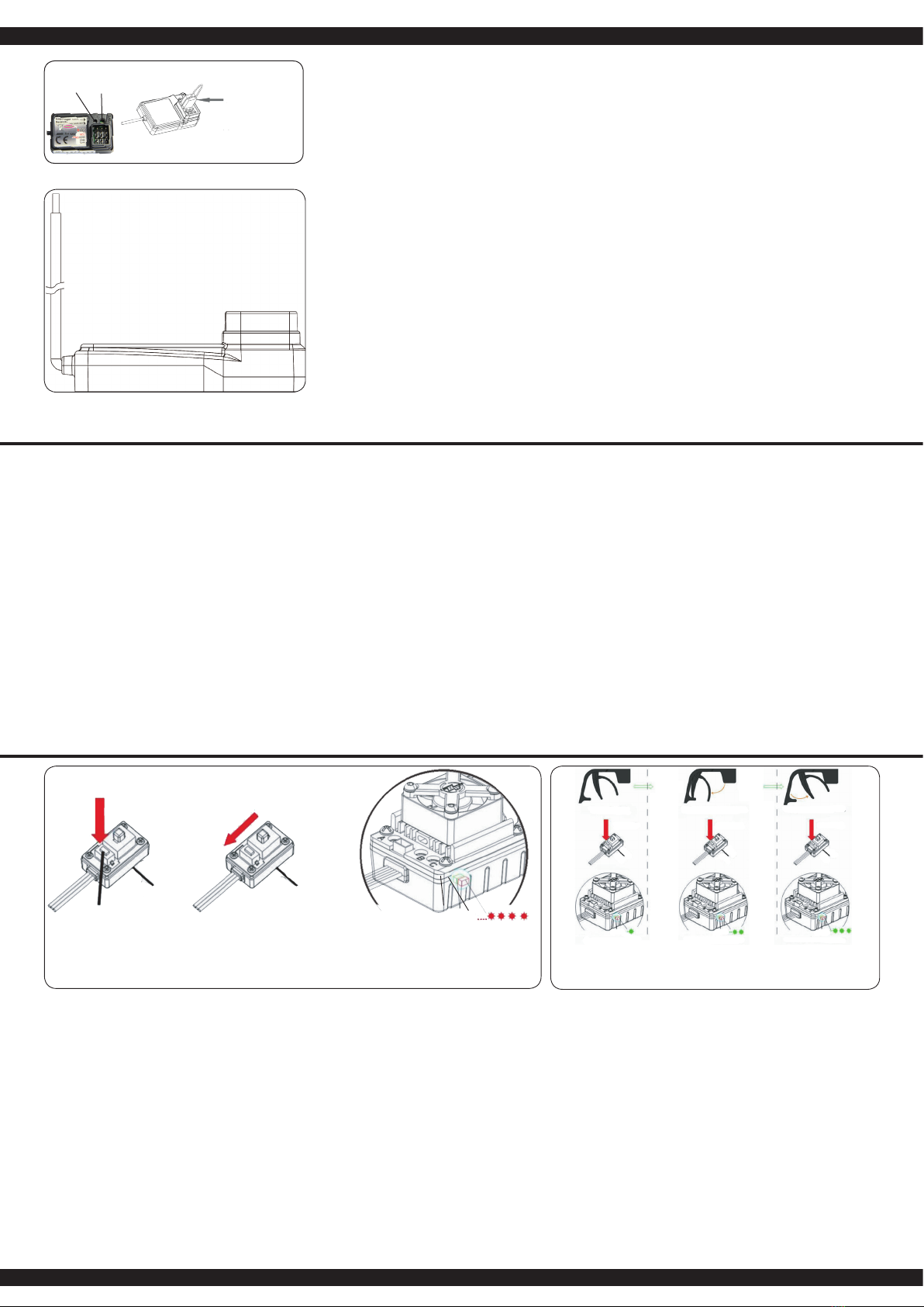
IT - Allacciare la trasmittente alla ricevente
In un moderno sistema di 2,4 GHz, è indispensabile che la tras-
mittente e la ricevente vengano connesse insieme a bordo del
modello. La ricevente accetta quindi solo i segnali della trasmit-
tente. Se per qualsiasi motivo si dovesse e󰀨ettuare un nuovo
allacciamento“connessione”, eseguire le seguenti operazioni:
A. Sostituire nella trasmettente le batterie scariche con altre
cariche o nuove. Lasciare spenta la trasmettente.
B. Inserire la spina di accoppiamento in dotazione nell’uscita
del canale 3.
C. Collegando la batteria con la ricevente, si accende il sistema
ricevente. Secondo la versione di software usata, la
ricevente segnala in modo di󰀨erente la modalità di
binding. (esempio: il Led può lampeggiare, restare
accesa o completamente spenta). Il processo di binding in
se è uguale per tutte le versioni. Il Led sulla ricevente inizia
lampeggiare e cosisegnala che la ricevente si trova in
modalità di binding.
D. Tenere premuto il pulsante di connessione sulla
trasmittente, mentre si accende la stessa.
E. Il trasmittente inizia a lampeggiare e cosi segnala che si
trova in modalità di binding.
F. Rilasciare il pulsante di connessione della trasmettente e
rimuovere la spina di connessione nella ricevente. Spegnere
laricevente e la trasmittente.
G. Adesso spegnete la trasmittente. Il sistema memorizza il
collegamento.
H. Installare correttamente tutti gli accessori e controllare con
molta attenzione.
I. Se la funzione non avesse successo, ripetere la procedura
di connessione.
L’illustrazione seguente mostra gra camente il processo di con-
nessione e speci ca gli elementi da utilizzare.
GB - Binding the receiver to the transmitter
As with all modern 2.4GHz R/C systems the receiver must be
bound to the transmitter to ensure that the receiver will only react
to signals from that transmitter.
If you wish to re-bind the receiver with the transmitter please pro-
ceed as follows:
A. Ensure that the transmitter is tted with fresh or fully charged
batteries and leave the transmitter o󰀨.
B. Plug the binding plug (included) into the channel 3 socket on
the receiver.
C. Switch the receiver system on by connecting the battery or
turn in a BEC operating on a controller to control. Depen-
ding on your software version of your receiver indicates
the di󰀨erent binding mode (instead of ashing lights for
example LED or remains out completely). The binding
process as such is in all versions. The receiver LED will be-
gin to ash indicating that the receiver is in bonding mode.
D. Press and hold down the binding button on the transmitter
whilst switching it on.
E. The transmitter will begin to ash indicating that the receiver
is in bonding mode.
F. Release the binding button on the transmitter and discon-
nect the receiver from the battery or turn o󰀨 the controller.
Release the binding plug from the receiver.
G. Switch of the transmitter. And remove the binding wire. The
system be bound at the next start .
H. Install all properly and check anything very precisely.
I. If the receiver fails to bond or does not function after bond-
ing repeat the above procedure until a successful bonding is
achieved.
The diagram illustrate the bonding process and show the loca-
tions of the relevant components.
Programmazione del gruppo integrato di FailSafe
1. Descrizione della Funzione
L’unità FailSafe è concepita principalmente per l‘utilizzo sulle imbarcazioni e sui veicoli. Serve
per evitare la perdita del modello, determinando la chiusura del gas, nell’eventuale assenza
di segnale. Se la ricevente perde il segnale della trasmittente, il servo del gas o regolatore di
velocità ritorna automaticamente sulla posizione programmata inizialmente.
2. Impostazione
a. Accendere la trasmittente
b. Accendere la ricevente. Il segnale LED lampeggia continuamente e indica che la ricevente
è pronta.
c. Spostare sul trasmettitore la leva dell‘acceleratore nella posizione di freno, o zona spento
nel regolatore di velocità. Tenere la leva del gas su questa zona.
d. Premere il pulsante Imposta sul ricevitore. Il segnale LED lampeggia per 3 secondi (vedi
illustrazione a sinistra).
e. L‘impostazione è salvata e si può portare la leva dell’acceleratore in posizione neutra.
3. Prova delle impostazioni
a. Accendere la trasmittente.
b. Accendere la ricevente.
c. Spegnere la trasmittente.
d. Ora la ricevente perde il segnale e conduce il servo del canale gas o il regolatore di
velocità sulla posizione in precedenza programmata.
e. Seguire la procedura descritta sopra, il processo FailSafe funziona correttamente.
How to setup the fail safe function
1. The instruction of function
The function of protection of losing control is mainly for r/c boats and cars and keeps them
away from damage through throttle channel. When the receiver is out of control signal, the
receiver of throttle will automatically return to the initial position which set up before starting to
avoid the error action :
2. How to set the function
a. Switch on the transmitter power and enter into the working condition
b. Connect the receiver with power and enter into the working condition, the signal light on
receiver will blink
all the time.
c. Control the throttle of transmitter and keeps the servo or ESC in the neutral position.
d. Press the setting button, the LED will be ash for 3 seconds (see on pict. left).
e. Release the setting button. The setting is nished.
3. Testing
a. Switch on the transmitter and enter the working condition.
b. Contact the receiver with power and enter the working condition.
c. Turn o󰀨 the power of transmitter.
d. The throttle of servo will be set automatically.
e. Finish these steps above means the setting is ok.
Bindungsstecker
Binding Plug
Fail Safe
Setup LED
2,4 GHz
Antenne
Antenna
Empfänger/Receiver
6
Le caselle grigie indicano l’impostazione consigliata. The elds which are shaded in grey indicate the factory recommended settings.
IT - Programmazione del regolatore GB - Programming the ESC
Fase di programmazione
Program Mode
Valori del programma
Program Value
1 2 3 4 5 6 7 8
1. Modalità di guida
Drive Mode
In avanti freno on
Forwards, brake on
avanti / indietro,
freno on
forwards / reverse,
brake on
2. Freno
Drag Brake Force
0 % 5 % 10 % 15 % 20 % 25 % 30 % 40 %
3. Sottotensione
Low Voltage
aus
OFF
2,6 V/Zelle
2,6 V/cell
2,8 V/celle
2,8 V/cell
3,0 V/celle
3,0 V/cell
3,2 V/celle
3,2 V/cell
3,4 V/celle
3,4 V/cell
4. Start modo
Start Mode
sanft
soft
normal
normal
aggressivo
aggressive
molto aggressivo
very aggressive
5. Forza frenante massima
Brake Max.
25% 50% 75% 100%
IT
Questo regolatore è dotato di numerose opzioni di congurazione. Per raggiungere il Suo obiettivo
di programmazione ottimale in modo rapido e sicuro, si tiene fede al menu mostrato nella struttura
della tabella sopra e le opzioni di programmazione. Le singole fasi di programmazione della tabella
hanno i seguenti signicati:
1. Modalita´di guida
Nel modo gara punto 1, il veicolo sta viaggiando solo in avanti, il freno e´attivato, la marcia
inversa e´escluso. Questa modalità è adatta per le competizioni. In modalità di guida, punto 2
(avanti / indietro con freno), il veicolo può anche invertire con funzione freno attivato. Questa
modalità è adatta per le operazioni normali e per principianti.
Nota:
Nella 2.modalità di guida, è necessario confermare l´operazione due volte per avere l´e󰀨etto
d’inversione. Se si passa la leva in avanti, per la prima volta nella zona inversa, il motore
frena. Il veicolo si ferma, ma non totalmente. Ora, se la leva viene premuto nuovamente
nella zona inversa, inverte il veicolo, pero prima si ferma brevemente. Quando la leva viene
nuovamente spostato in avanti, indipendente se il motore è in frenata o in modalità inversa, la
macchina poi viaggia nuovamente in avanti.
2. Freno:
In questo menu, l‘azione minimo di frenatura del freno, viene impostato come valore. Il campo
di regolazione è compreso tra 0 e 40%.
3. Sottotensione
In questo punto po’ essere impostato il valore di spegnimento. L‘intervallo d’impostazione è
tra 3,4 - 2,6 V per cella. Appena è superata la soglia, il regolatore spegne il motore.
4. Start-Modus:
Con questa opzione è possibile impostare come deve essere eseguito la partenza. C’è la
possibilità di scegliere tra 4 modi, diversi, da delicato a molto aggressivo. Si noti che per le
modalità „aggressivo e molto aggressivo“ si deve usare batterie particolarmente potenti con
bassa resistenza interna. In caso contrario, avvengono sottotensione e il motore gira su solo
con ritardo. Inoltre, il motore e la trasmissione sono da regolare, secondo la modalità di
avviamento desiderata.
5. Forza frenante massima:
Il regolatore è dotato di un freno che agisce proporzionale alla posizione della datrice. Il più
forte e󰀨etto si ottiene quando la leva viene spinto completamente in avanti. Un forte e󰀨etto
frenante porta il veicolo a un arresto rapido, che d‘altra parte, è collegato a un elevato grado
di usura dei parti meccanici come per esempio l´ingranaggio.
GB
This ESC is tted with many useful functions and to help you to be able to make the most of the
various options they are explained below. Please use the programming table shown on page 6
together with these explanations to program your ESC quickly and e󰀨ectively:
1. Drive mode:
If option 1 is selected in Drive mode, the vehicle will only drive forwards and the brake is
active which make this mode the best choice for racing. In mode 2 the vehicle can be driven
forwards or in reverse and the brake is also active. This mode is useful for general use and
training.
Note:
When option 2 is selected, moving the throttle control back past the neutral point will initially
activate the brake. If the throttle control is then moved back to the neutral position briey the
ESC will switch over to reverse. Moving the ESC forwards will make the vehicle drive
forwards regardless of whether it was braking or moving in reverse.
2. Drag Brake force:
In this option the drag braking force can be set. The value is set as a percentage and the
values are from 0 to 40%
3. Low voltage:
In this option you can set the low voltage cut-o󰀨 value. The cut-o󰀨 voltage can be set between
3.4 and 2.6 Volts per cell. Once the cut-o󰀨 voltage has been reached the motor will stop.
4. Start Mode:
With this option you can choose how the vehicle will accele rate when full throttle is applied
and you can set the value between ‘Soft‘ and ‘Very Aggressive‘. Please note that if you select
one of the 2 ‘Aggressive’ modes that you will need to have batteries with a very low internal
resistance otherwise the voltage will drop due to the high current draw and the motor may
stutter. Also ensure that your motor and gearing are capable of carrying the high loads.
5. Brake Max.:
The ESC is equipped with a braking system which works proportionally to the throttle control.
This means that the further the throttle control is moved rearwards the more braking force will
be applied. A higher value here will mean that the vehicle will brake harder but more strain will
be placed on the components, for example, the gearing.
DE - Signale und Schutzeinrichtungen
Während des normalen Betriebsmodus haben die LED-Signale folgende Bedeutung:
a. Keine LED = Gasgeber in der Neutralposition
b. Rote LED = Fahrzeug bewegt sich vor- oder rückwärts
c. Grüne LED = Gasgeber bendet sich in der max. Vor- oder Rückwärtsposition
Durch Warnsignale macht der Regler auf bestimmte Zustände aufmerksam:
1. Beim Einschalten überprüft der Prozessor die Eingangsspannung, wenn sie außerhalb der
zulässigen Grenzen liegt, ertönt ein Signal mit einer Sekunde Pause, zwischen den einzel-
nen Signalen “beep-beep-, beep-beep-, beep-beep-”
2. Wenn das Eingangssignal nicht ordnungsgemäß ist, ertönt ein Signal mit zwei Sekunden
Pause, zwischen den einzelnen Signalen “beep-, beep-, beep-”. Dieser Regler ist mit einer
Reihe von Schutzeinrichtungen für einen sicheren Betrieb ausgestattet:
1. Unterspannungsabschaltung:
Sobald die Spannungslage eines LiPo-Akkus für eine Zeit von 2 Sek. die eingestellte
Schwelle unterschreitet, wird der Motor abgeschaltet. Beachten Sie, dass der Motor nicht
wieder gestartet werden kann, wenn sich die Spannung unterhalb des voreingestellten
Wertes bendet.
2. Übertemperaturabschaltung
Sobald die Temperatur des Reglers, für eine Dauer von 5 Sek., den Wert von 95°C über-
schreitet, wird der Motor abgeschaltet. Nach dem Abschalten müssen Sie den Regler
unbedingt abkühlen lassen, da der Regler sonst beschädigt wird. Diese Funkton darf nicht
deaktiviert werden!
3. Fehlerhaftes Eingangssignal
Sollte das Eingangssignal für eine Zeitdauer von 0,2 Sek. als nicht ordnungsgemäß erkannt
werden, wird der Motor abgeschaltet.
IT - Segnali e dispositivi di sicurezza
Durante il normale funzionamento, i segnali LED hanno i seguenti signicati:
a. Quando l‘acceleratore è in posizione neutra, non è accesa né la LED rossa né la LED verde.
b. Il LED rosso si accende quando il veicolo è in movimento in avanti o indietro. Durante la
frenata, il LED rosso lampeggia velocemente.
c. I LED verde si accende quando il generatore di gas e in max. posizione avanti o indietro.
Tramite segnali d’avviso, il regolatore richiama l‘attenzione su determinate condizioni:
1. Durante l´avvio, il processore controlla la tensione d’ingresso, quando è al di fuori dei limiti
consentiti, un tono duale con una pausa di un secondo tra i singoli segnali „bipbip, bip-bip,
bip-bip-“ lo segnala.
2. Quando il segnale d’ingresso non è corretto, sarà generato un suono con una pausa di due
secondi tra i singoli segnali „bip-,-bip, bip-“ Questo regolatore è dotato di una serie di dispositivi
di sicurezza per un funzionamento sicuro:
1. Spegnimento sottotensione:
Non appena la tensione di una batteria LiPo, per un periodo di 2 secondi, va sotto la soglia
impostata, il motore si spegne. Notate che il motore non può essere riavviato, se la tensione di
una cella è inferiore a 3,5 V. Batterie NiCd o NiMH con una tensione compresa tra 9,0 V e
12,0 V, sono trattate come una batteria LiPo a tre celle. Le batterie con meno di 9.0 V come un
due-celle LiPo-Pack. Se per esempio, una batteria NiMH ha una tensione di 8,0 V, e la soglia
è impostata a 2,6 V per cella LiPo, l‘arresto avviene a 5,2 V (2 x 2,6 V). Cosi anche le celle di
NiCd, sono e󰀩cacemente protetti contro una scarica profonda.
2. Spegnimento per sovratemperatura:
Appena la temperatura del regolatore, per una durata di 5 secondi, supera il valore di 95 ° C, il
motore si spegne. Dopo lo spegnimento, è necessario lasciare ra󰀨reddare il regolatore,
altrimenti il regolatore sarà danneggiato. Questa funzione non può essere disabilitata!
3. Segnale d´ingresso difettoso:
Se il segnale d’ingresso per un periodo di 0,2 sec è rilevato come errato e motore si spegne.
7
Nota importante:
Oltre ai segnali lampeggianti del LED rosso, sono generati anche segnali acustici dal motore. Al
termine di ogniprogrammazione, il regolatore deve essere prima spento. Dopo il riavvio, la nuova
congurazione avrà e󰀨etto.
Important note:
In addition to the red LED blinking, the motor will omit an acoustic signal. After every change to
the values the ESC must be switched o󰀨 to store the values. The new settings will not be e󰀨ective
until the ESC is re-started.
IT - Struttura del menu del regolatore GB - Menu structure
Accendere il regolatore, mentre si
preme il tasto ‚SET‘.
Press and hold the ‘SET‘ button
down and switch the receiver on
Il LED rosso lampeggia
The red LED blinks
Accendere il trasmettitore
Switch transmitter ON
Il LED verde lampeggia una volta
The green LED blinks once
Il LED verde lampeggia 2 x
The green LED blinks twice
Il LED verde lampeggia 3 x
The green LED blinks 3 times
Il LED verde lampeggia X x
The green LED blinks X times
Premere il
pulsante
per 3 secondi
Press the button
for 3 seconds
Premere il
pulsante
per 3 secondi
Press the button
for 3 seconds
Premere il
pulsante
per 3 secondi
Press the button
for 3 seconds
Lasciare il tasto
Release button
Lasciare il tasto
Release button
Lasciare il tasto
Release button
Lasciare il tasto
Release button
Premere il
tasto
Press button
Premere il
tasto
Press button
Premere il
tasto
Press button
Premere il tasto
Press button
Programmazione Fase 1,
modalità di guida
Program option 1, Drive mode
Fase di programmazione 2,
modalità di frenata
Program option 2, Brake mode
Fase di programmazione 3,
sottotensione
Program option 3, Low voltage cut-o󰀨
Phase de programmation X
Program Option
Il LED rosso lampeggia una volta, cioè, signica andare avanti con
freno. Red LED blinks once indicating forwards and brake.
rote LED blinkt zweimal, d.h. Vorwärts- und Rückwärtsfahrt mit Bremse
The red LED blinks twice indicating forwards, reverse and brake.
rosso|red LED lampeggia|blinks 1x, ►0 %
rosso|red LED lampeggia|blinks 2x, ►5 %
rosso|red LED lampeggia|blinks 3x, ►10 %
rosso|red LED lampeggia|blinks 4x, ►15 %
rosso|red LED lampeggia|blinks 5x, ►20 %
rosso|red LED lampeggia|blinks 6x, ►25 %
rosso|red LED lampeggia|blinks 7x, ►30 %
rosso|red LED lampeggia|blinks 8x, ►40 %
rosso|red LED lampeggia|blinks 1x, ►aus
rosso|red LED lampeggia|blinks 2x, ►2,6 V
rosso|red LED lampeggia|blinks 3x, ►2,8 V
rosso|red LED lampeggia|blinks 4x, ►3 V
rosso|red LED lampeggia|blinks 5x, ►3,2 V
rosso|red LED lampeggia|blinks 6x, ►3,4 V
Si prega di premere il tasto ‚SET‘ per ogni modica del valore corrente,
il LED rosso indica ciascuno dei valori, lampeggiare una volta signica
che è impostato su valore 1, due volte sul valore 2 ecc.
Press the ‘SET‘ button to select the desired value. The red LED will
indicate which value is selected. 1 X blink indicates value 1, 2 x blinks
indicate value 2 etc.
Tutte le fasi seguenti di programmazione si svolgano nella stessa maniera.
All of the other menu options are accessed in the same manner.
8
IT - Risoluzione dei problemi
Modello non risponde
1. Batterie scariche o difettose
- Caricare, sostituire le batterie
2. Motore difettoso
- Sostituire il motore
3. Cavi allentato o danneggiato
- Ricollegare o sostituire i cavi
4. Trasmettente spenta, danneggiato o perso il binding
- Accendere la trasmittente o rie󰀨ettuare il binding
5. Ricevente di󰀨ettoso
- Sostituire la ricevente
6. Regolatore di velocità difettoso oppure non
correttamente collegato
- Sostituire oppure ricollegare il regolatore
Modello reagisce in maniera incontrollata
1. Trasmettente spenta, danneggiato o perso il binding
- Accendere la trasmittente o rie󰀨ettuare il binding
2. Regolatore programmato non correttamente
- Riprogrammare il regolatore
3. Ricevente di󰀨ettosa
- Sostituire la ricevente
Motore reagisce in modo strano appena acceso la
trasmittente
1. Fail Safe male impostato
- Riprogrammare il Fail Safe
2. Trim del Gas non in posizione neutrale
- Trimmare il Gas
Modello va solo in avanti
1. Regolatore programmato non correttamente
- Riprogrammare il regolatore
Reagisce solo il sterzo ai comandi
1. Regolatore oppure motore di󰀨ettoso
- Sostituire il regolatore oppure motore
Sterzo non risponde
1. Servo sterzo di󰀨ettoso
- Sostituire il servo sterzo
2. Dualrate non impostato correttamente
- Impostare Dualrate
3. Leva del sterzo sporco
- Pulire la leva del sterzo
Forte rumore dalla trasmissione
1. Ingranaggio principale, pignone o di󰀨erenziale
danneggiati
- Non continuare la guida! Sostituire la parte difettosa
2. Distanza pignone corona non impostata bene
- Controllare il giocho tra pignone - corona
Regolatore di velocità si spegne durante la guida
1. Blocco della sottotensione, tensione batteria bassa
- Caricare la batteria
2. Spegnimento per temperatura eccessiva
- Fare ra󰀨reddare il regolatore di velocità
Perdita dei cardani anteriore
1. Larghezza carreggiata elevata
- Riduree la distanza
GB -
Model does not respond
1. Battery or batteries empty or defective
- Charge battery or replace
2. Motor broken
- Replace motor
3. Loose or damaged cable
- Reconnect cable or replace
4. Transmitter turned o󰀨, lost or damaged binding
- Transmitter back on, bind or replace
5. Defective receiver
- Replace receiver
6. Speed controller is defective or connection issue
- Connect properly or replace
Model react uncontrolled
1. Transmitter turned o󰀨, lost or damaged binding
- Transmitter back on, bind or replace
2. Controller not calibrated or programmed incorrectly
- Recalibrate or reprogram
3. Defective receiver
- Replace receiver
Engine is running when you turn on inadvertently
1. Incorrectly set Failsafe
- Failsafe program to neutral
2. Throttle trim on the transmitter is not in neutral
- Throttle trim set to neutral
Model moves forward only
1. Controller not calibrated or programmed incorrectly
- Recalibrate or reprogram
Only steering response
1. Regulator or Motor is defective or not Calibrated
- Calibrate speed controller or replace motor
Steering does not respond
1. Power steering defect
- Replace servo
2. Dual Rate on the transmitter set too low or to 0
- Dual rate increase
3. Very dirty steering lever or steering knuckle -
Clean and lubricate well
Loud noise from the drive
1. Main gear, pinion or di󰀨erential damage
- Do not continue! a󰀨ected part needs to be replaced
2. Incorrect gear mesh
- Reset gear mesh
Speed controller shuts o󰀨 while driving
1. Low voltage cut-o󰀨, battery voltage too low
- Charging the battery
2. Overtemperature
- Let speed controller cool
Front drive shafts fall out
1. Too large track width
- Track width reduction
9
di󰀨erenziale di montaggio
Di󰀨erential assembly 07 9989
07 9989
505074
50 5071
50 5071
50 5071
50 5073
50 5071
50 5085
50 5085
505155
50 5085
Montaggio di trasmissione anteriore
Front gearbox assembly
50 5058
05 9106
17 7463
05 9096
05 9097
50 5078
50 5075
50 5075
505060
50 5072
07 9996
07 9996
50 5072
10
50 5080
links
left
links
left
rechts
right
50 5080
50 5081
50 5079
50 5054
50 5054
50 5057
05 9112
50 5082
07 9996
07 9996
07 9989
07 9989
sterzo montaggio e anteriore a quadrilatero
Steering hub and front suspension arm assembly
sterzo montaggio e braccio oscillante
Steering hub and rear suspension arm assembly
05 9109
05 9110
05 9111
rechts
right
Prima dell’uso del prodotto si prega di vericare tutti i
bulloni ed i collegamenti della parte elettronica. Il veicolo
disponedi una sospensione anteriore Pivot Ball. Questo ha
numerosi vantaggi. E‚ molto robusto e di facile manutenzi-
one. L’impostazione di fabbrica non permette che gli alberi
di trasmissione saltano fuori durante la guida. Per qualsiasi
modello in azione, delle parti meccanica si possono
allentare tramite i vibrazioni. Un minimo gioco può essere
su󰀩ciente che durante la guida si perdono gli alberini.
Pertanto, è anche necessario assicurarsi che tutti i bulloni,
dadi e vite siano controllati prima di ogni utilizzo. Con la
vita a sfera (cod. 505081 vedi lista di ricambio) si regola il
giusto ssaggio di questa parte meccanica. Consigliamo
di avvitare la vita superiore e inferiore nel stesso modo,
in modo di non causare un bloccasterzo (tramite gli alberi
di trasmissioni) durante la manovra di sterzo. Ma di fare
anche bene attenzione di non lasciare un gioco troppo
grande, altrimenti si rischia di perdere gli alberi di trasmissi-
one. La calotta esterna in plastica a (505080) serve solo
per ssare il fuso a snodo sulla vite a sfera. Consigliamo
di non avvitare questo coperchio in modo troppo serrato.
Before each use make sure to check all bolt connections
and cable connections. Your vehicle has a pivot front sus-
pension. This has a number of advantages. It is very ro-
bust and easy to maintain. The set-up of the car has been
done so the drive shaft will not pop out. As with any model,
screws and bolts can losen during break-in of the car. This
can result in tolerance of the drive shaft. The drive shaft
can then pop out if high pressure is applied. The inner ball
screw (item No.: 505081) will enable you to adjust the to-
lerance resulting in ne adjustments of the track width. For
best results when setting up the pivot ball for the rst time,
please always adjust the upper and lower pivot in the same
way. Fasten as far as the pivot can still be pulled up and
down easyly but not as far that it will pop out if you give full
steering angle. The outer plastic socket screw (item No.:
505080) is only used for securing of the steering knuckle.
This should not be too tight, otherwise the steering is not
smooth and the handling can be adversely a󰀨ected.