J&B Importers Miami Sun User manual

Trike Assembly Manual
Revised 3-98

Miami Sun Limited Warranty
The Miami Sun frame, purchased from an authorized dealer is warranted
to be free from defects in materials provided the trike is owned by the
original buyer.
The original fork and rear unit is warranted to be free from defects for a period of 90
days from date of purchase. Shipping and labor charges are not included in the
warranty. Tires, tubes, cables and brake shoes are excluded.
All warranty claims must be submitted with your bill of sale and serial number.
This limited warranty does not cover personal injuries, damage or failure due to
accident, alteration, abuse, wear and tear, neglect, improper assembly or maintenance.
NOTICE: This limited warranty is void when the trike is used for rental, commerce,
sold, given away, modified, used for stunts, ridden off road, or if a motor or other
power driven device is installed on the trike.
See your authorized
Miami Sun
dealer for service and replacement.
Attach this coupon to your receipt and present both to dealer if service is required.
Owner's name___________________________________________________________________________________
Address________________________________________________________________________________________
City____________________________ State__________________________ Zip_______________________
Date purchased__________________ Model no. _______________________ Serial no.______________________
Dealer's name___________________________________________________________________________________
Address________________________________________________________________________________________
City ________________________ State _______________________ Zip_____________________________
For customer's use
2

PLEASE READ THIS MANUAL BEFORE RIDING YOUR ADULT TRIKE
This manual is intended for you to read carefully so that you may enjoy your adult
three wheeler and be an informed rider aware of the benefits as well as the warn-
ings and safety issues in riding this tricycle.
A trike is not a bicycle and this manual contains specific information and warnings
that will let you enjoy your Miami Sun in comfort and safety.
Tricycling is a sport and a mode of transportation. With it comes the risk of an accident
that could result in injury and even death. By riding this trike you assume that risk.
We want to give you as much information as possible to make you a safer rider.
We cannot cover all contingencies but we can make you more aware and
informed.
Municipal bicycle regulations also apply to tricycles. Most states and municipalities
have bike regulations. It's up to you to research those regulations and become
informed. Your dealer may be able to help you with this information.
Since you will be sharing the road at times with other vehicles a good rule to fol-
low is "If you can't do it with a bicycle, don't do it with a trike."
A trike’s widest point is behind you, if the front goes by an obstacle there is no
guarantee that the rear wheels will also clear. When riding, you must give clear-
ance to the edge of the road or sidewalk. Stay clear of potholes and be aware that
you can lose control if any wheels should drop into a hole.
Always ride defensive. Watch out for the unexpected. This means everything from
cars to children, pets and rough road surfaces. Be prepared to avoid danger.
ALWAYS WEAR A BICYCLE HELMET. We recommend buying your helmet from
a dealer that can fit and instruct you on the correct way to wear this helmet.
Protecting your head is your primary safety responsibility.
Always wear a CPSC, ANZI, ASTMS, or SNELL approved bicycle helmet.
CPSC is the new federal standard and all helmets must comply by 1999.
3

4
CHECKLIST BEFORE RIDING
1. Check your tires for proper air pressure. If you need to inflate them do not
inflate over the recommended air pressure on the side wall.
2. Test your front brake and make sure it stops the trike. If you have any doubts
do not ride and see your dealer. All trikes are equipped with a front brake as
standard equipment and primary stopping system. This also applies to a trike
that may have the coaster brake option. Under no circumstance should the front
brake be removed.
3. Check that the handlebar is tight and that the ends are plugged. Now check
the saddle for tightness.
4. Move the trike forward and back. If you hear or feel any resistance, do not ride.
If you feel that something is not right after performing your check DO NOT RIDE.
Take your trike to your dealer.
PRECAUTIONS
• A trike does not handle like a bicycle, therefor, you cannot lean into a turn.
All wheels must be on the ground at all times. Do not make sudden changes
of direction you could unbalance the trike and have an accident.
•When beginning to ride, stay at a slow speed. You must acclimate yourself to
handling and turning this three wheeler. If you feel insecure, slow down, and pro-
ceed at a slower pace. With practice, you will get comfortable riding and stopping.
• We recommend that you not ride at night, or at times of reduced visibility. If
you should ride at night or during reduced visibility, you must outfit your trike with
a front white light and a rear red light . Relying solely on reflectors is not ade-
quate protection. Most municipalities require lights for night riding. Your bicycle
dealer can help you in selecting the correct lighting system for your needs.
•The rear basket is only intended for light storage. DO NOT EVER PUT A CHILD OR
PET IN THE BASKET! They could be seriously injured by the turning wheel and/or the
moving parts. There is also the risk of the passenger falling out of the basket.
The trike is made for one person only and the basket is not built to hold a passenger.
¥ Weight capacity is 250 lbs. This trike is built for manual use.

Miami Sun
Parts List and Description
1. Frame
2. Fork
3. Headset
4. Front Cantilever Brake w/ Locking Lever
5. Front Fender with Braces
6. Front Wheel, Tire, Tube 24 X 1.75
7. Stem
8. Handlebar
9. Grips
10. Western Saddle with Clips
11. Seat Brace
12. Seat Post
13. Trike Basket with Fittings
14. Bottom Bracket Set
15. Chainguard
16. One Piece Crank 6"x1/2" with
Chainring 36T
17. Pedals 1/2"
18. Chain 1/2" X 1/8" X 110L
19. Rear Unit
20. Rear Axle with Nuts
21. Freewheel 20T, Adapter with Set
Screws, Axle Key
22. Two Large Bolts, Two Small Bolts
with nuts & washers
23. Two Idler Wheels, 24X1.75, Tire, Tube
24. Bearings
25. Reflectors
5
“Miami Sun”
Parts Description
2.
25.
25.
3.
7.
9.
11.
14.
16.
17.
19.
20.
21.
23.
6.
25.
13.
8.
4.
12.
15.
18.
10.
24.
24.
22.
1.

6
Trike Parts List & Description
(13) 6702180 Basket trike white vinyl coated
6702181 Basket fittings
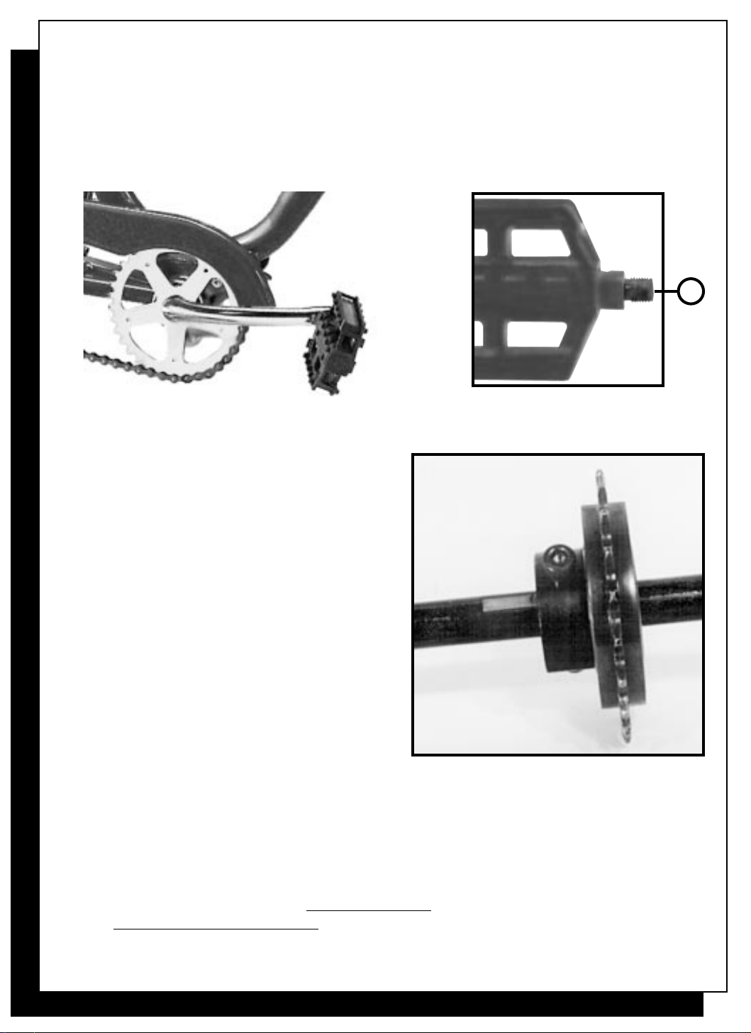
(16) 6702067 Crank one piece 6"
(14) 22240 B.B. OPC set 24 TPI
(16) 6702068 Chainring 1/2X1/8"X36T
(15) 6702295 Chainguard CP hockey stick style OPC
6702172 Chainguard CP full round style OPC
(18) 1603 Chain 1/2 X 1/8 112L
6702171 Chain 1/2 X 1/8 50L for conversion
(17) 41118 Pedal 1/2
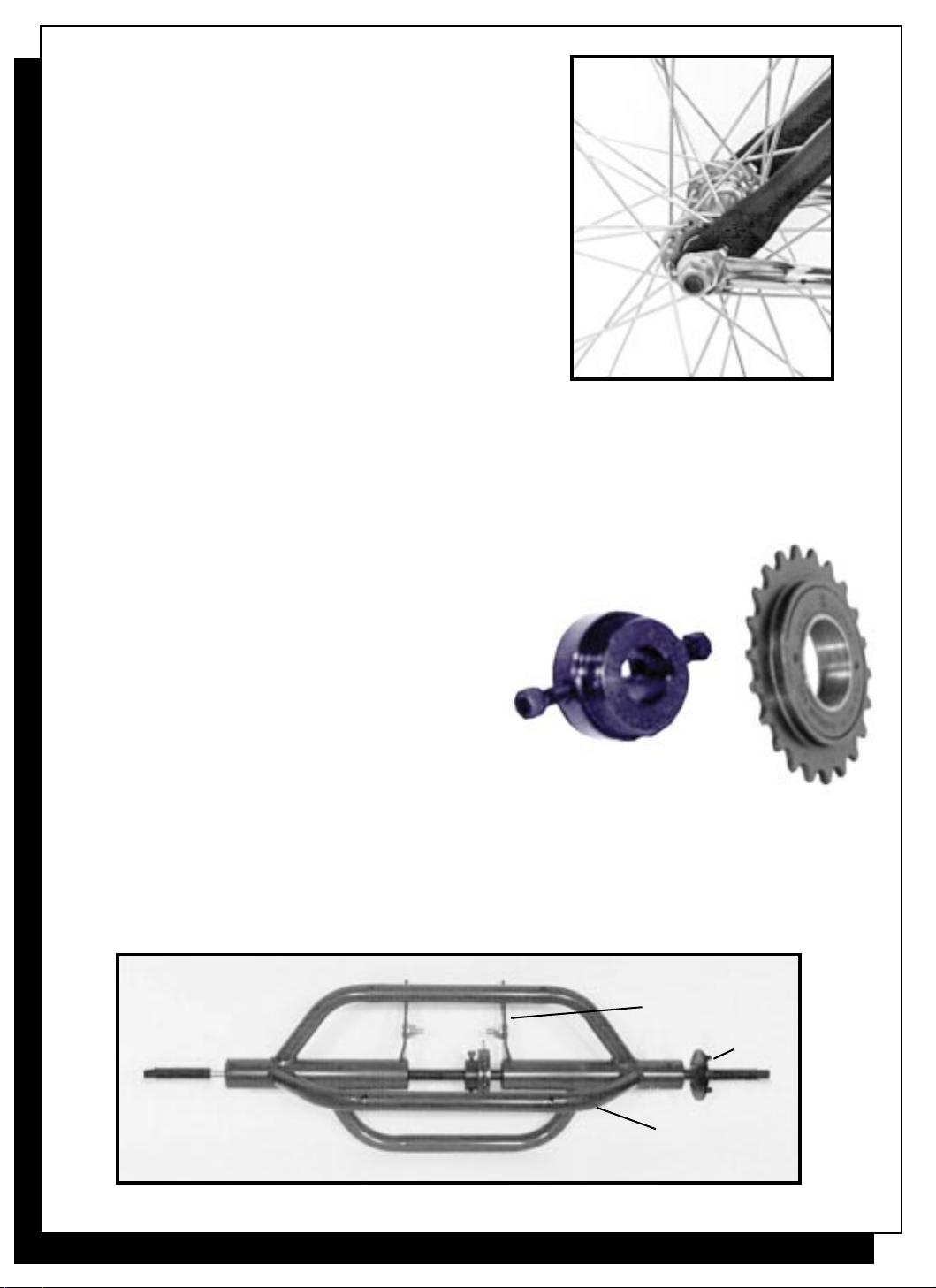
(19) 6702218 Rear unit housing Blk. for 15mm
(22) 6702210 Rear unit hardware 4pc set
(20) 6702191 Rear axle 15mm
6702192 Rear axle washer R.H.
6702193 Rear axle spacer Idler side L.H.
(24) 6702184 Bearing 15mm
(21) 6702199 FW adapter 15mm w/2 screws
(21) 6702201 Screw for adapter
(21) 18350 Freewheel 20T
6702203 Axle key for 15mm axle
6702204 Axle nut for 15mm axle
"Miami Sun"
(1) 670262 Miami Sun frame blue
(1) 670260 Miami Sun frame red
(1) 670261 Atlas frame yellow
(2) 6702291 Fork w/pivots chrome 24"
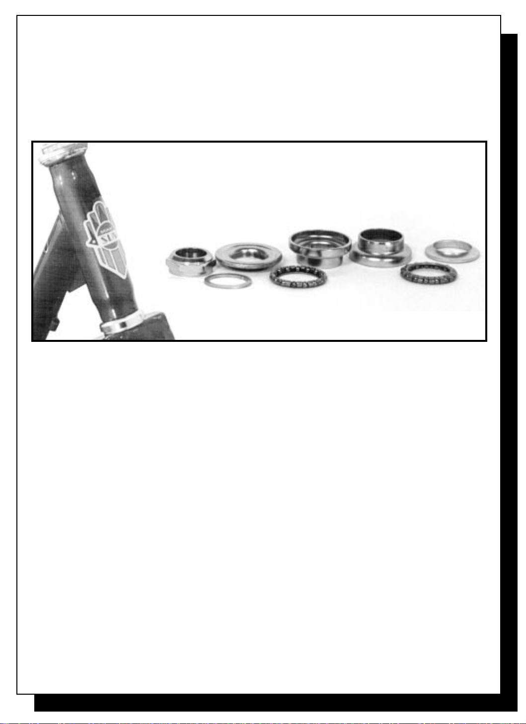
(3) 35002 Headset 30.0 X 27.0
(4) 6702290 Brake set Canti w/locking lever
6702145 Brake lever w/lock
6702146 Brake cable 890 X 760 mm Blk. Frt.
13395 Brake shoe canti white
(5) 6702155 Fender front 24" S.S. w/braces
6702158 Fender brace rear 24"
6702160 Fender rear 24" set w/braces S.S.
6702161 Fender rear 26" set w/braces
(7) 57380 Stem 6" X .875
(8) 3330 Handlebar hi-rise Wald # 870
(9) 3109 Grips 7/8 Black
(12) 6702175 Seat post chrome 28.6mm
(10) 6702130 Saddle Western USA
(10) 6702132 Saddle Western Imported
(11) 6702135 Saddle support bar
6702140 Saddle hardware western
4935 Saddle industrial trike

7
"Miami Sun"
Trike Assembly Instructions*
Step 1) Steering Head Adjustment
A. Place trike in an upright position on floor, loosen head lock nut and the adjusting cone.
B. Re-tighten adjusting cone finger-tight. Turn the fork from side to side. Fork should
turn with no rocking or free play.
C. Securely tighten head locking nut down onto washer.
Step 2) Front Wheel Alignment & Attachment
A. Place fender braces on each side of axle.
B. Check to make sure front wheel is centered in fork. If it is not, align wheel
to center of fork and retighten securely.
(Fig. 1)
* Assembly to be done by qualifed bicycle mechanic

Step 2) ContÕd
C. Make sure that safety fork washer devices
remain hooked into fork end tips.
D. “Warning:
Do not ride without safety fork washers.Ó
(Fig. 3)
8
Arms
Flange
Support Bar
Left side
Top View
Right side
Step 3) Free Wheel Rear Unit Assembly
A. Thread the free wheel adapter into the plain side
of free wheel and tighten until free wheel and
adapter are flush with each other. (Fig. 4A)
*At this time we recommend spraying the axle with
a dry Teflon lubricant for improved performance *
B. Pull unit axle halfway through unit,
install adapter with free wheel,
making sure that free wheel faces
axle flange. Now push axle all the way
through the unit.
C. Study Fig. 4B for correct positioning of components
on unit.
D. Unit is now ready to be installed on trike frame.
(Fig. 4A)
(Fig. 4B)
Note: Do not install axle key yet.

Step 4) Attaching Free Wheel Rear Unit To Frame
Installing unit to frame is a simple matter of attaching two pairs of long
and short carriage bolts. Please proceed in the following sequence:
A. Install loosely the two large carriage
bolts with their nuts and washers,
to the two holes in the end of the
trike frame stay. The heads of the
bolts are on the inside of the frame.
B. Slide the arms of assembled unit
between rear frame stays, up to
and between large carriage bolt
heads and frame slot. Finger
tighten nuts.
9
Note: Large bolts will hold seat brace in Step 10
(Fig. 5)
C. Align the first most forward holes on unit arms with rear frame slot. Attach the
two smaller carriage bolts and finger tighten. Note that the heads are outside
the frame. (Fig. 5)
D. Make sure that axle flange on unit is to the right side of unit and frame. Also
unit must be installed with support bars up, so that the basket can rest on them.
Step 5) Chain Installation &
Adjustment of F.W. Unit
A. Unsnap chain, thread chain around
chainwheel and freewheel. Reconnect
chain with two-piece connecting link.
B. Slowly pull unit towards end of trike
until chain slack is taken up.
C. Tighten the two small carriage bolts.
D. Turn chainwheel and see if chain runs
smoothly with no binding or excessive
noise. if not, loosen bolts, move unit
slightly forward. Tighten bolts and check
chain function again.
E. Make sure the chain runs straight and true with the chainwheel.
F. If chain now runs O.K. tighten all four carriage bolts securely, taking care that the
unit does not shift.
G. Now install chainguard.
(Fig. 6)

R
Step 6) Attaching Pedals
A. Each pedal axle is marked with "R" (right) or "L" (left). Install them in their correct
position. Note that the left pedal tightens by turning counter clockwise and that
the right tightens clockwise.The right side is the chain wheel side.
10
(Fig. 7)
Step 7) Axle Key Installation
A. Align axle slot with adapter slot.
Tap key into slot.
B. Check the following:
1. Axle flange is flush against unit
outer bearing.
2. Freewheel is all the way to the right
and lined up with front chainwheel
so that the chain is straight.
(Check FIG.6)
3. Now tighten set screws on adapter
securely.
(Fig.8)
Step 8) Attaching Rear Wheels
A. Both wheels are the same. The hub flanges have three holes that fit the studs on the
axle flange. Install the drive wheel first,(right side).Add axle washer on the outside
and snug down locking nut. Over-tightening
will damage the bearings.

Step 8) ContÕd
B. Now put the second wheel on left side .
This wheel is the idler. First slip on the
spacer, then the wheel, followed by a
washer and the locking nut until it touches
the bearing. Again Do Not Over Tighten.
Leave Some Play.
C. VERY IMPORTANT:It is critical for
the protection of the bearings,
that you inform your customer that the idler
wheel requires a slight amount of play in
order to prevent bearing damage.
(Fig.9)
11
Step 9) Western Seat Assembly & Installation
A. Place seat upside down. Clip
on the two seat brace clips to seat
brace. Remove two nuts from studs
in back of seat and attach brace to
seat. Tighten nuts. (Facing Forward:
Brace should be in front of studs).
B. Reposition seat post clamp so
that seat post is toward middle.
(Note fig, 10) Place seat post
on seat and tighten seat post
clamp snugly.
C. Place seat post into seat tube
of trike. Put the middle holes on
the seat brace into the two long
carriage bolts. Attach nuts.
D. Turn chainwheel and see if chain runs smoothly with no binding or excessive noise. If not,
loosen bolts, move unit slightly forward. Tighten bolts and check chain function again.
E. If chain now runs O.K. tighten all four carriage bolts securely, taking care that the unit
does not shift.
F. ÒWarning:The seat post minimum insert mark must be inside the seat tube.Ó
(Fig.10)

(Fig.12)
Step 10) Attaching
Vinyl Basket
A. With the reflector bracket on basket
facing rear,
place and center the basket onto the
unit basket support bars.
B. Align the two holes of unit basket
support bar with the holes of the basket
attaching brace. Attach nuts and bolts
and finger tighten. Repeat for other bar.
C. Tighten securely, all nuts and bolts.
D. Warning: Never put a child or pet in the basket.
(Fig.11)
12
Step 11) Attaching Stem & Handlebar
A. Loosen bolt on stem and insert stem into
head tube.
B. Insert handlebar through stem, center it
and adjust to desired angle. Tighten
handlebar binder nut securely.
C. Place handlebar and stem at right angle
to length of trike and tighten stem
expander bolt securely.
D. ÒWarning: The stem minimum
insert mark must be inside
the head tube.Ó
Step 12) Attaching Grips & Brake Lever
A. Loosen screw on brake lever attachment bracket until lever slides over right
handle of handlebar. Do not tighten screw yet.
B. Slide grips on handlebar, making sure that grips are all the way to the end of the
handlebar. Do not use any type of lubricant to install grips.
C. Slide lever back, as close as possible, to grip on handlebar. Turn lever to desired
angle and tighten securely.

(IT IS ADVISABLE THAT ALL NUTS & BOLTS BE CHECKED FOR TIGHTNESS & SECURITY)
Step 13) Attaching Reflector Kit
The white reflector is bolted to reflector bracket on fork. The red reflector is bolted to
reflector bracket on rear of basket. The wheel reflectors are installed opposite valve stems
on rims. For mag wheel the reflectors are installed on wheel tabs.
Step 15) Check Tire Inflation
Check tires for 35 lb. of air and inflate as needed.
13
(Fig. 2)
Step 14) Installation of Cantilever Brakes
A. Install brake arms by inserting the end of the spring into the middle hole on the
fork stud, tighten arm.
B. Insert the cable end-nipple into slot on brake lever.
C. Insert the cable into the cable hanger and tighten nut.
D. Set link wire end-fitting into hook side of
brake arch. Install the cable through the
link wire housing and fixing bolt.
E. Push both brake arches toward the rim,
allowing 3 mm. clearance between
brake shoes and rim. Tighten the wire
fixing nut.
F. Cut off excess cable, leaving about 25 mm. Put
protective cap on cable end and crimp with pliers.
G. ÒWarning: Removal of the front reflector bracket
could result in serious injury if the brake cable snaps and the link wire snags
the front tire.Ó

Trike Coaster Brake & 3-Speed Coaster Brake
Conversion Instruction (Optional)
Helpful Hint:
The trike CB & 3-spd. C.B.
hub units are adjusted &
aligned the same way as you
would a CB wheel on
an ordinary bike.
Note: When installing a coaster brake or 3-spd. coaster brake, you must substitute
the fixed sprocket for the free wheel.
Step 1-A)
Prepare CB hub unit by attaching
sprocket with concave side facing
outward from hub. Concave
sprocket faces in for the 3-spd. C.B.
Step 2-A)
Slide spacing washers on to axle on
brake arm side of CB unit. No washers
are used on 3-spd. C.B. hub unit.
(Fig. 13)
14

Step 3-A)
Place CB or 3-spd. C.B. hub unit
into special frame conversion slot
brackets located on top of rear
bottom frame stays, attach nuts.
( Fig.14)
Step 7-A)
Attach fixed sprocket onto rear trike
axle. See Fig. 4B (pg. 9) and step 8 (pg. 11)
You are now ready to attach unit to trike.
Step 4-A)
Attach chain (84 Links) to chainwheel
and outer CB or 3-spd. C.B. sprocket
and connect connecting link.
Step 5-A)
Pull hub towards rear to remove slack in
chain, align unit at a right angle to
frame, lightly tighten nuts.
Step 6-A)
Turn chainwheel and note chain
condition, chain must run smoothly with no
binding or excessive noise. If not, loosen
nuts and readjust unit. If O.K., tighten nuts
securely and attach brake strap to
bottom left stay.
Installing unit to frame is a simple matter of attaching two pairs of long & short
carriage bolts. Proceed in the following sequence:
Step 8-A) (Same as step 5)
1. Install loosely the two large carriage bolts with their nuts & washers, to the two holes in
the end of the trike frame stay. The heads of the bolts are on the inside of the frame.
2. Slide the legs of assembled unit between rear frame stays, up to and between
carriage bolt heads and frame slot. Tighten nuts.
TOWARD
FRONT
(Fig. 14)
15

Step 9-A) Chain Installation & Adjustment
1. Thread small 50 Link chain over CB or 3-spd. C.B. welded sprocket and unit
fixed sprocket. Connect the connecting link, align both sprockets, install axle
key and tighten set screw.
2. Slowly pull unit towards end of trike until chain slack is taken up.
3. Tighten the two small carriage bolts.
4. Turn chainwheel and see if chain runs smoothly with no binding or excessive noise.
If not, loosen bolts, move unit slightly forward. Tighten bolts and check chain
function again.
5. If chain now runs O.K. tighten all four carriage bolts securely, taking care that the
unit does not shift.
6. Proceed to Step 9 on Page 11.
3. Align the first most forward holes on unit legs with rear frame slot.Attach the two
smaller carriage bolts and finger tighten. Note that the heads are outside the frame.
4. Make sure that the axle flange on unit is to the right side of unit & frame.Also unit
must be installed with support bars up so that the basket can rest on them.
Note: Refer to general assembly instruction Pg. 7 through 13
(Fig. 15)
16
Table of contents
Other J&B Importers Bicycle manuals