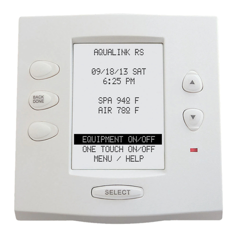
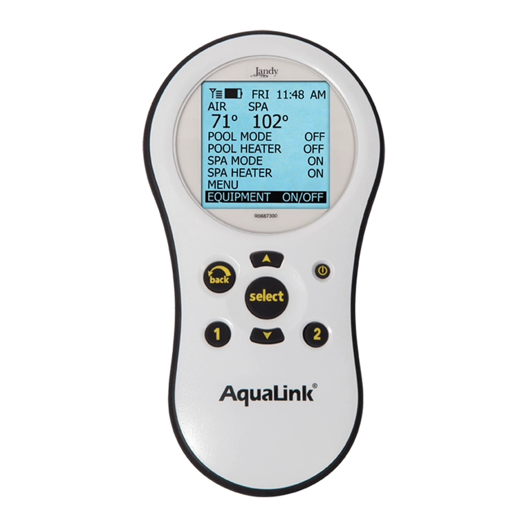
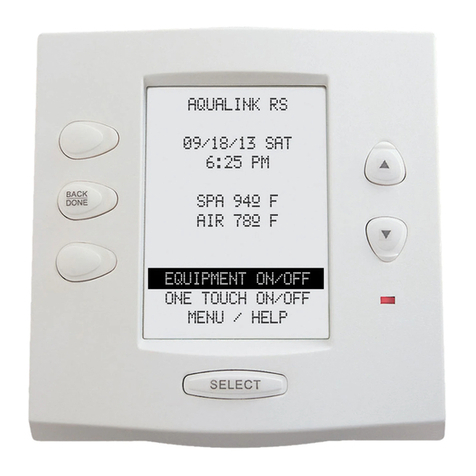
Jandy AquaLink RS6 Programming manual

Troubleshooting Data
Troubleshooting Manual
WARNING
FOR YOUR SAFETY - This product must be installed and serviced by a professional pool/
spa service technician. The procedures in this manual must be followed exactly. Failure to
follow warning notices and instructions may result in property damage, serious injury, or
death.
Pool/Spa Combination Systems
Pool/Spa Only Systems
Dual Equipment Systems
AquaLink®RS
All Button and
OneTouch™
Control Systems
6919E

Page 2

Page 3
Table of Contents
Section 1. Important Safety Instructions........ 4
Section 2. Control Panel Overview ................. 6
2.1 Indoor Control Panel ..........................................6
2.2 Controller ...........................................................6
2.3 Reset Switch ......................................................6
Section 3. Controller ....................................... 8
3.1 Diagnostics ........................................................8
3.2 Controller Troubleshooting ...............................10
3.3 Heater Operation..............................................13
Section 4. Power Center .............................. 14
4.1 Overview ..........................................................14
4.2 Power Center Troubleshooting.........................15
4.3 Main Power Center PCB ..................................16
Section 5. Auxiliary Power Center ................ 18
5.1 Overview ..........................................................18
5.2 DIP Switches ....................................................19
5.3 Water Temperature Sensor ..............................21
5.4 3 HP Relay .......................................................23
5.5 Two Speed Relay .............................................25
5.6 Light Dimming Relay ........................................27
Section 6. Jandy Valve Actuator ................... 29
6.1 Operation..........................................................29
Section 7. Troubleshooting ........................... 31
7.1 Quick Check List ..............................................31
7.2 Controller Inoperable, Display Blank ................33
7.3 All Lights Lit on Controller ................................34
7.4 Some Controller Buttons Do Not Operate ........35
7.5 Three Amp Fuse Keeps Failing ........................36
7.6 Heater Doesn't Fire ..........................................37
Section 8. Flow Charts................................... 38
8.1 OneTouch Menu Flow Chart.............................38
8.2 All Button Menu Flow Chart..............................39
8.3 All Button Cancel Flow Chart ...........................40
Section 9. Wiring Diagrams........................... 41
9.1 AquaLink RS Pool/Spa Combination and Pool/
Spa Only...........................................................41
9.2 AquaLink RS Dual Equipment..........................42
9.3 AquaLink RS Auxiliary Power Center ...............43
Section 10. Power Center Bezel...................... 44

Page 4
Section 1. Important Safety Instructions
READ AND FOLLOW ALL INSTRUCTIONS
Lire la notice technique.
All electrical work must be performed by a licensed electrician and conform to all national, state, and local codes.
When installing and using this electrical equipment, basic safety precautions should always be followed, including the
following:
WARNING
Prolonged immersion in hot water may induce hyperthermia. Hyperthermia occurs when the internal temperature
of the body reaches a level several degrees above the normal body temperature of 98.6° F. The symptoms of
hyperthermia include dizziness, fainting, drowsiness, lethargy, and an increase in the internal temperature of the
body. The effects of hyperthermia include: 1) unawareness of impending danger; 2) failure to perceive heat; 3)
failure to recognize the need to exit spa; 4) physical inability to exit spa; 5) fetal damage in pregnant women; 6)
unconsciousness resulting in a danger of drowning.
DANGER
To reduce the risk of injury, do not remove the suction fittings of your spa or hot tub. Never operate a spa or hot
tub if the suction fittings are broken or missing. Never replace a suction fitting with one rated less than the flow rate
marked on the equipment assembly.
WARNING
To Reduce the Risk of Injury -
a) The water in a spa should never exceed 104°F (40°C). Water temperatures between 100°F (38°C) and 104°F
(40°C) are considered safe for a healthy adult. Lower water temperatures are recommended for young children
and when spa use exceeds 10 minutes.
b) Since excessive water temperatures have a high potential for causing fetal damage during the early months of
pregnancy, pregnant or possibly pregnant women should limit spa water temperatures to 100°F (38°C).
c) Before entering a spa or hot tub, the user should measure the water temperature with an accurate
thermometer since the tolerance of water temperature-regulating devices varies.
d) The use of alcohol, drugs, or medication before or during spa or hot tub use may lead to unconsciousness with
the possibility of drowning.
e) Obese persons and persons with a history of heart disease, low or high blood pressure, circulatory system
problems, or diabetes should consult a physician before using a spa.
f) Persons using medication should consult a physician before using a spa or hot tub since some medication
may induce drowsiness while other medication may affect heart rate, blood pressure, and circulation.
WARNING
Risk of electric shock - Install the power center at least five (5) feet (152.4cm) from the inside wall of the pool
and/or hot tub using non-metallic plumbing. Canadian installations must be at least three (3) meters from the water.
Children should not use spas or hot tubs without adult supervision.
Do not use spas or hot tubs unless all suction guards are installed to prevent body and hair entrapment.
People using medications and/or having an adverse medical history should consult a physician before using a spa
or hot tub.
AVERTISSEMENT
Danger d'electrocution - Les installations canadiennes doivent se trouver à au moins trois (3) mètres de l’eau.
Ne pas laisser les enfants utiliser une cuve de relaxation sans surveillance.
Pour éviter que les cheveux ou une partie du corps puissent être aspirés, ne pas utiliser une cuve de relaxation si
les grilles de prise d'aspiration ne sont pas toutes en place.
Les personnes qui prennent des médicaments ou ont des problèmes de santé devraient consulter un médecin
avant d’utiliser une cuve de relaxation.

Page 5
CAUTION
A ground-fault circuit-interrupter must be provided if this device is used to control underwater lighting fixtures. The
conductors on the load side of the ground-fault circuit-interrupter shall not occupy conduit, boxes, or enclosures
containing other conductors unless the additional conductors are also protected by a ground-fault circuit-
interrupter. Refer to local codes for complete details.
CAUTION
A terminal bar marked "GROUND" is provided within the power center. To reduce the risk of electrical shock,
connect this terminal bar to the grounding terminal of your electric service or supply panel with a continuous
copper conductor having green insulation and one that is equivalent in size to the circuit conductors supplying this
equipment, but no smaller than no. 12 AWG (3.3mm). In addition, a second wire connector should be bonded with
a no. 8 AWG (4.115mm) copper wire to any metal ladders, water pipes, or other metal within five (5) feet (1.52m) of
the tub.
SAVE THESE INSTRUCTIONS
WARNING
People with infectious diseases should not use a spa or hot tub.
To avoid injury, exercise care when entering or exiting the spa or hot tub.
Do not use drugs or alcohol before or during the use of a spa or hot tub to avoid unconsciousness and possible
drowning.
Pregnant or possibly pregnant women should consult a physician before using a spa or hot tub.
Water temperature in excess of 100°F/38°C may be injurious to your health.
Before entering a spa or hot tub measure the water temperature with an accurate thermometer.
Do not use a spa or hot tub immediately following strenuous exercise.
Prolonged immersion in a spa or hot tub may be injurious to your health.
Do not permit any electric appliance (such as a light, telephone, radio, or television) within 5 feet (1.5 m) of a spa
or hot tub.
The use of alcohol, drugs or medication can greatly increase the risk of fatal hyperthermia in hot tubs and spas.
Water temperature in excess of 100°F/38°C may be hazardous to your health.
Attention installer: Install to provide drainage of compartment for electrical components.
WARNING
To avoid injury ensure that you use this control system to control only packaged pool/spa heaters which have built-
in operating and high limit controls to limit water temperature for pool/spa applications. This device should not be
relied upon as a safety limit control.
AVERTISSEMENT
Les personnes atteintes de maladies infectieuses ne devraient pas utiliser une cuve de relaxation.
Pour éviter des blessures, user de prudence en entrant dans une cuve de relaxation et en sortant.
Pour éviter l’évanouissement et la noyade éventuelle, ne prendre ni drougue ni alcool avant d’utiliser une cuve de
relaxation ni quand on s’y trouve.
Les femmes enceintes, que leur grossesse soit confirmée ou non, devraient consulter un médecin avant d’utiliser
une cuve de relaxation.
Il peut être dangereux pour la santé de se plonger dans de l’eau à plus de 38°C/100°F.
Avant d’utiliser une cuve de relaxation mesurer la témperature de l’eau à l’aide d’un thermomètre précis.
Ne pas utiliser une cuve de relaxation immédiatement après un exercice fatigant.
L’utilisation prolongée d’une cuve de relaxation peut être dangereuse pur la santé.
Ne pas placer d'appareil électrique (luminaire, téléphone, radio, téléviseur, etc) à moins de 1.5m de cette cuve de
relaxation.
La consommation d’alcool ou de drogue augmente considérablement les risques d’hyperthermie mortelle dans une
cuve de relaxation.
Il peut etrê dangereux pour la santé de se plonger dans de l’eau à plus de 38°C/100°F.

Page 6
Section 2. Control Panel Overview
2.1 Indoor Control Panel
The indoor control panel serves as a means of turning equipment on and off, entering programs to run equipment
automatically at selected times, and displaying what is going on in the rest of the system. Programs (and other
information entered through the controller) are stored in a memory chip on the power center board, even during a
power interruption (however long).
2.2 Controller
The power center supplies the controller 10 VDC via the two (2) outside wires (red and green) of the four (4)
conductor cables. If the voltage drops below 8 VDC, the display will flicker on and off. The two (2) inner wires
(yellow and black) provide the two-way communication link between the controller and the power center. They
communicate via serial communication, using signals like the standard "RS-485".
If either of the communication wires (inner pair) is broken or misconnected, but the power supply wires (the outer
pair) are connected properly, the controller will stop responding. It may show a steady screen of information, and stop
responding to its buttons. If power is then interrupted, the controller will lock up. The way it locks up will depend on
the type of controller.
1. Locked-up All Button. All LEDs will be on and the text will resemble the following: "6700 REV C".
2. Locked-up OneTouch. The screen will be covered with dots, with a line of text that resembles the following:
"Firmware Rev XXX".
2.3 Reset Switch
1. All Button Controller. Pressing the reset switch, located on the left side, will momentarily display the software
part numbers and revision letters for both the controller's micro controller chip and the power center's firmware
chip. The reset switch also resets the micro controller, but does not remove any programming, AUX labels, etc.
2. OneTouch Controller. The reset switch can be used to show the revision code for the firmware for both the
controller's micro controller chip and the power center's firmware chip.

Page 7
Page Up/
OneTouch 1
Back/
OneTouch 2
Page Down/
OneTouch 3
Controller 1
Controller 2
Controller 3
Controller 4
W 2
W 1 W 2
W 1
W 2
W 1 W 2
W 1
Jumper Settings for
Multiple Controllers
Cancel Delay
Button*
Reset
Switch*
Highlight Bar
Moves High-
lighted Bar
Up or Down
Selects
Highlighted
Items
Figure 1. All Button Controller (Front View)
Figure 2. All Button Controller (Back View)
Figure 3. OneTouch Controller (Front View)
Figure 4. OneTouch Controller (Face Plate Removed)
W 2 W 2
W 2 W 2
W 1 W 1
W 1 W 1
Controller 1
Controller 2
Controller 3
Controller 4
Jumper Settings for
Multiple Controllers
Jumpers for
Multiple Controllers
Display Module
Micro Controller
Green
Yellow
Black
Red
*Items Hidden by Cover

Page 8
Section 3. Controller
3.1 Diagnostics
The AquaLink system has an internal self-checking process, which can display its current status on the indoor control
panel. Use the following steps to get to this "diagnostics" information:
1. All Button: Use the buttons along the lower left side of the controller.
a. Press MENU, BACK, and BACK again until SYSTEM SETUP displays on the screen.
b. Press ENTER (*), BACK, and BACK again until DIAGNOSTICS displays on the screen.
c. Press ENTER, and read the information that is presented in order.
NOTE To step through the information faster, press an arrow key (for example, Up). If you make a mistake, select CANCEL
before selecting ENTER again. When done, the controller will return automatically to its normal operating cycle.
2. OneTouch: From the main OneTouch screen, use the Up or Down arrow button.
a. Highlight MENU (press Select).
b. Highlight HELP (press Select), highlight DIAGNOSTICS (press Select).
c. Press BACK when done.
Information displayed includes identification of the exact model number (shown as a four (4) digit firmware number)
and firmware revision letter, and the status of the battery, temperature sensors, and other devices that are currently
working on-line (communicating with the power center). If an LX or LXi heater is on-line, information about its error
condition (if any) will also be shown here.

Page 9
Table 1. Diagnostics Table
Possible Online
Devices
As Shown in
Diagnostics While
Online
Possible Unit
Numbers
Unit Order*
Important?
Earliest PPD
Revision Usable
All Button CONTROL PANEL 1,2,3,4 No* C
AquaLink PC CONTROL PANEL 4 4 Yes** C
OneTouch ONETOUCH 1,2,3,4 No I
Wireless
OneTouch***
ONETOUCH 1,2,3,4 No I
Serial Adapter SERIAL ADAPTR 1,2, No I
PHASTLink Serial
Adapter
SERIAL ADAPTR 1,2 No I
SpaLink®RS SPALINK 1,2,3 No G
Dual Spa Side Switch SPA SW BOARD ---- ---- C
Tele-Link®TELELINK 1 1 ---- C
Auxiliary Power
Center
REMOTE PWRCNTR 1,2,3 Yes
LX Heater LX HTR 1,2 Yes H
AquaPure®
Chlorinator
AquaPure 1 ---- I
AquaPalm™AQUAPALM 1 ---- MMM
RS InterLink ---- ---- N
LXi Heater LXi HTR 1,2 Yes N
* Unit order. Yes means that the unit number must be set correctly or the device will not work properly. The unit number is set by
slide-on jumpers, a DIP switch, or a wire, depending on the type of device.
**If an AquaLink PC is online, there must NOT be an All Button or OneTouch jumpered, as in number 4.
***Wireless OneTouch is shown as any other OneTouch. Its jumpers must not match the jumpers in any other OneTouch.

Page 10
3.2 Controller Troubleshooting
3.2.1 Display Is Not Illuminated
Check the voltage between the red and green wires at the red terminal bar (terminals 1 and 4). If the voltage is
between 8 and 10 VDC, check the polarity. The red wire is positive (+) and the green wire is negative (-). If the
voltage and polarity are correct, replace the control panel. If the voltage is less than 8 VDC, go to the power center.
1. At the power center, check the voltage between the red and green wires at the red terminal bar (terminals 1 and 4).
See Figure 5. If the voltage is between 8 and 10 VDC and the polarity is correct, but there is less than 7 VDC at
the indoor control, check the wires for the following:
a. Broken or shorted red or green wires.
b. Wire size. The minimum gauge for one control no more than 300 feet away from the power center is 22 AWG.
To ensure a lower drop in current, use larger wire (16 to 20 AWG)
2. If the voltage is less than 7 VDC, check the following:
a. Transformer secondary wires (two yellows). See Figure 6. If the voltage is less than 22 VAC, check the
incoming (primary power) to the system.
b. If the power to the transformer primary is less than 105 VAC, contact the power supply company.
c. If the voltage to the transformer primary is above 105 VAC, but the transformer secondary is less than 22
VAC, replace the transformer.
d. If the secondary voltage is 24 to 28 VAC, turn off the power.
e. Remove the fuse from its holder and do a continuity test. If there is no continuity, unplug all the Jandy Valve
Actuators (JVAs), replace the fuse (3.15 amp), and turn on the power. If the fuse blows with all JVAs unplugged,
the circuit board is damaged and needs to be replaced. If the fuse does not blow, plug a JVA cord into the Intake
JVA Socket. Test the JVA by switching to SPA. If the fuse holds, remove the tested JVA and plug the next JVA
into the Intake JVA Socket. Continue until all JVAs have been tested or the fuse blows.

Page 11
S1
S2
654321
10987654321
4321 4321
RESET
SERVICE
TIME OUT
FILTERPUMP
AUX 1
AUX 2
AUX 3
AUX 4
AUX 5
AUX 6
AUX 7
RS6 & RS8 ONLY
RS8 ONLY
HEATER SOLAR
POOL MODE
SPAMODE
SPADRAIN
SPAFILL
AUTO
Red
Wire
Green
Wire
Figure 5. Checking Voltage at Red Terminal Bar
Figure 6. Transformer Primary and Secondary Voltages
Check for broken or loose
wires on terminals 1 and 4
(red and green) of the red
4-pin terminal bar.
Fuse
3.15 amp
24 – 28 VAC
Yellow wires
105 – 130 VAC
Transformer
Secondary Primary

Page 12
3.2.2 Control Not Communicating with Power Center PCB
The following conditions indicate that the control is not communicating with the power center PCB:
1. All Button Control: All the circuit LEDs are illuminated and the display is locked on a part number and revision
letter.
2. OneTouch Control: The screen is covered with dots and displays a firmware version number.
Communication problems can be caused by the following:
1. Broken communication wire(s). These wires are connected to the red terminal bar at terminals two (2) and three
(3 ) (yellow and black). See Figure 7.
2. The microprocessor was hit by a power surge. Turn off all power to the system. (If the PCB is prior to Revision N,
disconnect the nine (9) volt battery.) Wait two (2) minutes and then turn the power on. If this frees up the system,
you will need to reset the time and date, except with a Revision N board. Programming will not be lost. It is
advisable to install a Surge Protection Kit.
Figure 7. Checking Communication Problems between Control and Power Center PCB
S1
S2
654321
10987654321
4321 4321
RESET
SERVICE
TIME OUT
FILTER PUMP
AUX 1
AUX 2
AUX 3
AUX 4
AUX 5
AUX 6
AUX 7
RS6 & RS8 ONLY
RS8 ONLY
HEATER SOLAR
POOL MODE
SPAMODE
SPADRAIN
SPAFILL
AUTO
Check for broken
yellow or black wires.
Check for broken
yellow or black wires.

Page 13
3.3 Heater Operation
The pool and spa heater LED and the solar LED are two-color LEDs. Green indicates the heater is enabled but not on.
Red indicates the signal to the heater relay is being sent. A heater or solar LED will remain green for the following
reasons:
1. Thermostat setting has been reached.
2. Thermostat setting is below the water temperature.
3. Water temperature sensor has failed.
4. Other body of water is circulating (i.e., pool heater is enabled but spa is circulating).
To eliminate the control system as the cause of the heating problem, insert both wires to the heater into the same
terminal of the green terminal bar, as shown in Figure 8. If the heater does not operate, the problem is in the wires or
the heater, not the control system. Reinsert wires into the correct terminals after the test.
S1
S2
654321
10987654321
4321 4321
RESET
SERVICE
TIME OUT
FILTER PUMP
AUX 1
AUX 2
AUX 3
AUX 4
AUX 5
AUX 6
AUX 7
RS6 & RS8 ONLY
RS8 ONLY
HEATER SOLAR
POOL MODE
SPA MODE
SPA DRAIN
SPA FILL
AUTO
To Heater
Figure 8. Connecting Both Heater Wires to the Same Terminal for Testing

Page 14
Section 4. Power Center
4.1 Overview
The power center PCB is the true brain of the system. The micro-controller on the PCB is constantly sending signals
through the communication wires to the control panel and polling the system to determine which circuits should be on
and which should be off.
4.1.1 Driver Chips
The driver chips can be thought of as a series of small relays. When one of the driver chips receives a signal, it closes
a contact which passes 24 to 32 VDC to the appropriate relay coil socket, in this case AUX 1. Each relay driver chip
activates a specific set of relay coil sockets (see the chart below). If a driver chip fails, it is usually caused by either
shorted relay coil wires, a shorted relay coil, or a relay not designed for the 24 VDC coil voltage (i.e., 24 VAC rather
than 24 VDC). The relay coil provides resistance (approximately 300 Ohms); if there is no resistance, the driver chip
circuit will be damaged.
4.1.2 Reset Button
Pressing the reset button, located in the upper left hand corner of the power center bezel, resets the power center
micro-controller. This also changes the time and date to the default settings for PCBs prior to Rev N. Pressing this
button will not remove any programming, AUX labels, etc.
4.1.3 EEPROM
All programming, labeling, temperature settings, etc., are stored within an EEPROM (Electronically Erasable Pro-
grammable Read Only Memory) chip. This chip is located on the PCB and will retain all settings indefinitely, even if
power is lost for an extended period. If the Power Center PCB is prior to Rev N, a 9-volt battery will keep the clock
running during power outages.
4.1.4 Battery
If the power is off for more than 34 hours, the battery will drain below 6.3 volts. This is insufficent to keep the clock
running, therefore, the date and time will be lost. If the PCB is Rev N or newer, a three (3) volt lithium battery will
keep the clock running during a power outage. If the line power is off for more than three (3) years, this battery may
drain to the point where it will no longer keep the clock running. Even if the battery is dead, the user inputs (Pro-
grams, Labels, Temperature Settings, etc.) will never be lost.

Page 15
4.2 Power Center Troubleshooting
4.2.1 Loss of Power
Check the power center transformer for the proper voltage.
1. Disconnect the transformer from the power center PCB. Check the voltage on the secondary transformer (the
two (2) outside yellow wires). The two (2) outside wires provide the 24 to 28 VAC to the PCB.
2. If there is less than 22 VAC at the secondary wires, check the voltage at the primary (black and white) wires for
105 to 130 VAC. If there is no voltage on the primary, check the supply source (the circuit breaker).
3. If there is 105 to 130 VAC on the primary and no voltage on the secondary, replace the transformer. Note: the
transformer and/or its fuse can be damaged by a short circuit. Water in the JVA can cause a short. A cut or spliced
JVA cord can cause a short. A damaged chip on the PCB (usually a driver chip) can cause a short.
Figure 9. Transformer Voltage Test
The two (2) outside wires provide the 24 to 28 VAC to
the PCB. The center wire is a ground. There is a four
(4) amp fuse between the secondary leads hidden
behind the transformer secondary cover.
Power Center
Transformer
4 Amp
Fuse
Secondary 24
to 28 VAC
Primary 105
to 130 VAC

Page 16
4.3 Main Power Center PCB
4.3.1 PCB Circuit Layout
1. JVA Relays (K2 - K5)
2. Low Voltage Heater Relay
3. 3.15 amp fuse. Fuse will blow to protect the transformer when there is a short circuit in the JVA(s) or the circuit
board driver chip is damaged.
4. CPU Board
5. U2 Communication Chip. This chip will be damaged if a lightning strike hits the four (4) conductor wires. It will
turn brown when damaged. This chip is mounted on the PCB board and is located underneath the top edge of the
CPU board.
6. Sprinkler Module Connector
7. Battery (3 Volt Lithium)
8. Spare Auxiliary. Operates with pool/spa combo units only. With firmware prior to Rev. I this socket is on when
the filter pump is on and the system is in pool mode. It turns off when the spa is activated. With Rev. I or newer,
turning on dip switch 6 will reverse the operation of this socket (i.e. on in spa mode and off in pool mode).
Figure 10. Main Power Center PCB, Back View
Figure 11. Main Power Center PCB, Front View
264
5
17
3
S1
S2
654321
10987654321
4321 4321
RESET
SERVICE
TIME OUT
FILTER PUMP
AUX 1
AUX 2
AUX 3
AUX 4
AUX 5
AUX 6
AUX 7
RS6 & RS8 ONLY
RS8 ONLY
HEATER SOLAR
POOL MODE
SPAMODE
SPADRAIN
SPAFILL
AUTO
8

Page 17
4.3.2 PCB Voltages
1. From Power Center to Controller, between terminals one (1) and four (4) of the two (2) red terminal blocks = 8 to
10 VDC.
2. To JVA 2444 = 24 to 28 VAC*.
3. To Relay Coils = 24 to 32 VDC*.
4. Transformer Primary = 105 to 130 VAC.
5. Transformer Secondary = 24 to 28 VAC.
* Never measure voltage at the socket.
S1
S2
654321
10987654321
4321 4321
RESET
SERVICE
TIME OUT
FILTER PUMP
AUX 1
AUX 2
AUX 3
AUX 4
AUX 5
AUX 6
AUX 7
RS6 & RS8 ONLY
RS8 ONLY
HEATER SOLAR
POOL MODE
SPA MODE
SPA DRAIN
SPA FILL
AUTO
Connection to
Controller
10 VDC
Spa
Side
Switch
Sensors
and
Heater
Relay Sockets
24 VDC
Relay Sockets
24 VDC
JVA Sockets
24 VAC
Filter Pump
Aux 1
Aux 3
Aux 2
Aux 4
Aux 5
Aux 6
Aux 7
Intake
Return
Cleaner
Solar
Solar Pump
Elect. Htr.
Spare
Auto Light
Valves Light
Transformer
Connection
24 VAC
Figure 12. PCB Voltages

Page 18
Section 5. Auxiliary Power Center
5.1 Overview
An auxiliary power center provides control for systems that need to run more relays (and/or JVAs) than can be
handled by the main power center. The main one is still the central "brain" of the system; it sends control signals to
the auxiliary power center PCB through the 4-wire bus (red connector). Those control signals tell the auxiliary power
center which of its relays to turn on, and it provides the power for them. There are no temperature sensors or DIP
switches in the auxiliary power center, and it has no battery (as it depends on the time keeping that’s done by the main
power center).
5.1.1 Jumpers
Jumpers “W1” and “W2”: these are slide-on jumpers on the back side of the auxiliary power center board. They
identify the board and must be set correctly, or the board will not respond properly to commands from the main power
center PCB. (See below for jumper settings.)
5.1.2 Driver Chip
A driver chip (U6) drives the relays, just like the similar chips on the main power center. It is in a socket, to simplify
replacement in case of damage.
5.1.3 Switch
The left-most (bottom) switch on the auxiliary power center bezel works just like the one on the main power center,
changing from AUTO to SERVICE to TIME OUT (3 hour) and back to AUTO.
5.1.4 JVA Sockets
The (4) JVA sockets are driven together with the first (4) auxiliary relays here (they are not independent). Dimming:
use the second four (4) auxiliary sockets (B5 – B8) for light dimming relays, rather than the first four. (See section on
Light Dimming, later in this manual.)
Figure 13. Auxiliary Power Center

Page 19
5.2 DIP Switches
All DIP switches are located on the left side of the power center bezel. To change a setting, turn off the power and
move the approprate switch from left (OFF) to right (ON).
S1
S2
654321
10987654321
4321 4321
RESET
SERVICE
TIME OUT
FILTER PUMP
AUX 1
AUX 2
AUX 3
AUX 4
AUX 5
AUX 6
AUX 7
RS6 & RS8 ONLY
RS8 ONLY
HEATER SOLAR
POOL MODE
SPA MODE
SPA DRAIN
SPA FILL
AUTO
OFF ON
Figure 14. Dip Switches
Table 2. Pool and Spa Combination Controls
S1 DIP Switch # OFF ON
1Aux. 1 = Any equipment Aux. 1 = Pool cleaner
2Aux. 2 = Any equipment Aux. 2 = Low speed for a two (2) speed filter
pump. Filter pump circuit becomes high speed.
3Aux. 3 = Any equipment Aux. 3 = Spa spillover effect. Combo controls
only.
4Heater cool down operates. Heater cool down disabled.
5Normal operation Factory adjustment. When this switch is on, tem-
perature delays are eliminated and solar tempera-
ture is displayed. Do not leave this switch in the
ON position.
6Spare Aux has power when filter pump is in
Pool Mode, goes off when in Spa Mode.
Spare Aux has power when filter pump circuit is
in Spa Mode, goes off when in Pool Mode.
7Spare No change on Combo or Only controls (see Dual
Equipment DIP Switch settings).
8After thermostat setting has been reached, the
heater will remain off for three (3) minutes.
After thermostat setting has been reached, the
heater will remain off for five (5) minutes.
S2 DIP SWITCH OFF ON
1The AquaLink RS will be able to control
a Solar Heating system (If a solar sensor
is connected to the solar sensor input).
The AquaLink RS will be able to control a
Heat Pump. (The AquaLink RS will not be
able to control a Solar Heating system.)
2 NOT USED
3 NOT USED
4 NOT USED

Page 20
Table 3. Pool or Spa Only Controls
Table 4. Dual Equipment Controls
DIP Switch # OFF ON
1Aux. 1 = Any equipment Aux. 1 = Pool cleaner
2Aux. 2 = Any equipment Aux. 2 = Low speed for a two speed filter pump.
Filter pump circuit becomes high speed.
3Aux. 3 = Any equipment Aux. 3 = Spa spillover effect. Combo controls
only.
4Heater cool down operates. Heater cool down disabled.
5Normal operation Factory adjustment. When this switch is on, tem-
perature delays are eliminated and solar tempera-
ture is displayed. Do not leave this switch in the
ON position.
6Spare No change.
7Spare No change.
8After thermostat setting has been reached, the
heater will remain off for three (3) minutes.
After thermostat setting has been reached, the
heater will remain off for five (5) minutes.
DIP Switch # OFF ON
1Aux. 1 = Any equipment Aux. 1 = Pool cleaner
2Aux. 2 = Any equipment Aux. 2 = Low speed for a two speed filter pump.
Filter pump circuit becomes high speed.
3Spare No change.
4Heater cool down operates. Heater cool down disabled.
5Normal operation Factory adjustment. When this switch is on, tem-
perature delays are eliminated and solar tempera-
ture is displayed. Do not leave this switch in the
ON position.
6Separate pool and spa heaters Sharing one heater
7No solar system installed. Air temperature
displayed.
Changes air sensor to solar sensor. Air tempera-
ture no longer displayed. AquaLink RS Adjust-
able Freeze Kit must be added fro freeze protec-
tion.
8After thermostat setting has been reached, the
heater will remain off for three (3) minutes.
After thermostat setting has been reached, the
heater will remain off for five (5) minutes.
Other manuals for AquaLink RS6
1
This manual suits for next models
1
Table of contents
Other Jandy Control System manuals
Popular Control System manuals by other brands

Redback
Redback A 6500 operating manual

SALUPO
SALUPO IMPEDANCE 1 SQ701. Series Instruction and installation manual

Pentair
Pentair INTELLICENTER installation guide

Cypress
Cypress CIR-03 Operation manual

Fagor
Fagor 8070 BL Programming manual

Zap
Zap JACKSHAFT MOTOR-CONTROL SYSTEM 815-RL installation instructions

Urbaco
Urbaco G6EVO Installation and operation manual

Progressive Industries
Progressive Industries EMS-LCHW30 Operating and installation guide

Comat Releco
Comat Releco CMS-10R Series user manual

SEA
SEA STORM manual

Schake
Schake 413 300V installation guide

Lutron Electronics
Lutron Electronics AuroRa installation guide