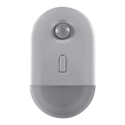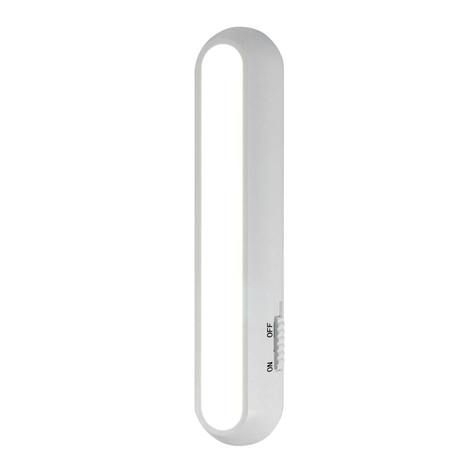
Direct-Wire LED Light Fixture
Before installing, read all safety instructions listed at the end of this manual.
Consult a local licensed electrician or electrical contractor if you are not sure about installing the
direct-wire fixture yourself. Save these instructions for later use.
Step 1: Turn power OFF. Ensure that electricity is TURNED OFF at the main circuit breaker or fuse box.
DO NOT ATTEMPT TO INSTALL THE FIXTURE WITH POWER ON
Step 2: Select mounting location. Choose a location that is clean, dry and capable of supporting the
fixture. NOTE: The ideal mounting orientation for the light fixture is near the front lip of your
cabinets as shown in the illustration (see Figure 1) — this provides the best light distribution
across a countertop.
Step 3: Remove lens/diuser. Remove the lens/diuser by lightly pulling the rear edge towards you
and upwards.
Step 4: Remove housing from base. Using a #1 Phillips-head screwdriver (not included), remove the
screws securing the housing to the base. Firmly push forward on the bottom front of the housing to
unlatch it from the catch points — retrieve the hardware kit inside.
Step 5: Remove knock-out tab. Choose a knock-out location from those provided on
the fixture and carefully remove it using a screwdriver. NOTE: When choosing a
knock-out, consider which part of the fixture will be closest to power.
Step 6: Strain relief. Remove the nut and lock washer from the strain relief and insert
the threaded end into the newly created knock-out hole on the fixture. Reattach the
lock washer and nut and secure the strain relief in place — tighten with pliers if
needed (not included).
Step 7: Mark screw locations. Hold the base in place and mark the location for each
screw with a pencil using the keyholes for guidance (see Figure 2).
Step 8: Drill pilot holes. Create pilot holes on each pencil marking using a drill and a
1/16in. drill bit for softwoods and a 3/32in. drill bit for hardwoods.
Step 9: Insert screws. Use a #1 Phillips-head screwdriver to drive each of the included screws into the pilot holes,
leaving the heads protruding approximately 1/8in. from the surface (see Figure 3).
Step 10: Mount fixture. Align the keyholes on the fixture with the two installed screws and slide it into place (see
Figure 4) — tighten screws as needed.
Step 11: Hang cover on base. For ease of installation, hook the cover onto the mounted base using the built-in flanges.
Step 12: Insert power cable into fixture. Install the armored house cable to meet electrical codes. Carefully thread the
cable through the strain relief and into the fixture, tightening the two screws on the strain relief to secure it
into place.
Step 13: Hot AC wires (black). Connect the hot (black) AC supply wire to the hot (black) wire
of the fixture. Secure the connection with the quick connects (see Figure 5). Gently pull
the wires to check for tightness.
Step 14: Neutral AC wires (white). Connect the neutral (white) AC supply wire to the neutral
(white) wire of the fixture. Secure the connection with the quick connects (see Figure 5).
Gently pull the wires to check for tightness.
Step 15: Grounding wires (green/copper). Connect the ground (green/copper) AC supply wire
to the ground (green/copper) wire of the fixture. Secure the connection with the quick
connects (see Figure 5). Gently pull the wires to check for tightness.
Step 16: Arrange wires and reattach housing. Ensure that no bare wires are exposed
after making the electrical connections. Arrange the connected wires inside the
fixture without “pinching” any and reattach the housing.
Step 17: Reattach lens/diuser. Reattach the lens/diuser to the housing by gently
pushing it back into place.
Step 18: Restore power. With everything properly installed, restore power at the main
circuit breaker or fuse box.
x 2 x 3
x 1
INCLUDED INSTALLATION
ACCESSORIES
Figure 2
1/16in. (1.5mm) from the end
CABINET
COUNTER TOP
WALL
Figure 1
WARNING
RISK OF ELECTRIC SHOCK
- DO NOT USE IN WET LOCATIONS.
- USE INDOORS ONLY.
- TURN POWER OFF BEFORE SERVICING — SEE INSTRUCTIONS.
- PROPERLY GROUND FIXTURE.
- ENSURE THAT NO BARE WIRES ARE EXPOSED OUTSIDE THE ELECTRICAL
CONNECTIONS.
RISK OF INJURY
- SOME METAL PARTS IN THE FIXTURE MAY HAVE SHARP EDGES. TO PREVENT
CUTS AND SCRAPES, WEAR GLOVES WHEN HANDLING THE PARTS.
- DO NOT OPERATE THE UNIT WITH A MISSING OR DAMAGED LENS.
- DO NOT INSTALL ON WALLS OR VERTICAL SURFACES.
- ACCOUNT FOR SMALL PARTS AND DESTROY PACKING MATERIAL, AS THESE
MAY BE HAZARDOUS TO CHILDREN.
RISK OF FIRE
- MINIMUM 90º C SUPPLY CONDUCTORS.
- NOT INTENDED FOR ILLUMINATION OF AQUARIUMS.
- NOT INTENDED FOR USE ABOVE STOVES, COOK TOPS OR SINKS.
- NOT INTENDED FOR RECESSED INSTALLATION IN CEILINGS OR SOFFITS.
- NOT INTENDED FOR SURFACE INSTALLATION INSIDE OR ON TOP OF
BUILT-IN FURNISHINGS SUCH AS KITCHEN CABINETS, CHINA CABINETS OR
TROPHY CASES.
FCC STATEMENT:
Suppliers Declaration of Conformity | Model #: 66904, 66906, 66907, 67034 |
Jasco Products Co., 10 E. Memorial Rd., Oklahoma City, OK 73114, www.byjasco.com
This device complies with Part 15 of the FCC rules. Operation is subject to the following two conditions: (1) this device
may not cause harmful interference, and (2) this device must accept any interference received, including interference
that may cause undesired operation.
FCC NOTE: The manufacturer is not responsible for any radio or TV interference caused by unauthorized
modifications to this equipment. Such modifications could void the user’s authority to operate the equipment.
NOTE: This equipment has been tested and found to comply with the limits for a Class B digital device, pursuant to
Part 15 of the FCC Rules. These limits are designed to provide reasonable protection against harmful interference in a
residential installation. This equipment generates, uses and can radiate radio frequency energy and, if not installed
and used in accordance with the instructions may cause harmful interference to radio communications. However,
there is no guarantee that interference will not occur in a particular installation. If this equipment does cause harmful
interference to radio or television reception, which can be determined by turning the equipment o and on, the user
is encouraged to try to correct the interference by one or more of the following measures:
• Reorient or relocate the receiving antenna.
• Increase the separation between the equipment and receiver.
• Connect the equipment into an outlet on a circuit dierent from that to which the receiver is connected.
• Consult the dealer or an experienced radio/TV technician for help.
This Class B digital apparatus complies with Canadian ICES-003.
AC Supply Wires
Hot (Black) Supply Wire
Hot (Black) Fixture Wire
Ground (Green or
bare Copper) Wires
Neutral (White) Supply Wire
Neutral (White) Fixture Wire
Strain Relief
Figure 5
Figure 4
Figure 3
mm
3.1
1/8
in.
10/21
V1
66904, 66906, 66907, 67034
MADE IN CHINA
Distributed by Jasco Products Company LLC,
10 E. Memorial Rd., Oklahoma City, OK 73114.
This Jasco product comes with a two-year limited warranty. Visit www.byjasco.com for warranty details.
Questions? Contact our U.S.-based Consumer Care at 1-800-654-8483 between 7AM-8PM, M-F, Central Time.
PRO
SERIES
tM
Lámpara LED de Cable Directo
Antes de instalar, lea todas las instrucciones de seguridad que figuran al final de este manual.
Consulte a un electricista profesional local o contratista local si no está seguro de instalar la lámpara de
cable directo usted mismo. Guarde estas instrucciones para su uso posterior.
Figura 2
1/16" (1,5 mm) desde
el extremo
GABINETE
ENCIMERA
PARED
Figura 1
ADVERTENCIA
RIESGO DE DESCARGA ELÉCTRICA
- NO USE EN LUGARES HÚMEDOS.
- PARA USO EN INTERIORES ÚNICAMENTE.
- DESCONECTE EL SUMINISTRO ELÉCTRICO ANTES DE DARLE MANTENIMIENTO
— LEA LAS INSTRUCCIONES.
- APARATO CORRECTAMENTE CONECTADO A TIERRA.
- ASEGÚRESE DE QUE NINGÚN CABLE PELADO ESTÉ EXPUESTO
FUERA DE LAS CONEXIONES ELÉCTRICAS.
RIESGO DE LESIONES
- ALGUNAS PIEZAS DE METAL DEL APARATO PUEDEN TENER BORDES FILOSOS.
PARA PREVENIR CORTADURAS Y RASPADURAS, USE GUANTES CUANDO
TENGA QUE MANIPULAR LAS PIEZAS.
- NO PONGA LA UNIDAD EN FUNCIONAMIENTO SI LE FALTA UN LENTE O SI
TIENE UN LENTE DAÑADO.
- NO INSTALE EN PAREDES NI EN SUPERFICIES VERTICALES.
- CUENTE LAS PIEZAS PEQUEÑAS Y DESTRUYA EL MATERIAL DE
EMPAQUE, YA QUE ESTOS PUEDEN SER PELIGROSOS PARA LOS NIÑOS.
RIESGO DE INCENDIO
- CONDUCTORES DE ALIMENTACIÓN DE 90º C MÍNIMO.
- ESTA UNIDAD NO ESTÁ DISEÑADA PARA LA ILUMINACIÓN DE PECERAS.
- NO SE DEBE USAR SOBRE HORNILLOS, PLACAS DE COCINA O FREGADEROS.
- ESTA UNIDAD NO ESTÁ DISEÑADA PARA MONTAJE EMPOTRADO AL TECHO
O EN UN SOFITO.
- ESTA UNIDAD NO ESTÁ DISEÑADA PARA INSTALARSE EN EL INTERIOR NI
ENCIMA DE MUEBLES EMPOTRADOS, COMO POR EJEMPLO, MUEBLES DE
COCINA O VITRINAS.
DECLARACIÓN DE LA COMISIÓN FEDERAL DE COMUNICACIONES (FCC):
Declaración de conformidad del proveedor | Modelo #: 66904, 66906, 66907, 67034 |
Jasco Products Co., 10 E. Memorial Rd., Oklahoma City, OK 73114, www.byjasco.com
Este dispositivo cumple con las Especificaciones del apartado 15 de las normas de la FCC y con las especificaciones de
las normas radioeléctricas (RSS) del Ministerio de Industria de Canadá aplicables a aparatos exentos de licencia. El
funcionamiento está sujeto a las siguientes dos condiciones: (1) este dispositivo no debe provocar interferencia
perjudicial, y (2) este dispositivo debe aceptar toda interferencia que reciba, incluso la que pudiera causar un
funcionamiento no deseado.
NOTA DE LA FCC: El fabricante no se hace responsable de ninguna interferencia de radio o TV ocasionada por
modificaciones no autorizadas efectuadas a este equipo. Dichas modificaciones podrían anular la autoridad del usuario
para utilizar el equipo.
NOTA: este equipo ha sido probado y cumple con los límites para aparatos digitales de Clase B, de
conformidad con la Parte 15 de la normativa de la FCC. Estos límites están diseñados para proveer
protección razonable contra interferencias perjudiciales en una instalación residencial. Este equipo genera, usa y puede
irradiar energía de radiofrecuencias y, si no se instala y usa según las instrucciones, puede provocar interferencia
perjudicial a las radiocomunicaciones. No obstante, no hay garantías de que no ocurrirá interferencia en una instalación
en particular. Si este equipo provoca interferencia perjudicial a la recepción de radio o televisión, lo que puede
determinarse encendiendo y apagando el equipo, se recomienda que el usuario intente corregir la interferencia por
medio de la implementación de una o más de las siguientes medidas:
• Reorientar o reubicar la antena receptora.
• Incrementar la separación entre el equipo y el receptor.
• Conectar el equipo a un tomacorriente de un circuito diferente del circuito al que el receptor está
conectado.
• Consultar al distribuidor o a un técnico con experiencia en radio/televisión para solicitar asistencia.
Este aparato digital de Clase B cumple con la norma canadiense ICES-003.
Cables de alimentación
de CA
Cable vivo (negro)
Cable vivo (negro)
del aparato
Cables a tierra
(verde o cobre
desnudo)
Cable neutral (blanco)
Cable neutral (blanco)
del aparato
Sujetacable protector
Figura 5
Figura 4
Figura 3
mm
3,1
1/8
in.
HECHO EN CHINA
Distribuido por Jasco Products Company LLC, 10 E. Memorial Rd., Oklahoma City, OK 73114.
Este producto de Jasco tiene una garantía limitada de dos años. Visite www.byjasco.com para obtener detalles
de la garantía y registrar el producto.
¿Preguntas? Comuníquese al 1-800-654-8483 entre las 7:00 a. m. y las 8:00 p. m. CST (hora central estándar).
x 2 x 3
x 1
ACCESORIOS DE INSTALACIÓN
INCLUIDOS
Paso 1: DESCONECTE la energía eléctrica. Asegúrese de que la electricidad esté DESCONECTADA en el
disyuntor principal o la caja de fusibles. NO INTENTE INSTALAR LA LÁMPARA CON LA ELECTRICIDAD
CONECTADA.
Paso 2: Seleccione la ubicación de montaje. Elija una ubicación que esté limpia, seca y que pueda
soportar la lámpara. NOTA: La orientación de montaje ideal para la lámpara es cerca del borde delantero
en la parte de abajo de los armarios como se muestra en la ilustración (ver Figura 1). De esta forma, logrará
la mejor distribución de luz sobre la encimera.
Paso 3: Retire el lente o difusor. Retire el lente o difusor tirando ligeramente el borde trasero hacia usted y
hacia arriba.
Paso 4: Retire el armazón de la base. Con un destornillador Phillips n. ° 1 (no provisto), retire los tornillos
que sujetan el armazón a la base. Presione firmemente hacia delante en la parte inferior delantera del
armazón para liberarla de los puntos de agarre, extraiga el kit de tornillería desde su interior.
Paso 5: Retire la lengüeta de abertura. Elija una ubicación para la abertura para los
cables de entre las provistas en la lámpara y retírela cuidadosamente con un
destornillador. NOTA: Cuando elija una de las aberturas para cable, considere qué parte
de la lámpara estará más cerca de una fuente de alimentación.
Paso 6: Prensacable. Retire la tuerca y la arandela de seguridad del prensacable e inserte
el extremo roscado en el orificio recién abierto de la abertura para cables en la lámpara.
Vuelva a unir la arandela de seguridad y la tuerza y fije el prensacable en su lugar. Apriete
con pinzas si es necesario (no provistas).
Paso 7: Marque las ubicaciones de los tornillos. Sostenga la base en su lugar y marque la
ubicación de cada tornillo con un lápiz usando los orificios de montaje como guía
(ver Figura 2).
Paso 8: Perfore los orificios piloto. Perfore orificios piloto en cada marca de lápiz con un taladro y una broca de 1/16"
(1,59 mm) para maderas blandas y una broca de 3/32" (2,38 mm) para maderas duras.
Paso 9: Inserte los tornillos. Use un destornillador de cabeza Phillips n.° 1 para atornillar cada uno de los tornillos en los
orificios piloto, dejando que las cabezas de los tornillos sobresalgan 1/8" (3 mm). de la superficie (ver Figura 3).
Paso 10: Monte la lámpara. Alinee los orificios de montaje de la lámpara con los dos tornillos instalados y deslícelos
para colocarlos en su lugar (ver Figura 4); apriete los tornillos según sea necesario.
Paso 11: Cuelgue la cubierta sobre la base. Para facilitar la instalación, enganche la cubierta en la base montada usando
las bridas incorporadas.
Paso 12: Inserte el cable eléctrico en la lámpara. Instale el cable blindado para interior que cumpla con los códigos
eléctricos. Pase cuidadosamente el cable por el prensacable y en la lámpara, apretando los dos tornillos en el
prensacable para fijarlo en su lugar.
Paso 13: Cables de CA energizados (negros). Conecte el cable de alimentación de CA energizado (negro) en el cable
energizado (negro) de la lámpara. Fije la conexión con los conectores rápidos (ver Figura 5). Tire suavemente de los
cables para verificar que estén ajustados.
Paso 14: Cables de CA neutros (blancos). Conecte el cable de alimentación de CA neutro (blanco)
en el cable neutro (blanco) de la lámpara. Fije la conexión con los conectores rápidos (ver Figura 5).
Tire suavemente de los cables para verificar que estén ajustados.
Paso 15: Cables a tierra (verde/cobre). Conecte el cable de alimentación de CA a tierra
(verde/cobre) en el cable a tierra (verde/cobre) de la lámpara. Fije la conexión con los conectores
rápidos (ver Figura 5). Tire suavemente de los cables para verificar que estén ajustados.
Paso 16: Ordene los cables y vuelva a colocar el armazón. Asegúrese de que ningún cable pelado
esté expuesto después de hacer las conexiones eléctricas. Ordene los cables conectados dentro de
la lámpara sin "apretar" ningún cable y vuelva a colocar el armazón.
Paso 17: Vuelva a colocar el lente o difusor. Vuelva a colocar el lente o difusor en el armazón
presionándolo suavemente para que encaje en su lugar.
Paso 18: Restablecimiento de la energía eléctrica. Con todo instalado correctamente, restablezca el
suministro de energía en el disyuntor principal o en la caja de fusibles.
