JBL VRX932LA User manual

Part Number: 353551-004
User’s Guide
VVRRXX993322LLAA
VVRRXX991188SS
VVRRXX--AAFF
VVRRXX993322LLAA--WWHH
VVRRXX991188SS--WWHH
IMPORTANT: This manual contains
updated suspension information and
supersedes all previously published
JBL VRX user’s guides.
October 31, 2005
2.VRX932LA_Final7.qxd 11/1/05 11:46 AM Page 1

Introduction to the VRX932LA
VRX932LA Specifications
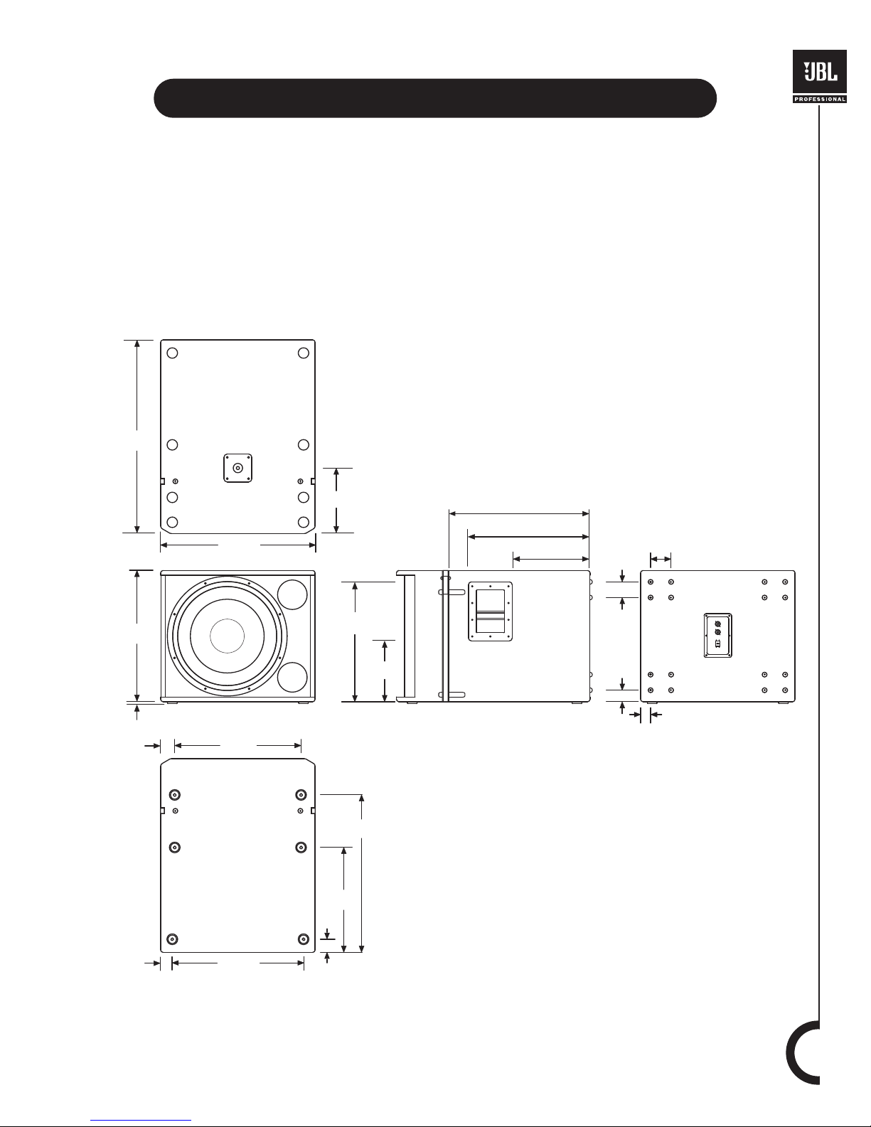
Introduction to the VRX918S
VRX918S Specifications
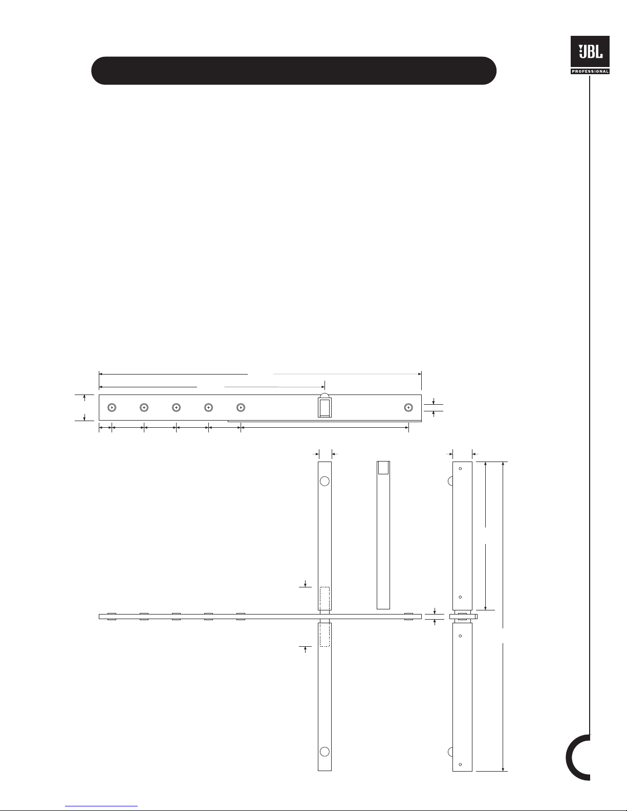
Introduction to the VRX-AF
Amplitude Shading
System Processor Tunings
Deploying the System
JBL Professional Warranty and Contact Information
3
4
5
6
7
8-9
10
11-15
16
CONTENTS
Important Safety Instructions
1. Read these instructions.
2. Keep these instructions.
3. Heed all warnings.
4. Follow all instructions.
5. Do not use this apparatus near water.
6. Clean only with a dry cloth.
7. Do not block any ventilation openings. Install in accordance with manufac-
turer’s instructions.
8. Do not install near any heat sources such as radiators, heat registers,
stoves, or other apparatus that produce heat.
9. Only use attachments / accessories specified by the manufacturer.
10. Use only with a cart, stand, bracket, or table
specified by the manufacturer or sold with the appara-
tus. When a cart is used, use caution when moving
the cart / apparatus combination to avoid injury from
tip-over.
11. Refer all servicing to qualified service personnel. Servicing is required when
an apparatus has been damaged in any way, such as power-cord or plug
is damaged, liquid has been spilled, or objects have fallen into the appara-
tus, the apparatus has been exposed to rain or moisture, does not operate
normally, or has been dropped.
12. To reduce the risk of fire or electric shock, do not expose this apparatus to
rain or moisture.
13. Hearing damage, prolonged exposure to excessive SPL, the loudspeaker
is easily capable of generating sound pressure levels (SPL) sufficient to
cause permanent hearing damage to performers, production crew and
audience members. Caution should be taken to avoid prolonged exposure
to SPL in excess of 90 dB.
The VRX Series loudspeakers covered by this
manual are not intended for fixed installation in
outdoor or high moisture environments. Moisture
can damage the speaker cone and surround
and cause corrosion of electrical contacts and
metal parts. Avoid exposing the speakers to
direct moisture. Keep speakers out of extended
or intense direct sunlight. The driver suspension
will prematurely dry out and finished surfaces may
be degraded by long-term exposure to intense
ultra-violet (UV) light.
The VRX Series speakers can generate considerable
energy. When placed on a slippery surface such as
polished wood or linoleum, the speaker may move
due to its acoustical energy output. Precautions
should be taken to assure that the speaker does not
fall off a stage or table on which it is placed.
CAUTION
RISK OF ELECTRIC SHOCK
DO NOT OPEN!
ATTENTION
RISQUE DE CHOC ÉLECTRIQUE
NE PAS ENLEVER!
DO NOT EXPOSE
TO RAIN OR MOISTURE!
NE PAS EXPOSER Á
LA PLUIE NI ÁL'HUMIDITÉ!
2
Patents
VRX series products are manufactured and sold
under U.S. patents 5,748,760; 6,112,847; 6,394,223
and 6,847,726.
2.VRX932LA_Final7.qxd 11/1/05 11:46 AM Page 2

INTRODUCTION TO THE VRX932LA
The VRX932LA is a two-way, line-array loudspeaker system intended for use in arrays of up to six enclosures.
Three high-frequency drivers are mounted to the Constant Curvature waveguide which is designed so that
multiple enclosures may be arrayed with no discontinuity in the vertical coverage pattern. As a result, the array
will behave in much the same way as would a single loudspeaker. Array coverage may be adjusted by means
of the Array Configuration Selector (ACS), a feature that provides amplitude shading (see page 8 & 9) when the
system is used in passive mode. Integral rigging hardware, a dual angle pole socket and an accessory array
frame provide for a variety of mounting and suspension options.
*NOTE: The VRX932LA-WH is designed for fixed install situations where white loudspeakers are required to
match existing decor. White versions therefore do not have handles, feet or pole mount features.
3
343 mm
13.5 in
376 mm
14.8 in
597 mm
23.5 in
1325 mm
52.2 in
15º
VRX932LA
Dimensional Drawings
11/18/04
JBLPROFESSIONAL
Northridge, CA USA
Madein USA
Serial No.
BI-AMP
PASSIVE
PARALLEL
VRX932LA
BI-AMP
±1 LF: 8
±2HF: 6
W
W
PASSIVE
±1 IN: 6
±2N/C
W
Single
Speaker
or
Short
Throw
Mid
Throw
Long
Throw
Array Configuration Selector -HF Output Level
Equippedwith Differential DriveÆ
TransducerTechnology U.S. PATENT 5,748,760
Dimensional Drawings for VRX932LA
343 mm
13.5 in
376 mm
14.8 in
597 mm
23.5 in
1325 mm
52.2 in
15º
VRX932LA
Dimensional Drawings
11/18/04
JBLPROFESSIONAL
Northridge, CA USA
Madein USA
Serial No.
BI-AMP
PASSIVE
PARALLEL
VRX932LA
BI-AMP
±1 LF: 8
±2HF: 6
W
W
PASSIVE
±1 IN: 6
±2N/C
W
Single
Speaker
or
Short
Throw
Mid
Throw
Long
Throw
Array Configuration Selector -HF Output Level
Equippedwith Differential DriveÆ
TransducerTechnology U.S. PATENT 5,748,760
2.VRX932LA_Final7.qxd 11/1/05 11:46 AM Page 3

SPECIFICATIONS
VRX932LA - 12¨, two-way, line-array loudspeaker system
System Type: 12" two-way, line array loudspeaker system
Frequency Range (-10 dB) : 57 Hz - 20 kHz
Frequency Response (±3 dB) : 75 Hz - 20 kHz
Coverage Pattern: 100º x 15º nominal (horizontal x vertical)
Crossover Modes: Bi-amp / passive, externally switchable
Crossover Frequency: 1.2 kHz
Power Rating Passive: 800 W / 1600 W / 3200 W
(Continuous / Program / Peak): Bi-amp LF: 800 W / 1600 W / 3200 W
Bi-amp HF: 75 W / 150 W / 300 W
System Maximum SPL : 130 dB SPL peak (passive)
LF: 130 dB
HF: 139 dB
System Sensitivity (1w @ 1m): 95 dB SPL (passive mode)
LF: 95 dB
HF: 114 dB
LF Driver: 1 x JBL 2262H 305 mm (12 in) Differential Drive® woofer with neodymium-magnet and
dual voice-coils
HF Driver: 3 x JBL 2407J, 25.4 mm (1 in) voice-coil, neodymium magnet compression driver
Nominal Impedance: Passive: 8 ohm
Bi-amp LF: 8 ohms
Bi-amp HF: 8 ohms
Active Tunings: Tunings available at www.jblpro.com
Enclosure: 18 mm, 11-ply birch plywood.
Suspension / Mounting: Suspension requires optional VRX-AF line-array frame kit / Dual angle 35 mm pole socket /
10 mm eyebolt
Finish: Black DuraFlex™ finish
Grille: Powder coated, black, 16-gauge perforated steel with acoustically transparent foam
Input Connectors: Neutrik ® Speakon® NL-4 (x2)
Dimensions (H x W x D): 349 mm x 597 mm x 381 mm (13.75 in x 23.5 in x 15.0 in)
Net Weight: 21.8 kg (48 lb)
OptionalAccessories: VRX-AF: Suspension array frame
SS2-BK: Tripod speaker stand
Eyebolt Kit Part # 229-00009-01
4
Functional Block Diagram
SHORT THROW
MID THROW
LONG THROW
1+
1-
2-
2+
1+
1-
2-
2+
1+
1-
2-
2+
1+
1-
2-
2+
NL4
INPUT
NL4
INPUT
HPF
LPF
PASSIVE
MODE
BI-AMP
MODE
-3 dB
0 dB
+3 dB
NL4
INPUT
NL4
INPUT
+
+
+
+
+
+
+
+
-
-
-
-
-
-
-
-
SHORT THROW
MID THROW
LONG THROW
1+
1-
2-
2+
1+
1-
2-
2+
1+
1-
2-
2+
1+
1-
2-
2+
NL4
INPUT
NL4
INPUT
HPF
LPF
PASSIVE
MODE
BI-AMP
MODE
-3 dB
0 dB
+3 dB
NL4
INPUT
NL4
INPUT
+
+
+
+
+
+
+
+
-
-
-
-
-
-
-
-
Dimensional Drawings for VRX918S
1
1
3
3
2
1. “Frequency Range” and “Frequency Response” are based on half-space conditions.
2. IEC filtered noise with 6 dB crest factor, 2 hours.
3. Calculated based on power rating and sensitivity.
4. White version does not include pole mount feature.
5. White version uses JBL Pro White Duraflex Finish.
6. White version grille is powdercoated white with acoustically transparent white cloth backing.
4
5
6
2.VRX932LA_Final7.qxd 11/1/05 11:46 AM Page 4

546 mm
(21.5 in)
464 mm
(18.25 in)
298 mm
(11.75 in)
38 mm
(1.5 in)
457 mm
(18.0 in)
235 mm
(9.25 in)
489 mm
(19.25 in)
508 mm
(20.0 in)
56 mm
(2.2 in)
45 mm
(1.8 in)
51 mm
(2.0 in)
406 mm
(16.0 in)
610 mm
(24.0 in)
8 mm
(0.3 in)
508 mm
(20.0 in)
597 mm
(23.5 in)
750 mm
(29.5 in)
254 mm
(10.0 in)
44 mm
(1.75 in)
60 mm
(2.37 in)
79 mm
(3.13 in)
5
INTRODUCTION TO THE VRX918S
The VRX918S is a compact single 18˝ direct radiating subwoofer intended for use in suspended arrays or
ground-supported applications. The suspension system is designed for full compatibility with the VRX932LA
line-array speaker system and the VRX-AF array frame.
*NOTE: The VRX918S-WH is designed for fixed installation situations where white loudspeakers are required to
match existing decor. White versions therefore do not have handles, feet or pole mount features.
Dimensional Drawings for VRX918S
2.VRX932LA_Final7.qxd 11/1/05 11:46 AM Page 5

SPECIFICATIONS
VRX918S - 18” Subwoofer
System Type:
Frequency Range (-10 dB) :
Frequency Response (±3 dB) :
Input Connection Modes:
Recommended Crossover
Frequencies:
Power Rating
(Continuous / Program / Peak):
Maximum SPL :
Sensitivity (1w @ 1m):
LF Driver:
Nominal Impedance:
Active Tunings:
Mounting:
Suspension / Mounting:
Enclosure:
Finish:
Grille:
Input Connectors:
Dimensions (H x W x D):
Net Weight:
OptionalAccessories:
6
VRX918S
18" bass-reflex subwoofer
31 Hz - 220 Hz
34 Hz - 220 Hz
Switchable, +1/-1 or +2/-2
80 Hz, 24 dB / octave HPF; 80 Hz, 24 dB / octave LPF
800 W / 1600 W / 3200 W
130 dB SPL peak
95 dB SPL
1 x JBL 2268H 457 mm (18 in) Differential Drive woofer
8 ohms
Use SRX718S tunings
Top mounted M20 threaded socket for optional SS4-BK pole
Optional VRX-AF line array frame kit or 10mm eyebolt (Part #229-00009-01)
Rectangular, 18 mm, 13-ply birch plywood
Black DuraFlex finish
Powder coated, 16-gauge perforated steel with acoustical transparent charcoal foam backing.
Neutrik® Speakon® NL-4 (x2)
508 mm x 597 mm x 749 mm; (20.0 in x 23.5 in x 29.5 in)
37 kg (81 lb)
SRX718S-CVR: Pull-over padded cover SS4-BK: Adjustable, heavy-duty pole,
M20 thread to 35 mm WK-4: Caster kit
VRX-AFArray Frame
Eyebolt Kit (Part #229-00009-01)
Functional Block Diagram
1
1
3
2
4
5
6
1. “Frequency Range” and “Frequency Response” are based on half-space conditions.
2. IEC filtered noise with 6 dB crest factor, 2 hours.
3. Calculated based on power rating and sensitivity.
4. White version does not include pole mount feature.
5. White version uses JBL Pro White Duraflex Finish.
6. White version grille is powdercoated white with acoustically transparent white cloth backing.
2.VRX932LA_Final7.qxd 11/1/05 11:46 AM Page 6

7
INTRODUCTION TO THE VRX-AF
The VRX-AF is an array frame designed to be used for suspension of the VRX932LA and VRX918S
loudspeaker systems. The optional array frame kit includes the following items:
• 1 x center frame
• 2 x side arms
• 4 x quick release pins
•2 x drop levers
• 2 x 3/8˝ shackles
51 mm
(2.0 in)
292 mm
(11.5 in)
117mm
(4.6 in)
610 mm
(24.0 in)
13 mm
(0.5 in)
10 mm
(0.4 in)
25 mm
(1.0 in)
38 mm
(1.5 in)
25 mm
(1.0 in)
65 mm
(2.5 in)
65 mm
(2.5 in)
65 mm
(2.5 in)
65 mm
(2.5 in)
330 mm
(13.0 in)
445 mm
(17.5 in)
635 mm
(25.0 in)
Working Load Limit
The VRX-AF and VRX932LA-AF array frames have been precisely engineered to work together with the VRX
line of speakers as a system. The working load limit depends upon the configuration of array frame and speak-
ers being suspended. Please refer to the "DEPLOYING THE SYSTEM" section of this user guide for maximum
allowable load limits when using the VRX-AF or VRX932LA-AF frame.
The VRX-AF and VRX932LA-AF array frames have been specifically designed to work only with the VRX speak-
er line. Use of the array frames in any manner other than as described in this manual could result in damage to
the frame and pose a risk of injury or death.
Please refer to page 14 and 15 of the “DEPLOYING THE SYSTEM” section of this user guide for important safe-
ty and related information regarding the use of the array frame.
2.VRX932LA_Final7.qxd 11/1/05 11:46 AM Page 7

AMPLITUDE SHADING
Amplitude Shading
Amplitude shading is a technique that allows the coverage pattern of a loudspeaker array to be shaped by
adjusting the relative acoustic output of some of the devices in the array. Most often, array shading involves
only the mid and high-frequency sections of the array. In a simple system consisting of three VRX932LAs, the
lower speaker (which covers the nearest listeners) may have its high-frequency output reduced. At the same
time, the upper speaker may have its high frequency output increased. The overall sound-power in the room
is unchanged but the distribution of acoustic energy to the audience is far more uniform. Amplitude shading of
a VRX932LA array may be accomplished in passive or bi-amplified systems.
Array Configuration Selector (ACS)
In passive mode, the Array Configuration Selector may be used. The -3 dB position will typically be used for
the speaker(s) in an array that are covering the nearest listening area. The +3 dB position will be used for the
speaker(s) covering the more distant areas; or to compensate for the low-frequency build-up resulting from
mutual coupling of multiple woofers in an array.
BI-AMP
PASSIVE
Single
Speaker
or
Short
Throw
Mid
Throw
Long
Throw
Array Configuration Selector - HF Output Level
EquippedwithDifferential DriveÆ
Transducer Technology U.S. PATENT 5,748,760
JBL PROFESSIONAL
Northridge, CA USA
Made in USA
Serial No.
BI-AMP
PASSIVE
PARALLEL
VRX932LA
BI-AMP
±1 LF:8
±2 HF:6
W
W
PASSIVE
±1 IN:6
±2 N/C
W
Single
Speaker
or
Short
Throw
Mid
Throw
Long
Throw
Array Configuration Selector - HF Output Level
EquippedwithDifferential DriveÆ
Transducer Technology U.S. PATENT 5,748,760
BI-AMP
PASSIVE
Single
Speaker
or
Short
Throw
Mid
Throw
Long
Throw
Array Configuration Selector - HF Output Level
EquippedwithDifferential DriveÆ
Transducer Technology U.S. PATENT 5,748,760
BI-AMP
PASSIVE
Single
Speaker
or
Short
Throw
Mid
Throw
Long
Throw
Array Configuration Selector - HF Output Level
EquippedwithDifferential DriveÆ
Transducer Technology U.S. PATENT 5,748,760
Short Throw (-3 dB)
BI-AMP
PASSIVE
Single
Speaker
or
Short
Throw
Mid
Throw
Long
Throw
Array Configuration Selector - HF Output Level
EquippedwithDifferential DriveÆ
Transducer Technology U.S. PATENT 5,748,760
JBL PROFESSIONAL
Northridge, CA USA
Made in USA
Serial No.
BI-AMP
PASSIVE
PARALLEL
VRX932LA
BI-AMP
±1 LF:8
±2 HF:6
W
W
PASSIVE
±1 IN:6
±2 N/C
W
Single
Speaker
or
Short
Throw
Mid
Throw
Long
Throw
Array Configuration Selector - HF Output Level
EquippedwithDifferential DriveÆ
Transducer Technology U.S. PATENT 5,748,760
BI-AMP
PASSIVE
Single
Speaker
or
Short
Throw
Mid
Throw
Long
Throw
Array Configuration Selector - HF Output Level
EquippedwithDifferential DriveÆ
Transducer Technology U.S. PATENT 5,748,760
BI-AMP
PASSIVE
Single
Speaker
or
Short
Throw
Mid
Throw
Long
Throw
Array Configuration Selector - HF Output Level
EquippedwithDifferential DriveÆ
Transducer Technology U.S. PATENT 5,748,760
Long Throw (+3 dB)
BI-AMP
PASSIVE
Single
Speaker
or
Short
Throw
Mid
Throw
Long
Throw
Array Configuration Selector - HF Output Level
EquippedwithDifferential DriveÆ
Transducer Technology U.S. PATENT 5,748,760
JBL PROFESSIONAL
Northridge, CA USA
Made in USA
Serial No.
BI-AMP
PASSIVE
PARALLEL
VRX932LA
BI-AMP
±1 LF:8
±2 HF:6
W
W
PASSIVE
±1 IN:6
±2 N/C
W
Single
Speaker
or
Short
Throw
Mid
Throw
Long
Throw
Array Configuration Selector - HF Output Level
EquippedwithDifferential DriveÆ
Transducer Technology U.S. PATENT 5,748,760
BI-AMP
PASSIVE
Single
Speaker
or
Short
Throw
Mid
Throw
Long
Throw
Array Configuration Selector - HF Output Level
EquippedwithDifferential DriveÆ
Transducer Technology U.S. PATENT 5,748,760
BI-AMP
PASSIVE
Single
Speaker
or
Short
Throw
Mid
Throw
Long
Throw
Array Configuration Selector - HF Output Level
EquippedwithDifferential DriveÆ
Transducer Technology U.S. PATENT 5,748,760
Medium Throw (0 dB)
Frequency Response
The frequency response graph represents measurements from a single VRX932LA speaker, applying the three
different ACS settings: +3dB, 0dB, -3dB.
8
2.VRX932LA_Final7.qxd 11/1/05 11:46 AM Page 8

9
Bi-Amplified System
In a bi-amplified system, array shading is accomplished by connecting separate amplifier channels to the HF
section of each VRX932LA. In larger arrays, a single amplifier channel may be used for two adjacent
loudspeakers. Array shading is then accomplished by adjusting the gain of the HF amplifier channels. For
extremely precise control over system performance, it may also be desirable to dedicate an individual system
controller output to each HF amplifier channel.
0dB
0dB
-3 dB
0
º
0 dB
0dB
-3 dB
0
º
+3 dB
0 dB
-3 dB
Audience
Array Configuration Selector (ACS)
Below is an example of applying the ACS in a three-speaker array. In this particular configuration,
the ACS on the top speaker is set at +3 dB, the middle speaker at 0 dB, and the bottom speaker -3 dB.
2.VRX932LA_Final7.qxd 11/1/05 11:46 AM Page 9

10
SYSTEM PROCESSOR TUNINGS
The following table includes the tunings for the dbx DriveRack 260. It is always a good idea to check for the
latest tunings on the JBL Pro web site at http://www.jblpro.com/pages/tunings/tunings_main.htm. If you have a
processor for which VRX tunings are not developed, the following table can serve as a starting point for setting
your processor.
Note to DriveRack PA users: The DriveRack PA does not include a POLARITY function. When using the
DriveRack PA for a tuning that requires the polarity parameter to be set to “INVERT” it will be necessary to
invert polarity at the amplifier output cable connection or by using a specially wired cable or adapter between
the processor and the amplifier channel.
Processor:
dbx DriveRack 260
Speaker Model(s):
VRX932LA
Revision Date:
03/02/05
bi-amp full range: 1x VRX932LA 2x VRX932LA 3-6x VRX932LA xover for Sub
MID HIGH MID HIGH MID HIGH LOW MID
Input Source A A A A A A A A
COMP/LIMIT
Output Gain 0dB -15 dB 0.0dB -5.5dB 0.0dB -5.5dB 2.0 dB 0dB
Output Limit
DELAY & POLARITY
Output Delay 0.0ms 0.25ms 0.0ms .25ms 0.0ms .25ms 0.0 ms 0.0 ms
Output Delay Link
Polarity NORMAL INVERT NORMAL INVERT NORMAL INVERT NORMAL NORMAL
XOVER
Output Lo Shape BUT18 LR24 BUT18 LR24 BUT18 LR24 BUT18 LR48
Output Lo Frequency 46.8 Hz 1.09 KHz 46.8Hz 1.091kHz 46.8Hz 1.091kHz 31.3 Hz 81.1Hz
Output Hi Shape LR48 BUT6 LR48 LR48 BW6 LR48 BUT6
Output Hi Frequency 1.41KHz OUT 1.414kHz OUT 1.414kHz OUT 81.1Hz OUT
EQ
Output EQ1 Type BELL BELL BELL BELL BELL BELL BELL
Output EQ1 Frequency 630 Hz 3.89 KHz 648Hz 2.83kHz 648Hz 2.83kHz 68 Hz
Output EQ1 +/- -2.5 dB -6dB -3.0dB -12.0dB -3.0dB -12.0dB 2 dB
Output EQ1 Bandwidth 3.4 Q 1.38 Q 2.996Q 1.215Q 2.996Q 1.215Q Q: 5
Output EQ2 Type BELL LO SHELF BELL BELL BELL BELL
Output EQ2 Frequency 2.31 KHz 136Hz 16.0kHz 841Hz 13.1kHz 41.7 Hz
Output EQ2 +/- -4.5 dB 5.0dB 5.0dB 2.5dB 5.0dB 1.5 dB
Output EQ2 Bandwidth 2.63 Q
Slope 4.5dB/Oc
t2.315Q 2.996Q 2.315Q Q: 5
Output EQ3Type BELL BELL BELL
Output EQ3 Frequency 1.00 KHz 1.73kHZ 1.73kHZ
Output EQ3 +/- -12.0 dB -3.0dB -3.0dB
Output EQ3 Bandwidth 7.38 Q
2.996Q 2.996Q
Output EQ4 Type HI SHELF BELL BELL
Output EQ4 Frequency 12.3 KHz 1.0kHz 1.0kHz
Output EQ4 +/- 8.0dB -9.0dB -9.0dB
Output EQ4 Bandwidth 9.0dB slope 12.364Q 12.364Q
> using equal gain amplifiers <
NOTE:
For VRX932LA systems in passive mode use the suggested Xover For Sub filter as is and adjust the subwoofer gain for desired performance.
For VRX932LA systems in bi-amp mode use the suggested Xover For Sub filter settings and implement it to your matching bi-amp fullrange table.
2.VRX932LA_Final7.qxd 11/1/05 11:46 AM Page 10

11
DEPLOYING THE SYSTEM
The VRX932LA is a flexible speaker system that can be deployed in ground-supported or suspended
applications. The following information will help you set up your VRX932LA system safely and effectively.
POLE AND TRIPOD SAFETY WARNINGS!
When using stands or poles, be sure to observe the following precautions:
•Check the stand or pole specification to be certain the device is designed to support the weight of the
speaker. Observe all safety precautions specified by the manufacturer.
•Be certain that the surface on which the system is to be stacked is flat, stable and solid.
•Route cables so that performers, production crew, and audience will not trip and topple the speakers.
•Inspect the stand (or pole and associated hardware) before each use and do not use equipment with
worn, damaged, or missing parts.
•Do not attempt to place more than two VRX932LA loudspeakers on a stand or pole.
•When mounting two VRX932LA speakers on a pole or tripod, integral rigging hardware must be used to
secure the speakers to each other.
•Always be cautious when deploying the system outdoors. Unexpected winds may topple a system. It may
be necessary to place additional weight (i.e. sandbags) on the base of the stand to improve stability. Avoid
attaching banners or similar items to any part of a speaker system. Such attachments could act as a sail
and topple the system.
•Unless you are confident that you can handle the weight of the speaker, ask another person to help you
get it onto the tripod stand or pole.
•One or two VRX918S loudspeakers may be mounted onto either a JBL SS2-BK tripod stand or a JBL
SRX718S or VRX918S subwoofer with an SS4-BK adjustable pole. Do not stack more than two
VRX932LA speakers on a pole. When pole mounting on the SS4-BK, the pole is not to be extended
beyond 1448 mm (57 in).
Single VRX932LA
Asingle VRX932LA may be used on a tripod stand (JBL SS2BK) or on a pole
over a subwoofer (JBL SS4BK and VRX918S). The use of a subwoofer is
recommended for applications requiring more low-frequency power and extension.
Usually, the Array Configuration Selector (ACS) switches on the input panel should
be set to the "Short Throw (-3 dB)" position when a single speaker is used.
The VRX932LA includes a dual angle 35 mm pole mount socket. By selecting the
appropriate pole socket and adjusting the height of the tripod or pole, optimum
coverage may be achieved. Ideally, the audience should not be able to see either
he bottom or the top surfaces of the speaker. This will insure that all listeners are
within the "included coverage angle" of the loudspeaker. The rear pole-socket will
position the speaker with the baffle 2.5° to the floor while the forward socket will
position the speaker with the baffle angled down by 15°. System illustration shows
available JBL SS2BK tripod stand.
*NOTE: VRX932LA-WH does not include pole mount features and is designed
specifically for fixed installations
2.VRX932LA_Final7.qxd 11/1/05 11:46 AM Page 11

12
Dual VRX932LA
Unlike most conventional speakers, the VRX932LA is designed so that a pair of
speakers may be safely mounted onto a pole or tripod stand. For most applications,
the forward socket of the dual angle pole socket will be used. This will tilt the lower
of the two speakers at a 15° down-angle (providing coverage of the near listeners)
while the upper speaker will face straight out (covering the more distant areas).
Ideally, the listeners should not be able to see either the bottom or the top surfaces
of the two-speaker array. Usually, the Array Configuration Selector (ACS) switches
on the lower speaker's input panel should be set to the "Short Throw (-3 dB)"
position while the upper speaker will be set to either "Short Throw (-3 dB)" or
"Mid Throw (0 dB)".
Place the speakers on the pole or tripod one at a time. Be sure to lock the two
speakers together using the integral rigging hardware (see below). System illustration
shows available JBL SS4BK speaker pole and SRX718S subwoofers. Do not stack
more than two VRX932LA speakers on a pole.
Locking (2) VRX932LA Loudspeakers Together
Any time two or more VRX932LAs are arrayed together, they must be mechanically secured to each other using
the integral rigging frame and supplied quick release pins. See the diagram below for details. WARNING: Only
the correct quick release pins supplied by JBL are to be used.
2.VRX932LA_Final7.qxd 11/1/05 11:46 AM Page 12

13
Correct use of all rigging hardware is required for secure system suspension. Careful calculations should
always be performed to ensure that all components are used within their Maximum Load Limit before the array
is suspended. Never exceed the maximum recommended load ratings. Prior to suspending the system, an
expert, trained and experienced in flying speaker systems should be consulted. Research and understand the
codes, practices, and requirements in the venues where you intend to operate your sound system.
Inspection & Maintenance
Before suspending or pole mounting any speaker system always inspect all components (enclosure, rigging
frames, pins, eyebolts, track fittings, etc.) for cracks, deformations, corrosion, missing, loose or damaged
parts that could reduce strength and safety of the array. Do not suspend or pole mount the speaker until the
proper corrective action has been taken. Installed systems should be inspected at least annually. The inspection
shall include a visual survey of all corners and load bearing surfaces for signs of cracking, water damage,
de-lamination, or any other condition that may decrease the strength of the loudspeaker enclosure. Accessory
rigging hardware provided with or for the JBL VRX932LA or VRX918S loudspeaker must be inspected for fatigue
at least annually or as required by local ordinance. For all other hardware and fittings, refer to the hardware
manufacturer's inspection and maintenance guidelines for process.
Are You New to Rigging?
If you are new to rigging, you should do the following:
•Read and study JBL Technical Note Volume 1, Number 14: Basic Principles for Suspending
Loudspeaker Systems (available at http://www.jblpro.com/pub/technote/tn_v1n14.pdf).
•Know the rules for safe rigging.
•Attend a safe rigging seminar, such as that presented by professionals like Rigging Seminars™
(www.riggingseminars.com) or by Chain Motor Hoist manufacturers like Columbus McKinnon Corp.
(manufacturers of the C/M Lodestar).
•Meet and establish a relationship with a licensed mechanical or structural engineer. Get in the habit of
asking them questions instead of guessing about their answers. Learn from what they tell you.
•Meet and discuss this aspect of your business with your Insurance Agent.
Attachment to Structures
A licensed Professional Engineer must approve the placement and method of attachment to the structure prior
to the installation of any overhead object. The following performance standards should be provided to the
Professional Engineer for design purposes; Uniform Building Code as applicable, Municipal Building Code as
applicable, and Seismic Code as applicable. The installation of the hardware and method of attachment must
be carried out in the manner specified by the Professional Engineer. Improper installation may result in
damage, injury or death.
JBL is not responsible for the application of its products for any purpose or the misuse of this information for any
purpose. Furthermore, JBL is not responsible for the abuse of its products caused by avoiding compliance with
inspection and maintenance procedures or any other abuse.
SUSPENSION SAFETY WARNINGS!
2.VRX932LA_Final7.qxd 11/1/05 11:46 AM Page 13

Maximum Array Size
There are two variations of the VRX array frame. The VRX-AF which is dark gray in color supersedes the
VRX932AF-LA (which is black). Before suspending a VRX array, determine which version of the array frame
you have and consult the table below to determine the maximum number of VRX932LA and VRX918S speakers
that may be safely suspended. The VRX918S subwoofers must always be at the top of the array.
VRX-AF Array Frame
The following table defines the maximum number of speakers that may be suspended using the VRX-AF frame.
A minimum design factor of 7:1 is maintained for all speaker configurations at or below those indicated in the
table.
VRX932LA-AF Array Frame
The following table defines the maximum number of speakers that may be suspended using the VRX932LA-AF
frame. A minimum design factor of 7:1 is maintained for all speaker configurations at or below those indicated in
the table.
Installing the Array Frame
The VRX932LA-AF or VRX-AF Array Frames (see previous section) are designed specifically for suspension
of VRX932LA and VRX918S arrays. The array frame is attached to the internal rigging of the VRX918S or
VRX932LA using the provided Quick Release Pins [Warning: Do not use any substitute for these pins].
1. Begin by attaching the two side arms (A) to either side of the center frame. Use a pair of the provided Quick
Release Pins (B) to attach the arms to the frame. Note: Side arms should be attached with the rubber bumper
facing up and away from the center frame. The center frame is installed with the rubber gasket toward the
enclosure and the label right side up. [NOTE: The arms of the VRX932LA-AF and VRX-AF are deliberately
designed so as not to be interchangeable.]
2. Place the entire array frame on top of the VRX932LA or VRX918S and flip up the drop levers (C) found on both
sides of the speaker to be received by the array frame arms.
3. Once the drop levers on the speaker are received by the
array frame, use a pair of the provided Quick Release Pins
(D) to attach the drop levers to the array frame.
14
(C)
(A) (D) (B) (A) (D)
Maximum number of VRX918S in array
Maximum number of VRX932LA in array
6 5 4 3 2 1 0
VRX-AF Array Frame
VRX932LA-AF Array Frame
0 1 2 3 4 5 6
Maximum number of VRX918S in array
Maximum number of VRX932LA in array
4 3 2 1 0
1 2 3 4 5
2.VRX932LA_Final7.qxd 11/1/05 11:46 AM Page 14

Ground-Stacked, Upward Firing Arrays
Applications such as covering stadium bleachers from the playing field may be addressed by installing the
VRX932LA-AF array frame to the bottom of the array.
Up to four VRX932LA loudspeakers may be locked together and
ground stacked using the VRX-AF array frame kit, as shown.
[Warning: Do not ground stack more than four VRX932LA
loudspeakers in one array]. When ground stacking VRX932LA
loudspeakers, use The VRX-AF array frame as the base
(as shown) by attaching the loose drop levers, included in the
array frame kit, to the lower rigging bar on the VRX932LA
loudspeaker. When stacking the loudspeakers together, make
sure each loudspeaker is locked together. Be certain that the
surface on which the system is to be stacked is flat, stable and
solid. Up to 4 VRX932LA speakers may be stacked on top of one
or two VRX918S subwoofers. The subwoofers must be locked to
each other using the integral rigging hardware. The VRX932LA
speakers may then be attached to the subwoofers using the same
process described above.
15
Suspension in Permanent Installations
For permanent installation applications a VRX array may be suspended using M10 eyebolts. Only load-rated,
forged shoulder eyebolts are to be used. A kit consisting of three (3) forged shoulder eyebolts is available from
JBL Professional as part number 229-00009-01. Suspension of the VRX array must employ both top attach-
ment points. The VRX918S subwoofers must always be at the top of the array.
Eyebolt Suspension
The following table defines the maximum number of speakers that may be suspended using the two M10 eye-
bolt attachment points provided on the cabinets. A minimum design factor of 7:1 is maintained for all speaker
configurations at or below those indicated in the table.
Eyebolt Suspension Array Frame Suspension
Maximum number of VRX918S in array
Maximum number of VRX932LA in array
5 4 3 2 1 0
0 2 4 5 6 6
2.VRX932LA_Final7.qxd 11/1/05 11:46 AM Page 15

JBL WARRANTY AND CONTACTS
Mailing Address:
JBL Professional
8500 Balboa Blvd.
Northridge, CA 91329 USA
Shipping Address:
JBL Professional
8370 Balboa Blvd., Dock D
Northridge, CA 91329 USA
(Do not return product to this address without
first obtaining prior authorization from JBL)
Customer Service:
Monday through Friday
8:00am - 5:00pm
Pacific Standard Time In the U.S.A.
(800) 8JBLPRO (800.852.5776)
www.jblproservice.com
On the World Wide Web:
www.jblpro.com
Outside the USA:
Contact the JBL Professional Distributor in your area. A
complete list of JBL Professional international distributors is
provided at our U.S.A.website - www.jblpro.com
Product Registration:
Register your product online at www.jblpro.com/registration
The JBL Warranty on professional loudspeaker products (except for enclosures) remains in effect for five
years from the date of the first consumer purchase. JBL amplifiers are warranted for three years from the
date of original purchase. Enclosures and all other JBL products are warranted for two years from the date
of original purchase.
Who Is Protected by This Warranty?
Your JBL Warranty protects the original owner and all subsequent owners so long as: A.) Your JBL product
has been purchased in the Continental United States, Hawaii or Alaska. (This Warranty does not apply to JBL
products purchased elsewhere except for purchases by military outlets. Other purchasers should contact the
local JBL distributor for warranty information.); and B.) The original dated bill of sale is presented whenever
warranty service is required.
What does the JBL Warranty cover?
Except as specified below, your JBL Warranty covers all defects in material and workmanship. The following
are not covered: Damage caused by accident, misuse, abuse, product modification or neglect; damage
occurring during shipment; damage resulting from failure to follow instructions contained in your Instruction
Manual; damage resulting from the performance of repairs by someone not authorized by JBL; claims based
upon any misrepresentations by the seller; any JBL product on which the serial number has been defaced,
modified or removed.
Who Pays for What?
JBL will pay all labor and material expenses for all repairs covered by this warranty. Please be sure to save
the original shipping cartons because a charge will be made if replacement cartons are requested. Payment
of shipping charges is discussed in the next section of this warranty.
How to Obtain Warranty Performance
If your JBL product ever needs service, write or telephone us at JBL Incorporated (Attn: Customer Service
Department), 8500 Balboa Boulevard, PO. Box 2200, Northridge, California 91329 (818/893-8411). We may
direct you to an authorized JBL Service Agency or ask you to send your unit to the factory for repair. Either
way, you'll need to present the original bill of sale to establish the date of purchase. Please do not ship your
JBL product to the factory without prior authorization. If transportation of your JBL product presents any unusual
difficulties, please advise us and we may make special arrangements with you. Otherwise, you are responsible
for transporting your product for repair or arranging for its transportation and for payment of any initial shipping
charges. However, we will pay the return shipping charges if repairs are covered by the warranty.
2.VRX932LA_Final7.qxd 11/1/05 11:46 AM Page 16
Other manuals for VRX932LA
2
This manual suits for next models
5
Table of contents
Other JBL Speakers manuals

JBL
JBL FLIP3 User manual

JBL
JBL CINEMA BASE User manual

JBL
JBL Performance Specialist SS6 User manual

JBL
JBL CFSERIES User manual

JBL
JBL j50 User manual

JBL
JBL JRX112M User manual

JBL
JBL Reference 220 Installation and operation manual

JBL
JBL CONTROL ONE OUTDOOR User manual

JBL
JBL Pulse2 Operating and maintenance instructions

JBL
JBL 4310 User manual