jcb TM320 User manual

Copyright © 2004 JCB SERVICE. All rights reserved. No part of this publication may be reproduced, stored in a retrieval system, or transmitted in any form or by any other means,
electronic, mechanical, photocopying or otherwise, without prior permission from JCB SERVICE.
World Class
Customer Support
9813/4700-1
Publication No.
Issued by JCB Technical Publications, JCB Service, World Parts Centre, Beamhurst, Uttoxeter, Staffordshire, ST14 5PA, England. Tel +44 1889 590312 Fax +44 1889 593377
Service Manual
TM320
Section 1 - General Information
Section 2 - Care and Safety
Section 3 - Routine Maintenance
Section B - Body and Framework
Section C - Electrics
Section E - Hydraulics
Section F - Transmission
Section G - Brakes
Section H - Steering
Section K - Engine
Section M - Network Systems

Copyright © 2004 JCB SERVICE. All rights reserved. No part of this publication may be reproduced, stored in a retrieval system, or transmitted in any form or by any other means,
electronic, mechanical, photocopying or otherwise, without prior permission from JCB SERVICE.
World Class
Customer Support
9813/4700-1
Publication No.
Issued by JCB Technical Publications, JCB Aftermarket Training, Woodseat, Rocester, Staffordshire, ST14 5BW, England. Tel +44 1889 591300 Fax +44 1889 591400
Section 1
General Information
Service Manual - TM320
Section 1 - General Information
Section 2 - Care and Safety
Section 3 - Routine Maintenance
Section B - Body and Framework
Section C - Electrics
Section E - Hydraulics
Section F - Transmission
Section G - Brakes
Section H - Steering
Section K - Engine
Section M - Network Systems

Section 1 - 1
1-0 1-0
9813/4700-1
Notes:

Page No.Contents
Section 1 - General Information
1-i 1-i
Section 1 -i
Introduction
About this Manual ...................................................................................... 1-1
Machine Model and Serial Number .......................................................1-1
General ..................................................................................................1-1
Name and Address of the Manufacturer ...............................................1-1
Using this Manual ..................................................................................1-1
Left Side, Right Side ..............................................................................1-1
Cross References ..................................................................................1-1
Product Compliance ..............................................................................1-1
Identifying Your Machine ........................................................................... 1-3
Machine Identification Plate ..................................................................1-3
Typical Product Identification Number ...................................................1-3
Component Identification .......................................................................1-4
Torque Settings
Zinc Plated Fasteners and Dacromet Fasteners ....................................... 1-8
Introduction ............................................................................................1-8
Bolts and Screws ...................................................................................1-8
Hydraulic Connections ............................................................................. 1-12
'O' Ring Face Seal System ..................................................................1-12
'Torque Stop' Hose System .................................................................1-15
Service Tools
Numerical List .......................................................................................... 1-16
Tool Detail Reference .............................................................................. 1-17
Section B - Body and Framework ........................................................1-17
Section C - Electrics ............................................................................1-21
Section E - Hydraulics .........................................................................1-24
Section H - Steering ............................................................................1-32
Section K - Engine ...............................................................................1-33
Service Consumables
Sealing and Retaining Compounds ......................................................... 1-36
Terms and Definitions
Colour Coding .......................................................................................... 1-38
Hydraulic Schematic Colour Codes .....................................................1-38

Page No.Contents
Section 1 - General Information
1-ii 1-ii

Section 1 - General Information
1-1 1-1
9813/4700-1
Introduction
About this Manual
Machine Model and Serial Number
This manual provides information for the following
model(s) in the JCB machine range:
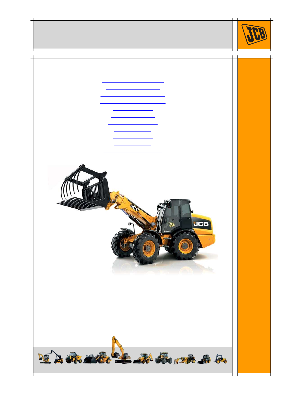
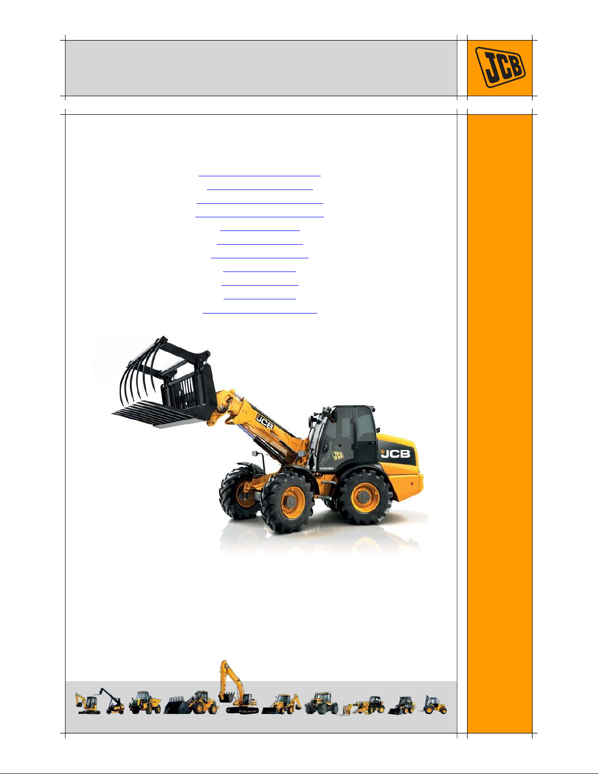
TM320 from machine serial number 2420601 to 2420800.
General
Before you start using the product, you must know how the
product operates. Use this part of the manual to identify
each control lever, switch, gauge, button and pedal. Do not
guess, if there is anything you do not understand, ask your
JCB dealer.
Name and Address of the Manufacturer
JCB Excavators Limited, Lakeside Works, Rocester,
Uttoxeter, United Kingdom, ST145JP.
Using this Manual
T1-044
This manual is arranged to give you a good understanding
of the machine and its safe operation. It also contains
maintenance information and specification data. Read this
manual from front to back before using the machine for the
first time. Particular attention must be given to all the safety
aspects of operating and maintaining the machine.
If there is anything you are not sure about, ask your JCB
distributor or employer. Do not guess, you or others could
be killed or seriously injured.
General warnings in this chapter are repeated throughout
the book, as well as specific warnings. Read all the safety
statements regularly, so you do not forget them.
Remember that the best operators are the safest
operators.
The illustrations in this manual are for guidance only.
Where the machines differ, the text and or the illustration
will specify.
This manual contains original instructions, verified by the
manufacturer (or their authorised representative).
The manufacturer's policy is one of continuous
improvement. The right to change the specification of the
machine without notice is reserved. No responsibility will
be accepted for discrepancies which may occur between
specifications of the machine and the descriptions
contained in this publication.
All optional equipment included in this manual may not be
available in all territories.
Left Side, Right Side
In this manual, 'left' A and 'right' B mean your left and right
when you are seated correctly in the machine.
C087420
Fig 1.
Cross References
T1-004_2
In this publication, page cross references are made by
presenting the subject title printed in bold, italic and
underlined. It is preceeded by the 'go to' symbol. The
number of the page upon which the subject begins, is
indicated within the brackets. For example: Cross
References ( 1-1).
Product Compliance
T1-055
Your JCB machine was designed to comply with the laws
and regulations applicable at the time of its manufacture
for the market in which it was first sold. In many markets,
laws and regulations exist that require the owner to
maintain the machine at a level of compliance relevant to
the machine when first produced. Even in the absence of
defined requirements for the machine owner, JCB

Section 1 - General Information
Introduction
About this Manual
1-2 1-2
9813/4700-1
recommend that the machine compliance be maintained to
ensure safety of the operator and exposed persons and to
ensure the correct environmental performance. Your
machine must not be altered in any way which could affect
or invalidate any of these requirements. For advice consult
your JCB dealer.
For its compliance as a new machine, your JCB and some
of its components may bear approval numbers and
marking's, and may have been supplied with a Declaration/
Certificate of Conformity. These marking's and documents
are relevant only for the country/region in which the
machine was first sold to the extent that the laws and
regulations required them.
Re-sales and import/export of machines across territories
with different laws and regulations can cause new
requirements to become relevant for which the machine
was not originally designed or specified. In some cases,
pre-owned machines irrespective of their age are
considered new for the purposes of compliance and may
be required to meet the latest requirements which could
present an insurmountable barrier to their sale/use.
Despite the presence of any compliance related marking's
on the machine and components, you should not assume
that compliance in a new market will be possible. In many
cases it is the person responsible for import of a pre-owned
machine into a market that becomes responsible for
compliance and who is also considered the manufacturer.
JCB may be unable to support any product compliance
related enquiry for a machine which has been moved out
of the legislative country/region where it was first sold, and
in particular where a machine specification change or
additional certification would have been required in order
for the machine to be in compliance

Section 1 - General Information
Introduction
Identifying Your Machine
1-3 1-3
9813/4700-1
Identifying Your Machine
Machine Identification Plate
Your machine has an identification plate mounted as
shown. The serial numbers of the machine and its major
units are shown on the plate.
Note: The machine model and build specification is
indicated by the PIN. Refer to Typical Product
Identification Number (PIN).
The serial number of each major unit is also shown on the
unit itself. If a major unit is replaced by a new one, the
serial number on the identification plate will be wrong.
Either get a replacement identification plate from your JCB
Dealer or simply remove the old number. This will prevent
the wrong unit number being quoted when replacement
parts are ordered.
The machine and engine serial numbers can help identify
exactly the type of equipment you have.
Fig 2.
Typical Product Identification Number
T034220-3
Fig 3.
1World Manufacturer Identification (3 Digits)
2Model Number (3 Digits)
3Loader End Type (1 Digit)
4Designation (1 Digit)
5Check Letter (1 Digit)
The Check Letter is used to verify the authenticity of
the machine's PIN.
6Machine Serial Number (8 Digits)
Each machine has a unique serial number.
S = Farmmaster
O = None Farmmaster

Section 1 - General Information
Introduction
Identifying Your Machine
1-4 1-4
9813/4700-1
Component Identification
Typical Engine Identification Number
The engine data labels A are located on the cylinder block
at position C and rocker cover D (if fitted). The data label
contains important engine information and includes the
engine identification number E. The injector codes are on
a label on the rocker cover F.
A typical engine identification number is:
1Engine Displacement
S = 4.4 litre series
2J = Electronic turbocharged and aftercooled (Tier 4-
Final)
3Engine part number
4Country of manufacture
U = United Kingdom
5Engine serial number
6Year of manufacture
The last three parts of the engine identification number are
stamped on the cylinder block at position B:
T062720
Fig 4. Engine
S J 320/40001 U 00001 12
1 2 3 4 5 6
U 00001 12
B
C
D
FB
E

Section 1 - General Information
Introduction
Identifying Your Machine
1-5 1-5
9813/4700-1
Transmission Identification Numbers
The transmission serial number is stamped on the plate A
which is attached to the front face.
The drop box serial number is stamped on plate B
attached to the drop box.
The axle serial number is stamped on plate C attached to
the axle.
A401030-C2
Fig 5.
C050630
Fig 6.
C050640
Fig 7.
B
C

Section 1 - General Information
Introduction
Identifying Your Machine
1-6 1-6
9813/4700-1
FOPS Data Plate
!M
WARNING
Do not use the machine if the falling objects protection
level provided by the structure is not sufficient for the
application. Falling objects can cause serious injury.
8-2-8-17
If the machine is used in any application where there is a
risk of falling objects then a falling-objects protective
structure (FOPS) must be installed. For further information
contact your JCB Dealer
The falling objects protection structure (FOPS) is fitted with
a dataplate. The dataplate indicates what level protection
the structure provides.
There are two levels of FOPS:
–Level I Impact Protection - impact strength for
protection from small falling objects (e.g. bricks, small
concrete blocks, hand tools) encountered in
operations such as highway maintenance,
landscaping and other construction site services.
–Level II Impact Protection - impact strength for
protection from heavy falling objects (e.g. trees,
rocks) for machines involved in site clearing,
overhead demolition or forestry.
Fig 8. ( 1-7)
ROPS Data Plate
!M
WARNING
You could be killed or seriously injured if you operate
a machine with a damaged or missing ROPS/FOPS. If
the Roll Over Protection Structure (ROPS)/Falling
Objects Protection Structure (FOPS) has been in an
accident, do not use the machine until the structure
has been renewed. Modifications and repairs that are
not approved by the manufacturer may be dangerous
and will invalidate the ROPS/FOPS certification.
INT-2-1-9_6
!M
WARNING
Seat Belts
The ROPS/FOPS is designed to give you protection in
an accident. If you do not wear your seat belt, you
could be thrown out of the machine and crushed. You
must wear a seat belt when using the machine. Fasten
the seat belt before starting the engine.
0153
Machines built to FOPS/ROPS standards have a data
plate attached to the inside of the cab.
Fig 8. ( 1-7)

Section 1 - General Information
Introduction
Identifying Your Machine
1-7 1-7
9813/4700-1
Fig 8.

Section 1 - General Information
Torque Settings
Zinc Plated Fasteners and Dacromet Fasteners
1-8 1-8
9813/4700-1
Torque Settings
Zinc Plated Fasteners and Dacromet Fasteners
T11-002
Introduction
Some external fasteners on JCB machines are
manufactured using an improved type of corrosion
resistant finish. This type of finish is called Dacromet and
replaces the original Zinc and Yellow Plating used on
earlier machines.
The two types of fasteners can be readily identified by
colour and part number suffix. Table 1. Fastener Types
( 1-8).
Table 1. Fastener Types
Note: As the Dacromet fasteners have a lower torque
setting than the Zinc and Yellow fasteners, the torque
figures used must be relevant to the type of fastener.
Note: A Dacromet bolt should not be used in conjunction
with a Zinc or Yellow plated nut, as this could change the
torque characteristics of the torque setting further. For the
same reason, a Dacromet nut should not be used with a
Zinc or Yellow plated bolt.
Note: All bolts used on JCB machines are high tensile and
must not be replaced by bolts of a lesser tensile
specification.
Note: Dacromet bolts, due to their high corrosion
resistance are used in areas where rust could occur.
Dacromet bolts are only used for external applications.
They are not used in applications such as gearbox or
engine joint seams or internal applications.
Bolts and Screws
Use the following torque setting tables only where no
torque setting is specified in the text.
Note: Dacromet fasteners are lubricated as part of the
plating process, do not lubricate.
Torque settings are given for the following conditions:
Condition 1
– Un-lubricated fasteners
– Zinc fasteners
– Yellow plated fasteners
Condition 2
– Zinc flake (Dacromet) fasteners
– Lubricated zinc and yellow plated fasteners
– Where there is a natural lubrication. For example,
cast iron components
Verbus Ripp Bolts
Fig 9.
Torque settings for these bolts are determined by the
application. Refer to the relevant procedure for the
required settings.
Fastener
Type
Colour Part No. Suffix
Zinc and
Yellow
Golden finish 'Z' (e.g. 1315/3712Z)
Dacromet Mottled silver finish 'D' (e.g. 1315/3712D)

Section 1 - General Information
Torque Settings
Zinc Plated Fasteners and Dacromet Fasteners
1-9 1-9
9813/4700-1
Table 2. Torque Settings - UNF Grade 'S' Fasteners
Table 3. Torque Settings - Metric Grade 8.8 Fasteners
Bolt Size Hexagon (A/F) Condition 1 Condition 2
in. mm in. Nm kgf m lbf ft Nm kgf m lbf ft
1/4 6.3 7/16 11.2 1.1 8.3 10.0 1.0 7.4
5/16 7.9 1/2 22.3 2.3 16.4 20.0 2.0 14.7
3/8 9.5 9/16 40.0 4.1 29.5 36.0 3.7 26.5
7/16 11.1 5/8 64.0 6.5 47.2 57.0 5.8 42.0
1/2 12.7 3/4 98.00 10.0 72.3 88.0 9.0 64.9
9/16 14.3 13/16 140.0 14.3 103.2 126.0 12.8 92.9
5/8 15.9 15/16 196.0 20.0 144.6 177.0 18.0 130.5
3/4 19.0 1 1/8 343.0 35.0 253.0 309.0 31.5 227.9
7/8 22.2 1 15/16 547.0 55.8 403.4 492.0 50.2 362.9
1 25.4 1 1/2 814.0 83.0 600.4 732.0 74.6 539.9
1 1/8 31.7 1 7/8 1181.0 120.4 871.1 1063.0 108.4 784.0
1 1/4 38.1 2 1/4 1646.0 167.8 1214.0 1481.0 151.0 1092.3
Bolt Size Hexagon (A/F) Condition 1 Condition 2
ISO Metric
Thread mm mm Nm kgf m lbf ft Nm kgf m lbf ft
M5 5 8 5.8 0.6 4.3 5.2 0.5 3.8
M6 6 10 9.9 1.0 7.3 9.0 0.9 6.6
M8 8 13 24.0 2.4 17.7 22.0 2.2 16.2
M10 10 17 47.0 4.8 34.7 43.0 4.4 31.7
M12 12 19 83.0 8.5 61.2 74.0 7.5 54.6
M16 16 24 205.0 20.9 151.2 184.0 18.8 135.7
M20 20 30 400.0 40.8 295.0 360.0 36.7 265.5
M24 24 36 690.0 70.4 508.9 621.0 63.3 458.0
M30 30 46 1372.0 139.9 1011.9 1235.0 125.9 910.9
M36 36 55 2399.0 244.6 1769.4 2159.0 220.0 1592.4

Section 1 - General Information
Torque Settings
Zinc Plated Fasteners and Dacromet Fasteners
1-10 1-10
9813/4700-1
Table 4. Metric Grade 10.9 Fasteners
Table 5. Metric Grade 12.9 Fasteners
Bolt Size Hexagon (A/F) Condition 1 Condition 2
ISO Metric
Thread mm mm Nm kgf m lbf ft Nm kgf m lbf ft
M5 5 8 8.1 0.8 6.0 7.3 0.7 5.4
M6 6 10 13.9 1.4 10.2 12.5 1.3 9.2
M8 8 13 34.0 3.5 25.0 30.0 3.0 22.1
M10 10 17 67.0 6.8 49.4 60.0 6.1 44.2
M12 12 19 116.0 11.8 85.5 104.0 10.6 76.7
M16 16 24 288.0 29.4 212.4 259.0 26.4 191.0
M20 20 30 562.0 57.3 414.5 506.0 51.6 373.2
M24 24 36 971.0 99.0 716.9 874.0 89.1 644.6
M30 30 46 1930.0 196.8 1423.5 1737.0 177.1 1281.1
M36 36 55 3374.0 344.0 2488.5 3036.0 309.6 2239.2
Bolt Size Hexagon (A/F) Condition 1 Condition 2
ISO Metric
Thread mm mm Nm kgf m lbf ft Nm kgf m lbf ft
M5 5 8 9.8 1.0 7.2 8.8 0.9 6.5
M6 6 10 16.6 1.7 12.2 15.0 1.5 11.1
M8 8 13 40.0 4.1 29.5 36.0 3.7 26.5
M10 10 17 80.0 8.1 59.0 72.0 7.3 53.1
M12 12 19 139.0 14.2 102.5 125.0 12.7 92.2
M16 16 24 345.0 35.2 254.4 311.0 31.7 229.4
M20 20 30 674.0 68.7 497.1 607.0 61.9 447.7
M24 24 36 1165.0 118.8 859.2 1048.0 106.9 773.0
M30 30 46 2316.0 236.2 1708.2 2084.0 212.5 1537.1
M36 36 55 4049.0 412.9 2986.4 3644.0 371.6 2687.7

Section 1 - General Information
Torque Settings
Zinc Plated Fasteners and Dacromet Fasteners
1-11 1-11
9813/4700-1
Table 6. Torque Settings - Rivet Nut Bolts/Screws
Table 7. Torque Settings - Internal Hexagon Headed Cap Screws (Zinc)
Bolt Size
Nm kgf m lbf ft
ISO Metric
Thread mm
M3 3 1.2 0.1 0.9
M4 4 3.0 0.3 2.0
M5 5 6.0 0.6 4.5
M6 6 10.0 1.0 7.5
M8 8 24.0 2.5 18.0
M10 10 48.0 4.9 35.5
M12 12 82.0 8.4 60.5
Bolt Size
Nm kgf m lbf ft
ISO Metric
Thread
M3 2.0 0.2 1.5
M4 6.0 0.6 4.5
M5 11.0 1.1 8.0
M6 19.0 1.9 14.0
M8 46.0 4.7 34.0
M10 91.0 9.3 67.0
M12 159.0 16.2 117.0
M16 395.0 40.0 292.0
M18 550.0 56.0 406.0
M20 770.0 79.0 568.0
M24 1332.0 136.0 983.0

Section 1 - General Information
Torque Settings
Hydraulic Connections
1-12 1-12
9813/4700-1
Hydraulic Connections
T11-003
'O' Ring Face Seal System
Adaptors Screwed into Valve Blocks
Adaptor screwed into valve blocks, seal onto an 'O' ring
which is compressed into a 45° seat machined into the
face of the tapped port.
Table 8. Torque Settings - BSP Adaptors
Table 9. Torque Settings - SAE Connections
BSP Adaptor
Size
Hexagon (A/F)
Nm kgf m lbf ftin. mm
1/4 19.0 18.0 1.8 13.0
3/8 22.0 31.0 3.2 23.0
1/2 27.0 49.0 5.0 36.0
5/8 30.0 60.0 6.1 44.0
3/4 32.0 81.0 8.2 60.0
1 38.0 129.0 13.1 95.0
1 1/4 50.0 206.0 21.0 152.0
SAE Tube
Size
SAE Port
Thread Size
Hexagon (A/F)
Nm kgf m lbf ftmm
4 7/16 - 20 15.9 20.0 - 28.0 2.0 - 2.8 16.5 - 18.5
6 9/16 - 18 19.1 46.0 - 54.0 4.7 - 5.5 34.0 - 40.0
8 3/4 - 16 22.2 95.0 - 105.0 9.7 - 10.7 69.0 - 77.0
10 7/8 - 14 27.0 130.0 - 140.0 13.2 - 14.3 96.0 - 104.0
12 1 1/16 - 12 31.8 190.0 - 210.0 19.4 - 21.4 141.0 - 155.0
16 1 5/16 - 12 38.1 290.0 - 310.0 29.6 - 31.6 216.0 - 230.0
20 1 5/8 47.6 280.0 - 380.0 28.5 - 38.7 210.0 - 280.0

Section 1 - General Information
Torque Settings
Hydraulic Connections
1-13 1-13
9813/4700-1
Hoses Screwed into Adaptors
Fig 10.
Hoses 10-B screwed into adaptors 10-A seal onto an `O'
ring 10-C which is compressed into a 45° seat machined
into the face of the adaptor port.
Note: Dimension 10-D will vary depending upon the
torque applied.
Table 10. BSP Hose - Torque Settings
BSP Hose Size Hexagon (A/F)
Nm kgf m lbf ftin. mm
1/8 14.0 14.0 - 16.00 1.4 - 1.6 10.3 - 11.8
1/4 19.0 24.0 - 27.0 2.4 - 2.7 17.7 - 19.9
3/8 22.0 33.0 - 40.0 3.4 - 4.1 24.3 - 29.5
1/2 27.0 44.0 - 50.0 4.5 - 5.1 32.4 - 36.9
5/8 30.0 58.0 - 65.0 5.9 - 6.6 42.8 - 47.9
3/4 32.0 84.0 - 92.0 8.6 - 9.4 61.9 - 67.8
1 38.0 115.0 - 126.0 11.7 - 12.8 84.8 - 92.9
1 1/4 50.0 189.0 - 200.0 19.3 - 20.4 139.4 - 147.5
1 1/2 55.0 244.0 - 260.0 24.9 - 26.5 180.0 - 191.8

Section 1 - General Information
Torque Settings
Hydraulic Connections
1-14 1-14
9813/4700-1
Adaptors into Component Connections with Bonded Washers
Table 11. BSP Adaptors with Bonded Washers - Torque Settings
BSP Size
Nm kgf m lbf ftin.
1/8 20.0 2.1 15.0
1/4 34.0 3.4 25.0
3/8 75.0 7.6 55.0
1/2 102.0 10.3 75.0
5/8 122.0 12.4 90.0
3/4 183.0 18.7 135.0
1 203.0 20.7 150.0
1 1/4 305.0 31.0 225.0
1 1/2 305.0 31.0 225.0

Section 1 - General Information
Torque Settings
Hydraulic Connections
1-15 1-15
9813/4700-1
'Torque Stop' Hose System
Fig 11.
`Torque Stop' Hoses 11-B screwed into adaptors 11-A seal
onto an 'O' ring 11-C which is compressed into a 45° seat
machined in the face of the adaptor port. To prevent the 'O'
ring being damages as a result of over tightening, 'Torque
Stop' Hoses have an additional shoulder 11-D, which acts
as a physical stop.
Note: Minimum dimension 11-E fixed by shoulder 11-D.
Table 12. BSP `Torque Stop' Hose - Torque Settings
BSP Hose Size Hexagon (A/F)
Nm kgf m lbf ftin. mm
1/8 14.0 14.0 1.4 10.0
1/4 19.0 27.0 2.7 20.0
3/8 22.0 40.0 4.1 30.0
1/2 27.0 55.0 5.6 40.0
5/8 30.0 65.0 6.6 48.0
3/4 32.0 95.0 9.7 70.0
1 38.0 120.0 12.2 89.0
1 1/4 50.0 189.0 19.3 140.0
1 1/2 55.0 244.0 24.9 180.0
Other manuals for TM320
3
Table of contents
Other jcb Excavator manuals