JCM WBA User manual

JCM Products
Quick Reference Guide
“WBATM Units”
Note: Some of the information in this guide may change
over time, depending on the software and possible modifica-
tions with advancements in technology.
For further detailed information pertaining to procedures and
troubleshooting methods, please contact our Technical
Support Division of Customer Service.
Technical Support
(702) 651-3444 (800) 683-7248
Parts Sales Service Department
(702) 651-3445 (702) 651-3446
E-Mail: [email protected]
www.jcm-american.com

“WBATM Units”
Quick Reference Troubleshooting Guide
Description Probable Cause Possible Solutions
Bill
Rejection
Dip switches not set
properly
Roller and/or belts are
excessively dirty
Denomination disabled
on game.
Credit limit not set
properly on game
Cashbox is full, or not
installed properly
Sensors out of
calibration, unit not
calibrated after software
upgrade
Set Dip switches
Clean head & rollers
with mild soap and
water solution
Check game options
Set credit limit for
proper acceptance
Check and verify
cashbox condition
•Calibrate unit using
proper procedures
•Check for proper
software/ID
protocol
No Activity No power to the unit/
No LEDs visible
Will not start
acceptance procedure/
cycle
Cycles, but will not
accept bills
Validator in an error
status
Bad CPU board. No
lights on CPU board
Unit out of calibration
Check power source,
pins, wires & connector
Check for proper
software usage/ID
protocol
Check for proper DIP
switch and game
settings
Run stand-alone Test to
verify
Replace CPU board, or
change out unit
Calibrate unit using
proper procedures

WBATM Diagnostic Tests
Test
No.
Test
Name Function When to Use
Transfer
Motor Test
(Forward)
Transfer
Motor Test
(Reverse)
Pusher
Mechanism
Test
Entire-Unit
Test
Solenoid
Position Test
Sub-tests for
Acceptor
Sensors
Sub-tests for
Transport
Sensors
Bill Receiving
Test without
Cashbox
Bill Receiving
Test with
Cashbox
Transport and
Cashbox Test
Spins the motor in a
forward direction
Spins the motor in a
reverse direction
Determine if
mechanisms in the
cashbox are working
properly
Repeatedly cycles
the action of the
Acceptor, Transport,
and Cashbox
Activates the
solenoid to
determine if the
mechanisms are
working properly
Specifies any of the
8 sub-tests to check
sensors in the
Acceptor
Specifies any of the
8 sub-tests to check
sensors in the
Transport
To test the ability to
accept bills without
using the cashbox
attached
To test the ability to
accept bills and
stack using the
cashbox*
To test the Transport
and Pusher
mechanism of the
cashbox without the
head installed
When conducting
tests #8 and #9 and
motor is not heard
Same as above
When conducting
tests #4 & #9 you
receive a Pusher
mechanism error
When the unit has
intermittent errors
that can’t be
detected
When Stacker lever
problems are
detected during
Tests #8 & #9
When trouble-
shooting Acceptor
problems
When trouble-
shooting Transport
problems
When troubleshoot-
ing a unit that is not
accepting currency
for verification
Troubleshooting a
unit for acceptance,
and test the
cashbox.
When testing the
Transport and
Pusher mechanism
for proper
functionality
1
2
3
4
5
6
7
8
9
10
*Do not perform Test #9 at the machine

1. Transfer Motor
- Forward
2. Transfer Motor
- Reverse
3. Pusher
Mechanism
4. Entire Unit
Cycle
5. Solenoid
Position
6. Sub-test for
Head Sensors*
7. Sub-test for
Transport Sensors*
8. Bill Receiving
w/o Cashbox
9. Bill Receiving
with Cashbox
10. Transport and
Cashbox
“WBATM Units”
1. Set Dip switch #8 to the “ON” position, all others to the “OFF”
position. This puts the unit in Test Mode.
2. Apply power connector.
3. Select a Test Mode from the list below, and set the Dip switches
accordingly.
4. Move Dip switch #8 to the “OFF” position. This activates that
particular Test Mode.
(“X” in a Column = Switch ON)
How to Initiate the Standard Tests
Test
#
Test Name Dip Switches
12345678
X
X
X
X
X
X
X
XXX
XXXX
XX
* See next page

“WBATM Units”
Dip Switch Settings for Head Sensor Sub-Test
Magnetic Non-magnetic 1 2 3 4 5 6 7 8
WBA-1x WBA 2x
PLEV FLEV X
Reserved PT-1/PT-3 X
PT-1 PT-2/PT-4 X
PT-2 PT-1/3 X
HPL PT-2/4 X
HPR UHPL/DHPL X
HPC UHPR/DHPR X
Reserved UHPC/DHPC X X
Dip Switch Settings for Transport Sub-Sensor Test
Troubleshooting Tests 1 2 3 4 5 6 7 8
Feed-in Sensor X
Solenoid Lever Sensor X
Feed-out Sensor X
Stacker Home Sensor X
No Cashbox Sensor X
Validator Encoder Sensor X
Stacker Encoder Sensor X
Acceptor Head Detached X X
(“X” in a Column = Switch ON)
During these tests, Dip switch No. 6 becomes the enable/disable
switch. On test 6, leave it on.
During these tests, Dip switch No. 7 becomes the enable/disable
switch. On test 7, leave it on.

Unit Error Codes:
Bill Receiving Test
# of
Blinks Description Possible Cause
1
2
3
4
5
6
8
10
Cashbox full
Stacker jam
Transport error
Head-Sensor error
Acceptor head
error
Transfer motor
error
Stacker lever
error
No cashbox
• Cashbox may be full
• Stack motor not
spinning
• Sensor not working
• Stacker encoder gear
blade split
• Stacker may be
jammed or blocked
• Cover open
• Stacker lever problem
• Something blocking
the sensors
• Sensor problem
• Acceptor head not
seated properly
• Communication
problem
• Motor not spinning
• Encoder gear split
• Encoder sensor not
monitoring the the
motor
• Solenoid not working
• Sensor may not know
the position of the
Stacker level
• No cashbox installed
• Cashbox sensor error
• Broken optics flag
“WBATM Units”
Error 7 and 9 are not used

Bill Return Codes
with and without cashbox
# of
Blinks Description Possible Cause
1
2
3
4
5
7
8
9
Crooked insertion
Magnetic pattern error
Entrance sensors
by-passed
Dark-light ratio is
below the fixed value
Bill not detected
Photo sensor error
Photo level error
Illegal bill/note
• WBA-10, 11, 12, 13
Sensor PT1 or PT2 not
working
• WBA-20, 21, 22, 23
Sensor PT3 or PT4 not
working
• Bill inserted crooked
• Dirty rollers/belts
•Bad mag sensor PCB
• Sensor other than PT1 &
PT2 or PT3 & PT4 de-
tected the presence of the
bill/note while in stand-by
•Reflective sensors may not
be working
•Bill/note not detected by a
sensor within a specified
period
•HPC, HPL, HPR or feed
in sensor
•Bill/note may have a pat-
tern not programmed or
recognized in memory
•The bill/note may be dirty
•Overlapping bill/notes de-
tected
•The bill/note does not fall
into the range of accept-
able bill/notes in program
(Cont’d)
“WBATM Units”

Bill Return Codes (con’t.)
Preventive Maintenance
(Head/Transport)
• Replace belts if frayed, slick and/or worn.
• It is important to keep the bill path, rollers and belts clean. The
sensor lenses are transparent and made of a polymer material.
Handle them with care. To clean them, we suggest using a lint-free
cloth and a mild, nonabrasive detergent, such as dish liquid soap
mixed with water.
Do Not use alcohol for cleaning
Note: JCM does not recommend - cleaning cards, cleaning pads,
or cleaning solutions of any kind.
Cashbox Preventive Maintenance (P/M):
Do Periodic P/M on the Cashboxes to ensure proper operation. Use
compressed air via can, or air compressor to blow out paper fibers and
any other debris that may build up over time. Check the belts and all
moving parts for wear and proper positioning. If this assembly does
not operate properly, it can cause bill jams.
After completing the P/M, we recommend Calibration.
# of
Blinks Description Possible Cause
11
12
13
14
Stacker lever problems
Timing error
Bill/Note length error
Color pattern error
•Solenoid not working
• Sensor may not know po-
sition of the Stacker lever
• The timing is degraded
between the sensors that
track the bill/note move-
ment
• Bill/note is torn
• Registration on bill/note
is too short
•Color pattern on the bill/
note is incorrect
Important Note: After wiping, inspect lenses to ensure that none
have been moved out of position, or are not flush with the path.

ON
12345678
WBATM - Basic Operations: US “$” Dollar
Dip Switch Settings
WBA-10/11/12/13 ID-003
(Dir) “On” :2-way acceptance {if within firmware}
“Off” :4-way acceptance {if within firmware}
(Dir) “On” :2-way acceptance {if within firmware}
“Off” :4-way acceptance {if within firmware}
(I/F) “On” : ID-022
“Off” : ID-023
(Dir) “On” :2-way acceptance {if within firmware}
“Off” :4-way acceptance {if within firmware}
WBA-10/11/12/13 ID-022/023 (IGT)
WBA-10/11/12/13 ID-024 (IGT)
Sw-1 Sw-2 Sw-3 Sw-4 Sw-5 Sw-6 Sw-7 Sw-8
Dir $1 $5 $10 $20 $50 $100 Off
Sw-1 Sw-2 Sw-3 Sw-4 Sw-5 Sw-6 Sw-7 Sw-8
Dir I/F $1 $5 $10 $20 $50 Off
100
Sw-1 Sw-2 Sw-3 Sw-4 Sw-5 Sw-6 Sw-7 Sw-8
Dir Off $1 $5 $10 $20 $50 Off
100
OFF

Auto-Calibration - Sensors
Description
• After the Acceptor’s components have been disassembled
for repair.
• After a sensor board has been replaced.
• Whenever Bill/Note acceptance is degraded.
• During scheduled Preventive Maintenance.
• When upgrading, downloading software.
Procedures
1. Remove Transport unit w/head.
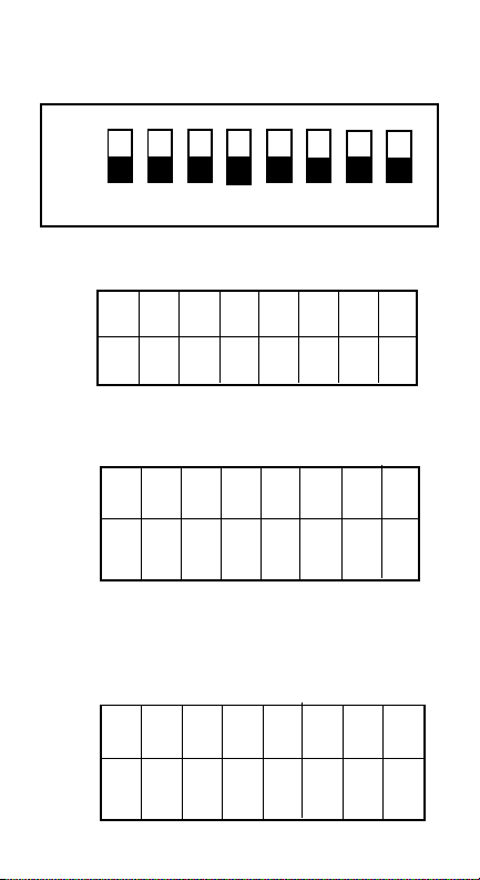
2. Set Dip switches 5, 6, 7, & 8 to the “ON” position, all
others to the “OFF” position.
3. Connect Transport unit w/head to power source -
either host machine, or adaptive power supply.
4. Listen for activation of transport motor - forward and
reverse for up to 2 seconds, then stop - READY.
5. After inserting the calibration paper, black paper first, the
unit will carry the paper forward/
reverse several times. When the
process is complete, the unit will
return the paper.
6. Wait a few moments to allow for
complete transfer of calibration data to be stored in
memory. This is indicated via the LED on the test
harness, or the bezel light on some applications with fast
blinks.
7. Unsuccessful Calibrations - Check the lenses. Re-try
calibration. If necessary, refer to Error Conditions Chart
on the next page. Additional testing/troubleshooting may
be required.
Part #501-000032
Calibration sets a starting reference point for all optical
sensors within the unit. This can be done at the host unit or
at the work bench with just a power source.
When to Calibrate
Note: When installing a new CPU, you must recalibrate.

Auto-Calibration
Error Conditions Chart
Look at the indicator LED connected to the test
harness, or the bezel light. If the LED blinks from 1 to
11 times at 1/2 second intervals, an error exists.
Count the number of blinks and match with the list
below. If you missed the count, it will repeat after a 1-
second pause.
# of
Blinks Error Found During Calibration
1
2
3
4
5
6
7
8
9
10
11
Entrance Lever Error
Solenoid Error
Entrance Sensor Error
Transport Jam
Gain Error - White or Black Level
Digital/Analog Error
Bar Code Sensor Error
Acceptor Head Error
Magnetic Setting Error
Write-in Error
Black Level Error

WBATM - In Field
Stand-Alone Test Mode
Accomplish this function by applying power to the unit’s
Transport and Head only.
Note: Perform this test outside the game using an
extension harness, or power supply hook-up.
• Remove power.
• Prior to starting, set the Dip switches. Place Dip switches
1,2,3 & 8 in the “ON” position.
• Apply power.
• Turn Dip switch 8 “OFF.” The unit should cycle briefly.
• The unit is now ready for the test.
• Insert a known bill/note.
• The bill/note will either go completely through, or be
rejected.
• If it rejects, check calibration. Re-calibrate if necessary.
If the unit still rejects, there is a possible sensor problem,
or incorrect software version. Go to “Bill Return Tests”
page.
• If it does not take the bill/note in, check for power.
Note: While in this test mode, you can verify if the unit is
working properly.
• When the unit cycles on power up, this indicates power
and forward motor operation.
• When you insert a plain piece of paper and it is rejected,
this indicates reverse motor operation.
• When you insert various denominations of bills, and they
are accepted, this indicates the bill was successfully
matched against the characteristics of the software.

(Continued )
WBATM - DT-004 Downloading
Using the JCM DT-004 Download Tool
DO NOT USE the 2-pin connector for power input.
This is output power and can damage the DT-004.
1. Make sure power is applied to the DT-004 via a 3-pin connector
from the PS15-007 power supply with the adaptive harness, Part
No. 400-100067, or the power supply harness connection in the
game.
2. With the power “OFF”, be sure the 4MEG Program EPROM is
installed properly.
3. Dip switches on WBA:
Set Dip switches 6, 7, and 8 to the “ON” position, and all others to
the “Off” position.
4. Harnessing
•For WBA-10/20: Use Part No. 400-10068 (Power from game to
DT-004), Part No. 400-100069 (Data from DT-004 to WBA
unit).
Note: The PS15-007 can be used to substitute for a power source
instead of using the harness, Part No. 400-100068 at the game.
When there is an RS-232 board, disconnect the board and use
the harness, Part No. 400-100042 in conjunction with harness,
Part No. 400-100069
•For WBA-12/22: Use Part No. 400-100070 (Power from game
to DT-004), Part No. 400-100071 (Data from DT-004 to WBA
unit).
Note: The PS15-007 can be used to substitute for a power source
instead of using the harness, Part No. 400-100070 at the game.
When there is an RS-232 board, the WBA-12/22 can be flashed
through the RS-232 board using the harness, Part No. 400-
100071.
5. Turn the power switch on the DT-004 to the “ON” position. The
Power LED should light.
6. Verify the LEDs on the WBA CPU board are illuminated, and are
blinking back and forth. This indicates download mode.

WBATM - DT-004 Downloading
(con’t)
8. While downloading, the download status LEDs on the DT-004
will illuminate, indicating status of the download.
7. To begin the download process, press the “START” button. The
“RDY” LED will begin to blink.
9. When the downloading is complete, the “OK” LED will light
and a buzzer will sound for about a second.
10.Press the “RESET” button once, then press the “VERIFY”
button once. After approximately 10 seconds, a buzzer will sound
for about a second, and the “OK” LED will illuminate.
11.Turn power on the DT-004 to the “OFF” position, remove the
harness connectors from the unit, and return the Dip switches to
their normal operating positions.
12.To repeat the process with other units, follow these instructions from
#3 through #10.
NOTE: After downloading/upgrading, recalibrate the units using the
calibration/reference paper, Part No. 501-00032 to ensure proper
operation.

Examples of ID Interface Usage
This is an example of the various usages for JCM interfaces
WBA - I/F
ID Interface OEM (Gaming Manufacturer)
ID-044C/0C3 Aristocrat
ID-003 JCM Standard: Aristocrat, Atronics,
Bally, CDS, Sigma, VLC, and WMS
ID-022/023 IGT: S-Slots, P.E., P.E. Plus
ID-024 IGT: Game King, I-Game, and
Vision Series
DBV - I/F
ID Interface OEM (Gaming Manufacturer)
ID-004/Bar JCM Standard: CDS and VLC
ID-011/015 Sigma and Videotronic
ID-022/023 IGT: S-Slots, P.E., P.E. Plus
ID-024 IGT: Game King, I-Game, and Vision Series
ID-044P/045P Bally
ID-044/045W WMS

JCM American Corp.
Regional Offices
Western Region: Main
925 Pilot Road
Las Vegas, NV 89119
(800) 683-7248 Office (702) 651-0000
Fax (702) 651-0214
Mid-Western Region
3000 Dundee Road, Ste. #402
Northbrook, IL 60062
Office (847) 418-3354 Fax (847) 418-3357
Eastern Region
3 Canale Drive, Ste. #4
Egg Harbor, NJ 08234
Office (609) 677-8909 Fax (609) 677-8820
Southern Region
4063 Ginger Dr., Ste. B
Biloxi, MS 39532
Office (228) 354-8600 Fax (228) 354-8608
WBA Quick Reference
Manual
Part No. 960-0000272001 JCM American, Corp.
This manual suits for next models
4
Table of contents
Other JCM Banknote Counter manuals
Popular Banknote Counter manuals by other brands

Ribao
Ribao BCS-160 user manual

tbs electronics
tbs electronics SD-900 One user manual

CashConcepts
CashConcepts CCE 4000 Short manual

PRO Intellect Technology
PRO Intellect Technology PRO 15 user manual

Double Power Electronics
Double Power Electronics DP-8120VB user manual

Olympia
Olympia NC 455 operating manual