Jct JES-301E1/V User manual

Date / Stand 07/22
Heated Sample Probe
Beheizte Gasentnahmesonde
OPERATING
MANUAL
BEDIENUNGS-
ANLEITUNG
OPERATING
MANUAL
BEDIENUNGS-
ANLEITUNG
JES-301E1/V
JES-301E1OS/V

Inhalt Table of Content
Manual JES-360Ex
BA_DE_JES301E1_E1OS_v4.0 ––––––––––––––– [ 2 / 44 ] –––––––––––––––––
Manual JES-301E1/V & JES-301E1OS/V
1. Introduction 3
1.1. Information about this operating manual 3
1.2. Explanation of symbols 3
1.3. General safety information 3
1.4. Intended use 4
1.5. Storage 4
1.6. Staff qualification 4
1.7. Description of device 5
1.8. Upgrade Options 5
2. Order codes 7
3. Technical data 12
3.1. Heater type table JHBEX 14
3.2. Modular and versatile 14
3.3. Service and security 14
3.4. Pressure curve 15
3.5. Gas flow diagram 15
3.6. Pressure-temperature curve process shut-off valve 15
4. Installation, visual inspection 16
5. Installation instructions 16
5.1. Mounting 16
5.2. Electrical connections 19
5.3. Terminal strip 20
6. Start up 20
7. Maintenance and service 21
7.1. Replacement of filter element 22
8. Demounting 23
9. Information about variants 24
9.1. Pneumatic actuator process shut-off valve 24
9.2. Air accumulator 24
10. Fault diagnostic check list 24
11. Dimensions JES-301E1/OS 25
12. Dimensions JES-301E1V/OSV 26
13. Spare parts 27
14. Certificates PTC heater element 31
15. Certificates junction box 8118 36
16. Certificates junction box 8146 39
1. Einleitung 3
1.1. Informationen zu dieser Bedienungsanleitung 3
1.2. Zeichenerklärung 3
1.3. Allgemeine Sicherheitsinformation 3
1.4. Bestimmungsmäßige Verwendung 4
1.5. Lagerung 4
1.6. Qualifikation des Personals 4
1.7. Produktbeschreibung 5
1.8. Erweiterungsoptionen 5
2. Bestellcodes 7
3. Technische Daten 12
3.1. Heizung Typentabelle JHBEX 14
3.2. Modular und vielseitig 14
3.3. Service und Sicherheit 14
3.4. Druckverlauf 15
3.5. Gasfluss Diagramm 15
3.6. Druck-Temperatur Verlauf Prozessabsperrventil 15
4. Installation, Sichtkontrolle 16
5. Installationsvorschriften 16
5.1. Montage 16
5.2. Elektrischer Anschluss 19
5.3. Klemmleiste 20
6. Inbetriebnahme 20
7. Wartung und Service 21
7.1. Austausch des Filterelementes 22
8. Demontage 23
9. Informationen zu den Varianten 24
9.1. Pneumatischer Aktuator für Prozessabsperrventil 24
9.2. Puffertank 24
10. Fehlerdiagnose Checkliste 24
11. Abmessungen JES-301E1/OS 25
12. Abmessungen JES-301E1V/OSV 26
13. Ersatzteile 27
14. Zertifikate PTC Heizelement 31
15. Zertifikate Klemmenkasten 8118 36
16. Zertifikate Klemmenkasten 8146 39
© 2022 JCT Analysentechnik GmbH
Reproduktion im Ganzen oder auszugsweise ohne vorherige
schriftliche Genehmigung verboten.
Alle verwendeten Markenzeichen sind Eigentum der entspre-
chenden Rechteinhaber.
JCT bietet diese Bedienungsanleitung “wie vorliegend" ohne
jede Garantie in irgendeiner Art, weder ausdrücklich noch still-
schweigend, einschließlich Garantien oder Bedingungen der
Marktgängigkeit oder Eignung für einen bestimmten Zweck.
Technische Änderungen vorbehalten.
© 2022 by JCT Analysentechnik GmbH
Reproduction in whole or in part in any form or medium without
written permission is prohibited
All trademarks not explicitly mentioned are property of their
legal owners.
JCT provides this operating manual "as is" without any warranty
of any kind, either express or implied, including warranties or
conditions of merchantability or fitness for a particular purpose.
Subject to technical modifications without notice.

Manual JES-360Ex
BA_DE_JES301E1_E1OS_v4.0 ––––––––––––––– [ 3 / 44 ] –––––––––––––––––
Manual JES-301E1/V & JES-301E1OS/V
Einleitung1.
Informationen zu dieser Bedienungsanleitung1.1.
Vielen Dank, dass Sie sich für unser Produkt
entschieden haben. Vor Inbetriebnahme die Sicherheits-
hinweise und die gesamte Bedienungsanleitung lesen.
Beachten Sie Warnungen auf Gerät und Bedienungsan-
leitung.
Bewahren Sie die Bedienungsanleitung immer in Reich-
weite auf. Bei Verkauf oder Weitergabe des Gerätes, ist
diese Bedienungsanleitung weiterzugeben, da sie ein
wesentlicher Bestandteil des Produktes ist.
Zeichenerklärung1.2.
Ist ein Textabschnitt mit einem der nachfolgenden
Warnsymbole gekennzeichnet, muss die im Text
beschriebene Gefahr vermieden werden, um möglichen
Konsequenzen vorzubeugen.
Allgemeine Sicherheitsinformation1.3.
Gasentnahmesonden sind hochentwickelte Geräte, die
nur von qualifiziertem Personal verbaut und bedient
werden dürfen. Es ist notwendig, dass diese
Bedienungsanleitung vor Installation oder Wartung, ge-
lesen und verstanden wird. Die Bedienung des Gerätes
hat ebenso unter Berücksichtigung der jeweils vor Ort
geltenden Sicherheitsbestimmungen und
Unfallverhütungsvorschriften zu erfolgen.
Eine Nichtbeachtung kann zu Sach- und/oder Personen-
Introduction1.
Information about this operating manual1.1.
Thank you for choosing our product. Before
commissioning, read the safety instructions and the
entire operating manual carefully. Observe the warnings
on the appliance and in the operating manual.
Always keep the operating manual within easy reach. If
you sell or pass on the device, be sure to hand over the
operating manual as well, as it is an essential part of the
device.
Explanation of symbols1.2.
If a section of text is marked with one of the following
warning symbols, the danger described in the text must
be avoided in order to prevent possible consequences.
General safety information1.3.
Sample probes are advanced devices that may only be
installed and operated by qualified personnel. It is
essential that this operating manual is read and
understood by those who install, use or maintain this
device. The appliance must also be handled in
compliance with the applicable local safety regulations
and accident prevention rules.
Non-observance may lead to material damage and/or
personal injury.
GEFAHR
weist auf eine gefährliche Situation hin, die,
wenn sie nicht vermieden wird, zum Tod oder
zu schweren Verletzungen führen kann.
WARNUNG
weist auf eine gefährliche Situation hin, die,
wenn sie nicht vermieden wird, zum Tod oder
zu schweren Verletzungen führen kann.
WARNUNG
Gefahr durch Stromschlag
WARNUNG
Gefahr durch Verbrennung
VORSICHT
weist auf eine gefährliche Situation hin, die,
wenn sie nicht vermieden wird, zu leichten
oder mittelschweren Verletzungen führen
kann.
Ex
weist auf besondere Bedingungen und/oder
Vorkehrungen hin.
HINWEIS
Weiterführende Informationen für den
Gebrauch des Gerätes.
DANGER
indicates a hazardous situation which, if not
avoided, could result in death or serious
injury.
WARNING
indicates a hazardous situation which, if not
avoided, could result in death or serious
injury.
WARNING
danger due to electric shock
WARNUNG
danger due to burning
CAUTION
indicates a hazardous situation which, if not
avoided, could result in minor or moderate
injury.
Ex
indicates special conditions and/or precauti-
ons.
NOTICE
Additional information on using the appliance

BA_DE_JES301E1_E1OS_v4.0 ––––––––––––––– [ 4 / 44 ] –––––––––––––––––
Manual JES-301E1/V & JES-301E1OS/V
JCT does not accept any liability for failure to observe the
safety devices and (warning) instructions listed in this
operating manual. This applies to installation,
operation and maintenance, even if not expressly
referred to in this operating manual. JCT is not
responsible for arbitrary changes on the device or for
inappropriate operation or use. If it can be assumed that
safe operation of the device is no longer possible, it must
be taken out of operation and secured against
unintentional operation.
Safe operation is no longer ensured in case:
the device is visibly damaged•
the device no longer functions•
of incorrect storage under inappropriate conditions•
the device has been subject to frequent moving•
Intended use1.4.
The devices are designed for use in gas analysis
systems only. Please observe the technical specifica-
tions regarding ambient and supply conditions and
admissible pressure and temperature limits.
Ex
Devices in hazardous areas may only be operated under
atmospheric conditions.
Storage1.5.
The device can be stored permanently under dry
conditions between -20 °C and 60 °C.
Staff qualification1.6.
For the activities described in this operating manual, a
suitably qualified specialist is required. This applies in
particular for work in the following areas
Product selection, configuration and modification•
Assembly, disassembly and storage of the appliance•
Installation•
Start up•
Maintenance, cleaning and service•
Professionals executing these tasks must have a level
of knowledge that includes relevant national standards
and regulations.
For operation in hazardous areas, further knowledge is
required; a level of knowledge described in the following
standards is recommended:
IEC/EN 60079-0, IEC/EN 60079-14, IEC/EN 60079-17,
IEC/EN 60079-19
schäden führen.
JCT übernimmt keine Haftung bei Nichtbeachtung der
Sicherheitsvorrichtungen und der in dieser
Bedienungsanleitung aufgeführten (Warn-)hinweise.
Dies gilt sowohl bei Installation, Betrieb als auch
Wartung. Auch dann, wenn in dieser Bedienungsanlei-
tung nicht ausdrücklich darauf hingewiesen wird. JCT
haftet nicht für eigenmächtige Veränderungen am Gerät
sowie für unsachgemäße Bedienung oder Verwendung.
Wenn anzunehmen ist, dass ein gefahrloser Betrieb
nicht möglich ist, muss dieses außer Betrieb gesetzt und
gegen unbeabsichtigten Betrieb gesichert werden.
Ein gefahrloser Betrieb ist nicht mehr gegeben,
wenn das Gerät sichtbare Beschädigungen aufweist•
wenn das Gerät nicht mehr arbeitet•
nach Lagerung unter ungünstigen Verhältnissen•
nach Transportbeanspruchungen•
Bestimmungsmäßige Verwendung1.4.
Die Geräte sind nur für den Einsatz in Gasanalysen-
systemen bestimmt. Bitte beachten Sie die Angaben in
den technischen Spezifikationen hinsichtlich Umge-
bungs- und Versorgungsbedingungen sowie zulässige
Druck- und Temperaturgrenzen.
Ex
Geräte in Ex Bereichen dürfen nur unter atmosphäri-
schen Bedingungen betrieben werden.
Lagerung1.5.
Das Gerät kann dauerhaft unter trockenen Bedingungen
zwischen -20 °C und 60 °C gelagert werden.
Qualifikation des Personals1.6.
Für die in dieser Bedienungsanleitung beschriebenen
Tätigkeiten ist eine entsprechend qualifizierte Fachkraft
erforderlich. Dies gilt vor allem für Arbeiten in den
Bereichen
Produktauswahl, Konfiguration und Modifikation
•
Montage, Demontage und Lagerung des Gerätes•
Installation•
Inbetriebnahme•
Wartung, Reinigung und Service•
Fachkräfte, die diese Tätigkeiten ausführen, müssen
einen Kenntnisstand haben, der relevante nationale
Normen und Bestimmungen umfasst.
Für Tätigkeiten in explosionsgefährdeten Bereichen sind
weitere Kenntnisse erforderlich; empfohlen wird ein
Kenntnisstand der in folgenden Normen beschrieben ist:
IEC/EN 60079-0, IEC/EN 60079-14, IEC/EN 60079-17,
IEC/EN 60079-19

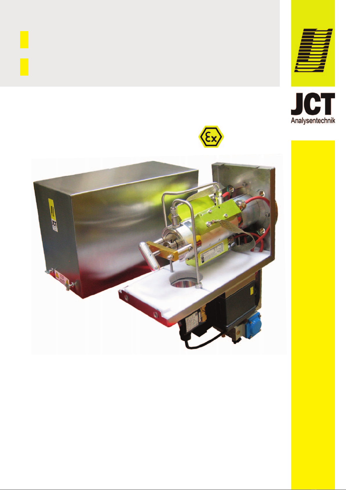
Description of device1.7.
The heated sample probe is used for continuous
sampling of gases containing dust and aerosols in
extractive analyzer systems. Water vapor and high
corrosive gases must be kept above their dew point to
prevent corrosion and sample degradation prior to
analysis or sample conditioning.
The sample probe is available in many different versions
to meet a wide variety of requirements.
The JES-301E1 & E1OS can be equipped with different
large-area, replaceable heated filter elements. The filter
element is mounted in an electrically heated stainless
steel housing covered by a thermally insulated weather
protection enclosure. The model series JES-301E1 &
E1OS is built to be equipped with various valves. The
sample probes can be built for different
temperature classes T3/T4. The temperature is
regulated by a maintenance free, self regulating PTC
heater elements with low temperature alarm. The heated
sample line JHX series is directly connected with a
moveable PG 42 cable conduit on the weather protection
enclosure. A universal mounting clamp is available to
connect other types of heated sample lines. For a correct
and optimal selection of various sample pipe
constructions and materials, our trained staff will be
pleased to assist you.
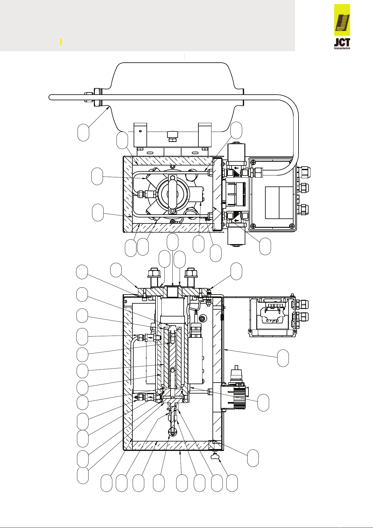
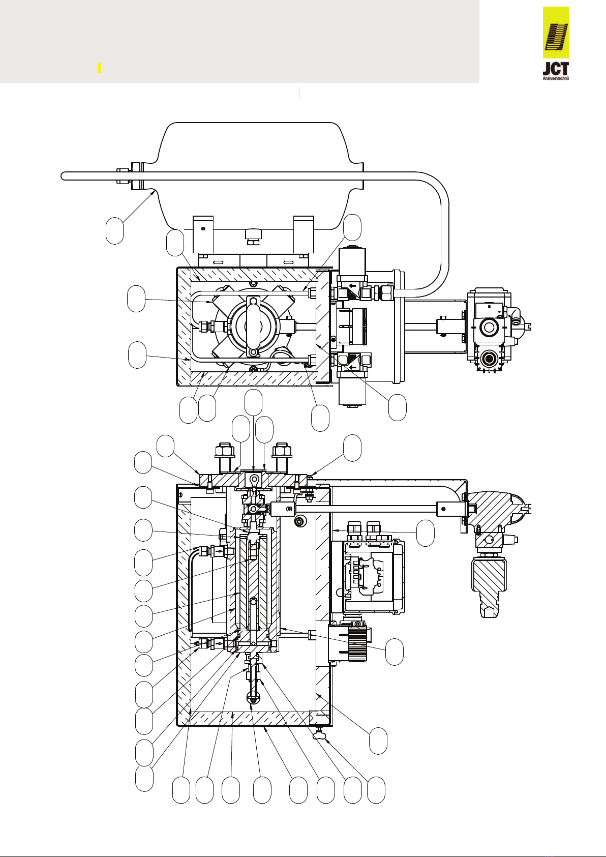
The sample probe consists of the heated filter head, Ex
heater, mounting flange, valves and mounting material,
which can be mounted horizontally or vertically. The
sample probe´s is mounted directly to a standard
process flange.
Upgrade Options1.8.
With additional modules you may put together sample
probes according to most diverse requirements.
Upgrade options are factory-made product adaptations
which in most cases cannot be carried out by the
customer or on site.(Refer to chapter 13 for the technical
data)
Filter elements of various materials
Ceramic•
Glass fiber•
Stainless steel•
Pyrex wool•
Surface coated filter element1.8.1.
The surface coated 0,2 µm filter element restrains the
sedimentation of dust and dirt on the filter surface.
Produktbeschreibung1.7.
Die beheizte Gasentnahmesonde dient zur
kontinuierlichen Entnahme von staub- und aerosol-
haltigen Gasen bei extraktiven Analysensystemen.
Wasserdampf und hohe korrosive Gasfeuchte müssen
über dem Taupunkt gehalten werden, damit keine
Veränderung des Gases vor den Analysengeräten oder
der Probenaufbereitung stattfinden kann.
Die Gasentnahmesonde ist in vielen unterschiedlichen
Konfigurationen lieferbar, um unterschiedlichsten
Anforderungen gerecht zu werden.
Die JES-301E1 & E1OS ist mit unterschiedlichen
großflächigen, austauschbaren beheizten Filterelement
ausstattbar. Das Filterelement ist in einem elektrisch
beheizten Edelstahlgehäuse montiert und zusätzlich in
einem thermisch isolierten Wetterschutzgehäuse unter-
gebracht. Die JES-301E1 & E1OS Modellreihe kann mit
verschiedenen Ventilen ausgestattet werden. Die
Gasentnahmesonde kann für unterschiedliche
Temperaturklassen T3/T4 gebaut werden. Die
Temperaturregelung erfolgt durch eine wartungsfreie,
selbstregelnde PTC Heizung mit Alarmmeldung für
Untertemperatur. Die beheizte Messgasleitung der Serie
JHX wird direkt am Wetterschutzgehäuse der
Gasentnahmesonde über eine verschiebbare PG 42
Verschraubung montiert. Für die Montage anderer
Messgasleitungsstypen steht eine Montageschelle zur
Verfügung. Für eine korrekte und optimale Auswahl der
verschiedenen Entnahmerohre und Materialien steht
Ihnen unser geschultes Personal gerne zur Seite.
Die Gasentnahmesonde besteht aus dem beheiztem
Filterkopf, Ex Heizer, Montageflansch, Ventilen und
Montagematerial. Sie kann horizontal oder vertikal
montiert werden. Die Gasentnahmesonde wird direkt an
einem Standard-Prozessflansch montiert.
Erweiterungsoptionen1.8.
Mit zusätzlichen Modulen lassen sich die Gasentnahme-
sonden genau an unterschiedlichste Anforderungen
anpassen: Upgrade Optionen sind werksseitig
durchgeführte Produktanpassungen welche in den meis-
ten Fällen weder kundenseitig noch vor Ort durchgeführt
werden können. (Technische Daten dazu finden Sie in
Kapitel 13)
Filterelemente aus verschiedenen Materialien
Keramik•
Glasfaser•
Edelstahl•
Glaswolle•
Oberflächenbeschichtetes Filterelement1.8.1.
Das oberflächenbeschichtete 0,2 µm Filterelement
erschwert die Ablagerung von Staub- und Schmutz-
partikeln am Filterelement.
BA_DE_JES301E1_E1OS_v4.0 ––––––––––––––– [ 5 / 44 ] –––––––––––––––––
Manual JES-301E1/V & JES-301E1OS/V

Additional heater elements1.8.2.
Additional heater elements make the sample probe
suitable also for very low ambient temperatures.
Heater for T4 temperature class1.8.3.
Heating for temperature class T4 with one or more
heater elements depending on the ambient temperature.
Process shut-off valve1.8.4.
The sample probes can be equipped with a process
shut-off ball valve to shut-off the gas flow on the process
side.
The process shut-off valve is controlled manually,
pneumatically or electrically.
Back purge port for sample probe filter1.8.5.
Periodical back purging of the filter element with
instrument air, combined with a surface coated filter
element, improves the operating life additionally. It is
recommended for small particles exceeding 500 mg/m³
(e.g. in cement industry) and for large particles
exceeding 1000 mg/m³.
Calibration gas port1.8.6.
The calibration gas port allows calibration on the raw gas
side with minimum effort.
Back purge control valves and reduction valves1.8.7.
Directly on the sample probe mounted back purge
control valves with a large passage opening allow
efficient back purge results with compact design. These
valves are available in several coil voltages.
To reduce the pressure shocks occurring during the back
purge of the sample gas output, the pressure
reduction valve JBPRV can be integrated into the
sample outlet.
Actuators and pilot valves for process shut-off1.8.8.
valves
Versions of the sample probes with shut-off on the
process side are equipped with a full-bore size ball valve
which can be operated manually, pneumatically or
electrically. A pilot valve on the actuator can also be
installed for pneumatic control. A back purge control can
be integrated into the sample probe for the entire control
sequence from process shutdown and back purge.
Zusätzliche Heizelemente1.8.2.
Zusätzliche Heizelemente machen die Gasentnahme-
sonde auch für sehr niedrige Umgebungstemperaturen
geeignet.
Heizer für Temperaturklasse T41.8.3.
Beheizungsausführung für Temperaturklasse T4 mit
einem oder mehreren Heizelementen je nach
Umgebungstemperatur.
Prozessabsperrventil1.8.4.
Die Gasentnahmesonden können mit einem Absperr-
kugelhahn zur prozessseitigen Absperrung des
Gasflusses ausgestattet werden.
Die Steuerung des Ventils kann manuell, pneumatisch
oder elektrisch erfolgen.
Anschluss für Sondenfilter Rückspülung1.8.5.
Eine periodische Rückspülung des Filterelements mit
Instrumentenluft, in Kombination mit dem oberflächen-
beschichteten Filterelement, erhöht die Standzeit
zusätzlich. Sie wird bei kleinen Partikeln ab 500 mg/m³
(z.B. in der Zementindustrie) und bei größeren Partikeln
ab 1000 mg/m³ empfohlen.
Kalibriergasanschluss1.8.6.
Ein Kalibriergasanschluss ermöglicht eine rohgasseitige
Kalibrierung mit minimalem Aufwand.
Rückspül-Steuerventile und Reduktionsventile1.8.7.
Direkt an der Gasentnahmesonde angebaute Rückspül-
Steuerventile mit großer Durchgangsöffnung
ermöglichen effiziente Rückspülergebnisse bei kompak-
ter Bauweise. Diese Ventile stehen in mehreren
Spulenspannungen zur Verfügung.
Zur Reduzierung, von bei der Rückspülung auftretenden
Druckstößen am Messgas Ausgang, kommt das in der
Anschlussverschraubung integrierte Druckminderventil
JBPRV zum Einsatz.
Steuerungen und Pilotventile für Prozessab-1.8.8.
sperrventil
Ausführungen der Gasentnahmesonden mit prozess-
seitiger Absperrung sind mit einem Volldurchgangs-
Kugelhahn ausgestattet welcher manuell, pneumatisch
oder elektrisch betätigt werden kann. Für pneumatische
Ansteuerung kann ein Pilotventil am Aktuator
angebracht werden. Für den gesamten Steuerungsab-
lauf von der Prozessabsperrung und Back Purge kann
eine Rückspülsteuerung in der Gasentnahmesonde
integriert werden.
BA_DE_JES301E1_E1OS_v4.0 ––––––––––––––– [ 6 / 44 ] –––––––––––––––––
Manual JES-301E1/V & JES-301E1OS/V

Air accumulator1.8.9.
Unheated air accumulators with a volume of two or five
liters are available for back purge.
GPR-ATEX instrument enclosure1.8.10.
Antistatically coated protective boxes according to
EN60079-0 for outdoor applications with high thermal
load.
Order codes2.
Scope of delivery: device, mounting material, gasket for
flange, gasket for sampling pipe, operating manual.
JES-301E1S without process shut-off valve
JES-301E1SV with process shut-off valve
*1...with non-return valve
Puffertank1.8.9.
Zur Versorgung der Rückspülung stehen unbeheizte
Puffertanks mit zwei oder fünf Liter Volumen zur
Verfügung.
GRP-ATEX Schutzkasten1.8.10.
Antistatisch beschichtete Schutzkästen nach
EN60079-0 für thermisch stark beanspruchte
Applikationen im Außenbereich.
Bestellcodes2.
Lieferumfang: Gerät, Montagematerial, Flanschdichtung,
Dichtung für Entnahmerohr, Bedienungsanleitung.
JES-301E1S ohne Prozessabsperrventil
JES-301E1SV mit Prozessabsperrventil
*1...mit Rückschlagventil
BA_DE_JES301E1_E1OS_v4.0 ––––––––––––––– [ 7 / 44 ] –––––––––––––––––
Manual JES-301E1/V & JES-301E1OS/V
Filterelement /
filter element
Optionen /
options
Montagflansch /
mounting flange
Anschlussspannung /
power supply Ex Zone
Art.Nr. /
part no. Modell / model
beheizt auf 120 °C
2µm Keramik
2 µm ceramic
0,2µm Keramik beschichtet
0,2 µm ceramic coated
Anschluss für Rückspülung *1
Back purge port *1
Kalibriergas Anschluss *1
Calibration port *1
DN65/PN6
2" ANSI
115 - 230 VAC 50/60Hz
Ex Zone 1, 2, 21 o(de)r 22
35.00400 JES-301E1S X X X X X
35.00402 JES-301E1BS X X X X X X
35.00404 JES-301E1CS X X X X X X
35.00406 JES-301E1BCS X X X X X X X
35.00442 JES-301E1SZ X X X X X
35.00433 JES-301E1BSZ X X X X X X
35.00427 JES-301E1CSZ X X X X X X
35.00421 JES-301E1BCSZ X X X X X X X
Filterelement /
filter element
Optionen /
options
Montagflansch /
mounting flange
Anschlussspannung /
power supply
Ex
Zone
Art.Nr. /
part no. Modell / model
beheizt auf 120 °C
heated to 120 °C
2µm Keramik
2 µm ceramic
0,2µm Keramik beschichtet
0,2 µm ceramic coated
Anschluss für Rückspülung
*1
Kalibriergas Anschluss *1
Calibration port *1
Prozessabsperrventil
Process shut-off valve
DN65/PN6
2" ANSI
115 - 230 VAC 50/60Hz
Ex Zone 1, 2, 21 o(de)r 22
35.00439 JES-301E1SV X X X X X X
35.00440 JES-301E1BSV X X X X X X X
35.00441 JES-301E1CSV X X X X X X X
35.00443 JES-301E1BCSV X X X X X X X X
35.00412 JES-301E1SVZ X X X X X X
35.00424 JES-301E1BSVZ X X X X X X X
35.00444 JES-301E1CSVZ X X X X X X X
35.00445 JES-301E1BCSVZ X X X X X X X X

JES-301E1OS without process shut-off valve
JES-301E1OSV with process shut-off valve
*1...with non-return valve
JES-301E1OS ohne Prozessabsperrventil
JES-301E1OSV mit Prozessabsperrventil
*1...mit Rückschlagventil
BA_DE_JES301E1_E1OS_v4.0 ––––––––––––––– [ 8 / 44 ] –––––––––––––––––
Manual JES-301E1/V & JES-301E1OS/V
Filterelement /
filter element
Optionen /
options
Montageflansch /
mounting flange
Anschlussspannung /
power supply Ex Zone
Art.Nr. /
part no. Modell / model
beheizt auf 120 °C
2µm Keramik
2 µm ceramic
0,2µm Keramik beschichtet
0,2 µm ceramic coated
Anschluss für Rückspülung *1
Back purge port *1
Kalibriergas Anschluss *1
Calibration port *1
DN65/PN6
2" ANSI
115 - 230 VAC 50/60Hz
Ex Zone 1, 2, 21 o(de)r 22
35.00401 JES-301E1OS X X X X X
35.00403 JES-301E1BOS X X X X X X
35.00415 JES-301E1COS X X X X X X
35.00407 JES-301E1BCOS X X X X X X X
35.00413 JES-301E1OSZ X X X X X
35.00405 JES-301E1BOSZ X X X X X X
35.00417 JES-301E1COSZ X X X X X X
35.00419 JES-301E1BCOSZ X X X X X X X
Filterelement /
filter element
Optionen /
options
Montageflansch /
mounting flange
Anschlussspannung /
power supply Ex Zone
Art.Nr. /
part no. Modell / model
beheizt auf 120 °C
heated to 120 °C
2µm Keramik
2 µm ceramic
0,2µm Keramik beschichtet
0,2 µm ceramic coated
Anschluss für Rückspülung *1
Back purge port *1
Kalibriergas Anschluss *1
Calibration port *1
Prozessabsperrventil
Process shut-off valve
DN65/PN6
2" ANSI
115 - 230 VAC 50/60Hz
Ex Zone 1, 2, 21 o(de)r 22
35.00426 JES-301E1OSV X X X X X X
35.00434 JES-301E1BOSV X X X X X X X
35.00435 JES-301E1COSV X X X X X X X
35.00431 JES-301E1BCOSV X X X X X X X X
35.00436 JES-301E1OSVZ X X X X X X
35.00437 JES-301E1BOSVZ X X X X X X X
35.00438 JES-301E1COSVZ X X X X X X X
35.00430 JES-301E1BCOSVZ X X X X X X X X

JES-301E1S without process shut-off valve
JES-301E1S ohne Prozessabsperrventil
BA_DE_JES301E1_E1OS_v4.0 ––––––––––––––– [ 9 / 44 ] –––––––––––––––––
Manual JES-301E1/V & JES-301E1OS/V
21
15
13
10 12 11 47
35
30
55
48
1
2
53
27
7
48
47
56
8
79
54
17
22
25
25
25
25
25 25
25
26
26
45
30
30
Abbildung zeigt Upgradeoptionen
Illustration shows upgrade options

JES-301E1SV with process shut-off valve
JES-301E1SV mit Prozessabsperrventil
BA_DE_JES301E1_E1OS_v4.0 ––––––––––––––– [ 10 / 44 ] –––––––––––––––––
Manual JES-301E1/V & JES-301E1OS/V
21
15
13
10 12 11 47
35
30
55
48
1
2
53
27
7
48
47
56
8
79
54
17
22
25
25
25
25
25 25
25
26
26
45
30
Abbildung zeigt Upgradeoptionen
Illustration shows upgrade options

BA_DE_JES301E1_E1OS_v4.0 ––––––––––––––– [ 11 / 44 ] –––––––––––––––––
Manual JES-301E1/V & JES-301E1OS/V
1 Montageflansch
2 Gehäusedichtung
5 Mantel
6 Filterelementverschraubung
7 Filterelementdichtung
8 Filterelement
9Filterhalter Trägerelement
10 Filterhalter Dichtkolben
11 O-Ring B
12 O-Ring A
13 Abziehbolzen
15 Schwenkarm
17 Abziehvorrichtung
21 T-Griff
22 Alu Mantel
25 Wärmeisolation
26 Wetterschutzgehäuse
27 Erdungsanschluss
30 PTC Heizelement
35 Gehäuseverschluss
39 Kabelverschraubung Netzanschluss
43 Absperrkugelhahn
45 Messgas Eingang
46 Messgas Ausgang
47 Anschluss Rückspülung (optional)
48 Kalibriergasanschluss (optional)
49 Rückschlagventil
50 T-Griff für Absperrkugelhahn
53 Dichtung für Entnahmerohr
54 Flanschdichtung
1 Mounting flange
2 Enclosure gasket
5 Cylinder
6 Filter element screw
7 Filter element gasket
8 Filter element
9 Filter retainer
10 Filter tighting piston
11 O-ring B
12 O-ring A
13 Bolt
15 Pivoting frame
17 Extractor
21 T-handle
22 Aluminium cover
25 Thermal insulation
26 Weather protection enclosure
27 Ground connection
30 PTC heater element
35 Housing lock
39 Cable gland power supply
43 Process shut-off ball valve
45 Sample gas inlet
46 Sample gas outlet
47 Back purge port (option)
48 Calibration gas port (option)
49 Non-return valve
50 T-handle for process shut-off ball valve
53 Gasket for sample tube
54 Flange gasket

Technical data3.
NOTE
If upgrade options are part of the sample probe the
information of the chapter 13 applies additionally and
has priority in case of doubt.
Subject to change without notice
*1...Mounting material is included
Technische Daten3.
HINWEIS Sind in der Gasentnahmesonde
Erweiterungsoptionen verbaut, gelten zusätzlich und im
Zweifelsfall vorrangig die Informationen in Kapitel 13.
Technische Änderungen vorbehalten
*1...Montagematerial wird mitgeliefert
BA_DE_JES301E1_E1OS_v4.0 ––––––––––––––– [ 12 / 44 ] –––––––––––––––––
Manual JES-301E1/V & JES-301E1OS/V
Betriebsdaten
Temperatur max. 120 °C
Prozessdruck max. 2 bara
Durchfluss bis zu 600 Nl/h, applikations-
abhängig
Einbauwinkel empfohlen 5°bis 15° aus der
Horizontalen fallend
Aufheizzeit ca. 180 min
Einsatztemperatur 0 °C...55 °C
Zulässige
Umgebungstemperatur -10 °C...55 °C
Einbaulage Verdrehwinkel max. 45°
Durchfluss (Rückspülung) ca. 4 Nm3/h @ 4 bar,
5 Nm3/h @ 6 bar
Rückspülmedium Inertgas / Instrumentenluft
nur für Prozessabsperrventil (V)
Prozessabsperrventil Kugelhahn, Temp. max. 200
°C @ 7 bar
Sitzmaterial verstärktes PTFE
Konstruktion
Abmessungen über alles 168 x 415 x 316 mm BxHxT
Abmessungen
Klemmenkasten 115 x 115 x 64 mm BxHxT
Filterelement
2 µm Keramik oder 0,2 µm
Keramik oberflächenbe-
schichtet
Aktive Filteroberfläche 170 cm2
Montageflansch
DN 65, PN 6; Form A nach
EN 1092-1; 1.4401
oder 2“ ANSI Flansch; 150
lbs., nach ASME B16.5
Messgas Eingang G3/4“ Innengewinde
Messgas Ausgang 1/8“ NPT Innengewinde
Kalibriergasanschluss
(Option) 6 mm Rohrstutzen, 1.4401
Anschluss für Rückspülung
(Option) 6 mm Rohrstutzen, 1.4401
Mediumberührte Materialien 1.4404, Keramik, Viton®
Heizelement PTC, selbstlimitierend
Schutzart
Heizung: IP68
Gasentnahmesonde: IP43
Klemmenkasten IP66/67
Operational data
Temperature max. 120 °C
Operating pressure max. 2 bara
Flow rate up to 600 Nl/h, depending on
application
Mounting angle
range 5° to 15° with respect
to the horizontal, sloping
down
Heat up time approx. 180 min
Operating temperature range 0 °C...55 °C
Permissible
ambient temperature -10 °C...55 °C
Mounting position torsion angle max. 45°
Flow rate (back purge) approx. 4 Nm3/h @ 4 bar,
5 Nm3/h @ 6 bar
Back purge medium inert gas / instrument air
for process shut-off valve only (V)
Process shut-off valve ball valve, temp. max. 200 °C @
7 bar
Seat material reinforced PTFE
Construction
Dimensions over all 168 x 415 x 316 mm WxHxD
Dimensions
junction box 115 x 115 x 64 mm WxHxD
Filter element 2 µm ceramic or 0.2 µm
ceramic coated
Active filter surface 170 cm2
Mounting flange
DN 65, PN6; form A accor-
ding to EN 1092-1; SS316
or 2“ ANSI 150 lbs; accor-
ding to ASME B16.5
Sample gas inlet G3/4“ female thread
Sample gas outlet 1/8“ NPT female thread
Calibration gas port (option) pipe 6 mm, SS316
Back purge port (option) pipe 6 mm, SS316
Gas wetted materials SS316L, ceramic, Viton®
Heater element PTC, self limiting
Protection class
heater: IP68
sample probe: IP43
junction box: IP66/67

BA_DE_JES301E1_E1OS_v4.0 ––––––––––––––– [ 13 / 44 ] –––––––––––––––––
Manual JES-301E1/V & JES-301E1OS/V
Wetterschutzgehäuse 1.4301, wärmeisoliert, Farbe
Edelstahl natur
Gewicht
JES-301E1/E1OS
JES-301E1SV/E1OSV
ca. 11 kg
ca. 14,5 kg
Zündschutzart
Klemmenkasten
II 2G Ex em II T6/T5/T4
II 2D Ex tD A21 IP66 T80 °C,
T95 °C
Zündschutzart
Magnetventile
II 2G Ex mb IIC T4 Gb
II 2D Ex mb IIIC T130 °C Db
mb IIC T4 Gb
mb IIC T130 °C Db
Zündschutzart
Pilotventile
II 2G Ex h IICT6 Gb
II 2D Ex h IIIC T80 °C
ia IIC T6 Ga
tb IIIC T80 °C Db IP65
Zulassungen / Zeichen
Heizelement IECEx, ATEX, KCs, PESO
Zulassungen / Zeichen
Klemmenkasten
LCIE 02 ATEX 6240
IECEx PTB 06.0046
Zulassungen / Zeichen
Magnetventile
PTB 14ATEX 2023 X
IECEx PTB 14 0049X
Zulassungen / Zeichen
Pilotventile
IECEx PTB 13.0009
PTB 09 ATEX 2001
Elektrik
Anschlussspannung 115...230 VAC 50/60 Hz ±10 %
Magnetventile 24 VDC / 115 VAC / 230 VAC ±10%
Pilotventile 24 VDC / 115 VAC / 230 VAC ±10%
Leistungsaufnahme
(200 W pro Heizelement) 200...600 W
Einschaltstrom ca. 4 A 230 VAC
ca. 8 A 115 VAC
Einschaltdauer 100 %
Weather protection
enclosure
SS304, thermal insulated, colour
stainless steel natural
Weight
JES-301E1/E1OS
JES-301E1SV/E1OSV
approx. 11 kg
approx. 14.5 kg
Type of protection
junction box
II 2G Ex em II T6/T5/T4
II 2D Ex tD A21 IP66 T80 °C,
T95 °C
Type of protection
solenoid valves
II 2G Ex mb IIC T4 Gb
II 2D Ex mb IIIC T130 °C Db
mb IIC T4 Gb
mb IIC T130 °C Db
Type of protection
Pilot valves
II 2G Ex h IICT6 Gb
II 2D Ex h IIIC T80 °C
ia IIC T6 Ga
tb IIIC T80 °C Db IP65
Approval / Sign
heater element IECEx, ATEX, KCs, PESO
Approval / Sign
junction box
LCIE 02 ATEX 6240
IECEx PTB 06.0046
Approval / Sign
solenoid valves
PTB 14ATEX 2023 X
IECEx PTB 14 0049X
Approval / Sign
pilot valves
IECEx PTB 13.0009
PTB 09 ATEX 2001
Electric
Power supply 115...230 VAC 50/60 Hz ±10 %
Solenoid valves 24 VDC / 115 VAC / 230 VAC ±10%
Pilot valves 24 VDC / 115 VAC / 230 VAC ±10%
Power consumption
(200 W per heater) 200...600 W
Inrush current approx. 4 A 230 VAC
approx. 8 A 115 VAC
On-time 100 %
Low temperature contact Intrinsically safe
NAT=75 °C (NO @ AT)
Switching capacity contact
Effective internal capacitance
Effective internal inductance
max.120 VAC, 1A
min. 5 VDC/ 1 mA
Ci = 0.075 nF
Li = 0.049 µH
Cable entry supply M-cable gland 20 x 1.5 (black)
Cable entry status contact M-cable gland 16 x 1.5 (blue)
Electrical connection Spring type terminal
max 2.5 mm²
Fusing external, on installation site
Approval / Sign CE, EAC
Untertemperaturkontakt Eigensicher
NAT=75°C (NO @ UT)
Schaltvermögen Kontakt
Wirksame innere Kapazität
Wirksame innere Induktivität
max.120 VAC, 1A
min. 5 VDC/ 1 mA
Ci = 0,075 nF
Li = 0,049 µH
Kabeleingang Versorgung M-Verschraubung 20 x 1,5
(schwarz)
Kabeleingang Statuskontakt M-Verschraubung 16 x 1,5 (blau)
Elektrischer Anschluss Zugfederklemmen
max 2,5 mm²
Absicherung extern, bauseits
Zulassungen / Zeichen CE, EAC

Heater type table JHBEX3.1.
Modular and versatile3.2.
Different sample pipe materials, electrically heated
sample pipes and large pre-filters make the JES-301E1
& E1OS adaptable for different applications.
Service and security3.3.
A temperature status contact signalizes low temperature.
Filter replacement can be done easily without any tools
and without disconnecting the heated sample line.
Heizung Typentabelle JHBEX3.1.
Modular und vielseitig3.2.
Unterschiedliche Entnahmerohrmaterialien, elektrisch
beheizte Entnahmerohre und große Vorfilter machen die
JES-301E1 & E1OS anpassungsfähig für
verschiedenste Applikationen.
Service und Sicherheit3.3.
Ein Statuskontakt signalisiert Untertemperatur. Der
Filterwechsel kann ohne Werkzeug und ohne
Demontage der beheizten Messgasleitung durchgeführt
werden.
BA_DE_JES301E1_E1OS_v4.0 ––––––––––––––– [ 14 / 44 ] –––––––––––––––––
Manual JES-301E1/V & JES-301E1OS/V
JHBEX.
mounting
location /
Einbauort
effects** /
einwirkend
auf**
Temperature class /
Temperaturklasse
Ambient Temp. /
Umgebungstemp.
Marking of type of protection /
Kennzeichnung der Zündschutzart
3000 Zone 1 (21) Zone 0 (20) T2 / T 300 °C -60 °C...135 °C
II (1)2G Ex db [Ga] IIC T2 Gb BVS 20 ATEX E029 X
II (1)2D Ex tb [Da] IIIC T300 °C Db BVS 20 ATEX E029 X
Ex db [Ga] IIC T2 Gb IECEx BVS 20.0023X
Ex tb [Da] IIIC T300 °C Db IECEx BVS 20.0023X
2300 Zone 1 (21) Zone 0 (20) 230 °C (T2)/ T230 °C
T2C (NEC) -60 °C...135°C
II (1)2G Ex db [Ga] IIC 230 °C (T2) Gb BVS 20 ATEX E 029 X
II (1)2D Ex tb [Da] IIIC T230 °C Db Gb BVS 20 ATEX E 029 X
Ex db [Ga] IIC 230 °C (T2) Gb IECEx BVS 20.0023X
Ex tb [Da] IIIC T230 °C Db IECEx BVS 20.0023X
2000 Zone 1 (21) Zone 0 (20) T3 / T 200 °C -60 °C...150 °C
II (1)2G Ex db [Ga] IIC T3 Gb BVS 20 ATEX E 029 X
II (1)2D Ex tb [Da] IIIC T200 °C Db BVS 20 ATEX E 029 X
Ex db [Ga] IIC T3 Gb IECEx BVS 20.0023X
Ex tb [Da] IIIC T200 °C Db IECEx BVS 20.0023X
1350 Zone 1 (21) Zone 0 (20) T4 / T 135 °C -60 °C...100 °C
II (1)2G Ex db [Ga] IIC T4 Gb BVS 20 ATEX E 029 X
II (1)2D Ex tb [Da] IIIC T135 °C Db BVS 20 ATEX E 029X
Ex db [Ga] IIC T4 Gb IECEx BVS 20.0023X
2001 Zone 1 (21) Zone 1 (21) T3 / T 200 °C -60 °C...150 °C
II 2G Ex db IIC T3 Gb BVS 20 ATEX E 029 X
II 2D Ex tb IIIC T200 °C Db BVS 20 ATEX E 029 X
Ex db IIC T3 Gb IECEx BVS 20.0023X
Ex tb IIIC T200 °C Db IECEx BVS 20.0023X
1351 Zone 1 (21) Zone 1 (21) T4 / T 135 °C -60 °C...100 °C
II 2G Ex db IIC T4 Gb BVS 20 ATEX E 029 X
II 2D Ex tb IIIC T135°C Db BVS 20 ATEX E 029 X
Ex db IIC T4 Gb IECEx BVS 20.0023X
Ex tb IIIC T135 °C Db BVS 20.0023X
2302 Zone 2 (22) Zone 2 (22) 230 °C (T2)/ T230 °C
T2C (NEC) -60 °C...135 °C
II 3G Ex dc IIC 230 °C (T2) Gc BVS 20 ATEX E 034 X
II 3 D Ex tc IIIC T230 °C Dc BVS 20 ATEX E 034 X
Ex dc IIC 230 °C (T2) Gc IECEx BVS 20.0023X
Ex tc IIIC T230 °C Dc IECEx BVS 20.0023X
2002 Zone 2 (22) Zone 2 (22) T3 / T 200 °C -60 °C...150 °C
II 3 G Ex dc IIC T3 Gc BVS 20 ATEX E 034 X
II 3 D Ex tc IIIC T200 °C Dc BVS 20 ATEX E 034 X
Ex dc IIC T3 Gc IECEx BVS 20.0023X
1352 Zone 2 (22) Zone 2 (22) T4 / T 135 °C -60 °C...100 °C
III 3 G Ex dc IIC T4 Gc BVS 20 ATEX E 034 X
II 3 D Ex tc IIIC T135°C Dc BVS 20 ATEX E 034 X
Ex dc IIC T4 Gc IECEx BVS 20.0023X
Ex tc IIIC T135°C Dc IECEx BVS 20.0023X
effects**...intended for mounting on pipelines and vessels where zone 0/zone 20 prevails.
einwirkend auf**…vorgesehen für die Montage auf Rohrleitungen und Behältern, in denen Zone 0/Zone 20 vorherrscht

Pressure curve3.4.
(with new filter element)
Gas flow diagram3.5.
JES-301E1SV / JES-301E1OSV
*...not in all models included
Pressure-temperature curve process shut-off3.6.
valve
Druckverlauf3.4.
(bei neuem Filterelement)
Gasfluss Diagramm3.5.
JES-301E1 / JES-301E1OS
*...nicht bei allen Modellen vorhanden
Druck-Temperatur Verlauf Prozessabsperrventil3.6.
BA_DE_JES301E1_E1OS_v4.0 ––––––––––––––– [ 15 / 44 ] –––––––––––––––––
Manual JES-301E1/V & JES-301E1OS/V
0,00
20,00
40,00
60,00
80,00
100,00
0 400 600 800 1000 1200 1400 1600 1800
delta p [mbar]
Flow [l/h]
filter & air @ 20°C
2μFilter
0,2μFilter
IN
OUT
CAL (C)
*
*
PURGE (B)
(V)
IN
OUT
CAL
*
*
PURGE

Installation, visual inspection4.
Check device for any damage caused by shipping.
Obvious damage must be reported to the responsible
shipping company and the distributor immediately.
Check if instrument and other parts correspond to order.
Installation instructions5.
Disconnect mains before working on electrical part•
of appliance.
The device has to be connected and grounded•
according to the local rules and regulations.
The flange temperature must not exceed 200 °C.•
Otherwise a change of construction is necessary,
eg. use of a thermal spacer.
Please consider Ex temperature class!
Using the volt free status contact is highly•
recommended. This is the only way to assure safe
operation of the sample probe.
The sample probe must always be mounted with a•
minimum inclination of 5° towards the sample pipe.
This is necessary to prevent a possible backflow of
the condensate into the sample probe.
Mounting5.1.
Mount sample probe with gasket on the process•
flange.
Observe mounting angle according technical•
specification.
Insert and fix mounting clamp in mounting hole for•
sample line.
Mount 1/8“ NPT male connector at sample gas•
outlet.
Attach heated sample line on weather protection•
enclosure with moveable PG 42 cable conduit or
mounting clamp. Connect the heated sample line
with the connector fitting gas-tight.
PG 42 Mounting clamp
NOTICE
The heated sample line must be strain relieved and must
not be hung on the fitting.
CAUTION
Never use grease when mounting the sample pipe!
Ex
In the event of a lightning strike hazard, surge protectors
must be installed.
Installation, Sichtkontrolle4.
Überprüfen Sie das Gerät auf eventuelle Transport-
schäden. Offensichtliche Schäden sind unverzüglich der
verantwortlichen Spedition und dem Händler zu melden.
Es ist zu überprüfen, ob die Gerätelieferung Ihrer
Bestellung entspricht.
Installationsvorschriften5.
Bei Arbeiten am elektrischen Teil des Gerätes ist es•
vom Netz zu trennen.
Das Gerät muss entsprechend den örtlich geltenden•
Vorschriften angeschlossen und geerdet werden.
Die Flanschtemperatur darf 200 °C nicht•
überschreiten, sonst ist eine konstruktive Änderung,
z.B: Einsatz eines Thermal Spacers, notwendig.
Temperaturklasse hinsichtlich Ex-Zone beachten!
Die Verwendung des spannungsfreien Status-•
kontakts wird dringend empfohlen. Nur dies gewährt
einen sicheren Betrieb der Gasentnahmesonde.
Die Gasentnahmesonde muss immer mit einer•
Mindestneigung von 5° zum Entnahmerohr montiert
werden. Dies ist erforderlich um einen möglichen
Rückfluss des Kondensates in die Gasentnahme-
sonde zu verhindern.
Montage5.1.
Gasentnahmesonde mit Dichtung am Prozess-•
flansch montieren.
Einbauwinkel der technischen Spezifikation•
beachten.
Montageschelle in die Montageöffnung für die•
Messgasleitung einsetzen und fixieren.
1/8“ NPT Einschrauber am Messgas Ausgang•
montieren.
Beheizte Messgasleitung mit verschiebbarer PG 42•
Verschraubung oder Montageschelle am Wetter-
schutzgehäuse befestigen und mit dem Einschrau-
ber gasdicht verbinden.
PG 42 Montageschelle
HINWEIS
Die beheizte Messgasleitung muss zugentlastet werden
und darf nicht am Fitting abgehängt werden.
VORSICHT
Niemals Fett bei Montage des Entnahmerohrs verwen-
den!
Ex
Im Falle einer Gefährdung durch Blitzschlag sind
Überspannungsschutzvorrichtungen zu installieren.
BA_DE_JES301E1_E1OS_v4.0 ––––––––––––––– [ 16 / 44 ] –––––––––––––––––
Manual JES-301E1/V & JES-301E1OS/V

Back purge port5.1.1.
Connect instrument air hose with back purge post in•
an airtight manner.
Calibration gas port5.1.2.
Connect tube for calibration gas with calibration port•
in an airtight manner.
Vertical duct installation5.1.3.
Rückspülanschluss5.1.1.
Instrumentenluftschlauch mit dem Anschluss für•
Rückspülung gasdicht verbinden.
Kalibriergasanschluss5.1.2.
Schlauch für Kalibriergas mit Kalibriergasanschluss•
gasdicht verbinden.
Montage am vertikalen Kamin5.1.3.
BA_DE_JES301E1_E1OS_v4.0 ––––––––––––––– [ 17 / 44 ] –––––––––––––––––
Manual JES-301E1/V & JES-301E1OS/V
Rückschlagventil 1 Non-return valve
Kalibriergasrohr 2 Calibration gas pipe
Schottverschraubung 3 Buckhead connection
Kalibriergasleitung 4 Calibration tube

Horizontal duct installation5.1.4.
Mounting positions5.1.5.
Montage am horizontalen Kamin5.1.4.
Montagepositionen5.1.5.
BA_DE_JES301E1_E1OS_v4.0 ––––––––––––––– [ 18 / 44 ] –––––––––––––––––
Manual JES-301E1/V & JES-301E1OS/V

Mounting of In-situ pre-filter5.1.6.
Electrical connections5.2.
Compare local voltage, frequency and power•
consumption with the type plate.
Connect a two-pole switch in mains supply; the•
sample probe is not equipped with a switch.
The device has to be connected and additionally•
grounded with a wire of sufficient diameter on the
ground connection of the weather protection
enclosure according to the local rules and regula-
tions.
The conductor isolation must reach up to the•
terminal. When removing the insulation, the
conductor itself must not be damaged (nicked).
Ensure that the maximum permissible conductor•
temperatures are not exceeded by suitable selection
of cables and means of running them. The rated
cross-section of the wire strands from the cable
must be at least 1 mm² and must not exceed
2.5 mm².
The contacts must be operated within the specified•
values at all times. Inductive and capacitive loads
must be connected with appropriate protective
measures (e.g. free-wheeling diodes for capacitive
loads). Relays are shown in de-energized state (fail
safe).
The operator must provide suitable stress relief.•
Fusing has to be done on site according local rules•
and regulations.
The terminal junction box must be opened when it•
is de-energized.
Montage In-situ Vorfilter5.1.6.
Elektrischer Anschluss5.2.
Örtliche Netzspannung, Netzfrequenz und Leis-•
tungsaufnahme mit den Angaben am Typenschild
vergleichen.
In der Energieversorgungszuführung ist ein Zwei-•
poliger Netzschalter einzubauen, die Gasentnahme-
sonde besitzt keinen eigenen Netzschalter.
Das Gerät muss entsprechend den örtlich geltenden•
Vorschriften angeschlossen, sowie zusätzlich über
den Erdungsanschluss am Wetterschutzgehäuse,
mit einem Leiter ausreichenden Querschnitts, geer-
det werden.
Die Leiterisolation muss bis an die Klemme heran-•
reichen. Beim Abisolieren darf der Leiter selbst nicht
beschädigt (gekerbt) werden.
Durch Auswahl einer geeigneten Anschlussleitung•
ist sicherzustellen, dass die max. zulässigen Leiter-
temperaturen nicht überschritten werden. Der
Bemessungsquerschnitt der Leitungsadern des
Kabels muss mindestens 1 mm² betragen und darf
2,5 mm² nicht überschreiten.
Die Kontakte sind zu jeder Zeit innerhalb der•
spezifizierten Werte zu betreiben. Induktive und
kapazitive Lasten sind mit entsprechenden Schutz-
maßnahmen anzuschließen (z.B. Freilaufdioden bei
induktive Lasten und Serienwiderstände bei kapazi-
tiven Lasten). Relais sind in stromlosen Zustand
(Fail safe) dargestellt.
Der Betreiber muss eine entsprechende Zugentlas-•
tung der Kabel gewährleisten.
Eine Absicherung, die den örtlich geltenden•
Vorschriften entspricht, ist bauseits vorzusehen.
Die Öffnung des Klemmenanschlusskastens darf•
nur im spannungsfreien Zustand erfolgen.
5.3.
BA_DE_JES301E1_E1OS_v4.0 ––––––––––––––– [ 19 / 44 ] –––––––––––––––––
Manual JES-301E1/V & JES-301E1OS/V

Terminal strip5.3.
Connect the status contacts according to connection
diagram. It is to be ensured that the potential-free con-
tacts are operated intrinsically safe by means of on-site
measures (e.g. safety barrier, provide proof of intrinsic
safety according EN/IEC 60079-11 chap. 5.7).
CAUTION
This device is operated with mains power. During
operation, some parts of the device are energized with
dangerous voltage!
During operation the weather protection enclosure of the
sample probe can get very hot. Removing the
weather protection enclosure will expose heated parts.
When working on the sample probe, switch off the
device, wait for it to cool down and always wear protec-
tive gloves and always wear heat resistant gloves.
There is burn hazard if necessary precautionary steps
are not taken.
If these warning notices are ignored possible serious
injuries and/or damages may be caused.
Start up6.
1. Check the installation in accordance with the
regulations
2. Check the device for damage
3. Ensure zone clearance during installation and
commissioning.
4. Make sure that the process shut-off valve
(variant) is closed (i.e. set at right angle to the
longitudinal axis of the sample probe, or rather
no compressed air or mains on actuator).
5. Make sure the device and junction box are clean
and no foreign substances are inside.
6. Check all screws, nuts, terminals and cable
entries for a tight fit.
7. Check for leaks.
Klemmleiste5.4.
Statuskontakte gemäß Anschlussschema anschließen. Es
ist sicherzustellen das die potentialfreien Kontakte durch
bauseitige Maßnahmen eigensicher betrieben werden (z.B.
Sicherheitsbarriere, Eigensicherheits-
nachweis nach EN/IEC 60079-11 Kap 5.7).
VORSICHT
Dieses Gerät wird mit Netzspannung betrieben. Beim Be-
trieb dieses Gerätes stehen zwangsläufig bestimmte Teile
dieses Gerätes unter gefährlicher Spannung!
Im Betrieb kann das Wetterschutzgehäuse der
Gasentnahmesonde sehr heiß werden. Durch Abnahme
des Wetterschutzgehäuses werden heiße Teile
zugänglich. Bei jeglichen Arbeiten an der Gasentnahme-
sonde ist das Gerät abzuschalten, die Abkühlung abzuwar-
ten und in jedem Fall sind Schutzhandschuhe zu tragen.
Beim Berühren der internen Teile der
Gasentnahmesonde besteht Verbrennungsgefahr.
Bei Nichtbeachtung der Warnhinweise können schwere
Personenschäden und/oder Sachschäden auftreten.
Inbetriebnahme6.
1. Kontrolle der vorschriftsgemäßen Installation
2. Überprüfung des Gerätes auf Beschädigung
3. Während Installation und Inbetriebnahme
Zonenfreigabe sicherstellen.
4. Sicherstellen, dass das Prozessabsperrventil
(Variante) geschlossen ist (d.h. quer zur
Gasentnahmesonde den Längsachse steht,
bzw. keine Druckluft oder Strom am Aktuator).
5. Sicherstellen, dass Gerät und Klemmenkasten
sauber sind und sich keine Fremdkörper darin
befinden.
6. Kontrolle aller Schrauben, Muttern, Klemmen
und Leitungseinführungen auf festen Sitz.
7. Dichtheitsprüfung durchführen.
BA_DE_JES301E1_E1OS_v4.0 ––––––––––––––– [ 20 / 44 ] –––––––––––––––––
Manual JES-301E1/V & JES-301E1OS/V
This manual suits for next models
1
Table of contents
Other Jct Industrial Equipment manuals
Popular Industrial Equipment manuals by other brands

Eaton
Eaton R-Frame Series installation instructions

Anova
Anova RLT12GVH Installation instructions & user manual

Belanger
Belanger CUBE Installation and startup guide

Wilo
Wilo RexaLift FIT L1 Installation and operating instructions

Cassese
Cassese MACH 1 UNI user & parts manual

ABB
ABB HT843605 Operation manual

Huawei
Huawei SmartLi-512V-80AHF-01 quick guide

SMC Networks
SMC Networks ZXP7 01 X1 Series Operation manual

SCHUNK
SCHUNK ROTA THW 400 Assembly and operating manual

Bartec
Bartec 05-0091-0273 operating instructions

Tsubaki
Tsubaki EW Series instruction manual

DOMAILLE ENGINEERING
DOMAILLE ENGINEERING OptiSaber OS7000S user guide