Jct JHBEX User manual

JES-360
JES-360H Date / Stand 03/21
OPERATING
MANUAL
BEDIENUNGS-
ANLEITUNG
OPERATING
MANUAL
BEDIENUNGS-
ANLEITUNG
JHBEX Date / Stand 04/22
Heizblock für Ex-Zonen
Heating Block for Ex-zones

Inhalt Table of Content
© 2022 JCT Analysentechnik GmbH
Reproduktion im Ganzen oder auszugsweise ohne vorherige
schriftliche Genehmigung verboten.
Alle verwendeten Markenzeichen sind Eigentum der entspre-
chenden Rechteinhaber.
JCT bietet diese Bedienungsanleitung “wie vorliegend" ohne
jede Garantie in irgendeiner Art, weder ausdrücklich noch still-
schweigend, einschließlich Garantien oder Bedingungen der
Marktgängigkeit oder Eignung für einen bestimmten Zweck.
Technische Änderungen vorbehalten.
© 2022 by JCT Analysentechnik GmbH
Reproduction in whole or in part in any form or medium without
written permission prohibited
All trademarks not explicitly mentioned are property of their
legal owners.
JCT provides this operating manual "as is" without any warranty
of any kind, either express or implied, including warranties or
conditions of merchantability or fitness for a particular purpose.
Subject to technical modifications without notice.
Manual JHBEX
BA_JHBEX_v1.21 –––––––––––––––––––––––––– [ 2 / 15 ] ––––––––––––––––––––––––––
1. Introduction 3
1.1. Information about this Operating manual 3
1.2. Explanation of symbols 3
1.3. General safety information 3
1.4. Product description 4
1.5. Intended use 4
1.6. Correct storage 4
1.7. Staff qualification 4
2. Description 5
2.1. Variants of JHBEX 5
2.2. Ordercode 6
2.3. Mounting surface 7
2.3.1. JHBEX with round contact surface 7
2.3.2. JHBEX with flat contact surface 7
3. Technical data 8
4. X-requirements / Specific comment for use 8
5. Assembly 10
5.1. Mechanical assembly 10
5.2. Electrical connection 10
6. Start - up 11
7. Maintenance 12
8. Dismantling 13
9. Fault diagnostic 13
10. Recycling / Disposal 13
11. Dimensions 14
11.1. JHBEX with round heat transfer surface 14
11.2. JHBEX with flat heat transfer surface 14
12. Certificates 15
12.1. ATEX certificate 15
12.2. IECEx certificate 15
12.3. KCs certificate 15
12.4. PESO certificate 15
12.5. CE declaration 15
1. Einleitung 3
1.1. Informationen zu dieser Bedienungsanleitung3
1.2. Zeichenerklärung 3
1.3. Allgemeine Sicherheitsinformation 3
1.4. Produktbeschreibung 4
1.5. Bestimmungsgemäße Verwendung 4
1.6. Korrekte Lagerung 4
1.7. Qualifikation des Personals 4
2. Beschreibung 5
2.1. Varianten des JHBEX 5
2.2. Bestellcode 6
2.3. Montagefläche 7
2.3.1. JHBEX mit gebogener Kontaktfläche 7
2.3.2. JHBEX mit flacher Kontaktfläche 7
3. Technische Daten 8
4. X-Anforderungen / Hinweise für den Einsatz 8
5. Montage 10
5.1. Mechanische Montage 10
5.2. Elektrischer Anschluss 10
6. Inbetriebnahme 11
7. Wartung 12
8. Demontage 13
9. Fehlerdiagnose 13
10. Recycling / Entsorgung 13
11. Abmessungen 14
11.1. JHBEX mit gebogener Wärmetransferfläche14
11.2. JHBEX mit flacher Wärmetransferfläche 14
12. Zertifikate 15
12.1. ATEX Zertifikat 15
12.2. IECEx Zertifikat 15
12.3. KCs Zertifikat 15
12.4. PESO Zertifikat 15
12.5. CE Erklärung 15

BA_JHBEX_v1.21 ––––––––––––––– [ 3 / 15 ] –––––––––––––––––
Manual JHBEX
Einleitung1.
Informationen zu dieser Bedienungsanleitung1.1.
Vielen Dank, dass Sie sich für unser Produkt entschie-
den haben. Lesen Sie vor Inbetriebnahme die Sicher-
heitshinweise und die gesamte Anleitung aufmerksam
durch. Beachten Sie die Warnungen auf dem Gerät und
in der Bedienungsanleiung.
Bewahren Sie die Bedienungsanleiung immer in Reich-
weite auf. Wenn Sie das Gerät verkaufen oder weiter-
geben, händigen Sie unbedingt auch diese
Bedienungsanleitung aus, da sie ein wesentlicher Be-
standteil des Produktes ist.
Zeichenerklärung1.2.
Ist ein Textabschnitt mit einem der nachfolgenden Warn-
symbole gekennzeichnet, muss die im Text beschrie-
bene Gefahr vermieden werden, um den dort
beschriebenen, möglichen Konsequenzen vorzubeugen.
Allgemeine Sicherheitsinformation1.3.
Der JHBEX ist ein Gerät für den Einsatz in explosiosge-
fährdeten Zonen. Es darf nur von qualifiziertem Personal
verbaut und bedient werden. Es ist notwendig, dass
diese Bedienungsanleitung von jenen, die diese Geräte
installieren, benutzen oder warten, gelesen und verstan-
den wird.
Eine Handhabung des Gerätes hat ebenso unter Be-
rücksichtigung der jeweils vor Ort geltenden Sicherheits-
bestimmungen und Unfallverhütungsvorschriften zu
Introduction1.
Information about this Operating manual1.1.
Thank you for choosing our product. Read the safety
instructions and the entire manual carefully before
commissioning. Observe the warnings on the device and
in the operating manual.
Always keep the operating manual within easy reach. If
you sell or pass on the device, be sure to hand over
these operating manual as well, as they are an essential
part of the product.
Explanation of symbols1.2.
If a section of text is marked with one of the following
warning symbols, the danger described in the text must
be avoided in order to prevent the possible consequen-
ces described there.
General safety information1.3.
The JHBEX is a device for usage in for use in potentially
explosive atmospheres. The device may only be instal-
led and operated by qualified personnel. It is essential
that these operating instructions are read and unders-
tood by those who install, use or maintain these equip-
ment.
The appliance must also be handled in compliance with
the applicable local safety regulations and accident
prevention rules. Non-observance can lead to material
GEFAHR
weist auf eine gefährliche Situation hin, die,
wenn sie nicht vermieden wird, zum Tod oder
zu schweren Verletzungen führt.
WARNUNG
weist auf eine gefährliche Situation hin, die,
wenn sie nicht vermieden wird, zum Tod oder
zu schweren Verletzungen führen kann.
WARNUNG
Warnung vor Gefahr durch Stromschlag.
WARNUNG
Warnung vor Gefahr durch Verbrennung.
VORSICHT
weist auf eine gefährliche Situation hin, die,
wenn sie nicht vermieden wird, zu leichten
oder mittelschweren Verletzungen führt.
HINWEIS
Weiterführende Informationen für den Ge-
brauch des Gerätes
DANGER
indicates a hazardous situation which, if not
avoided, will result in death or serious injury.
WARNING
indicates a hazardous situation which, if not
avoided, could result in death or serious
injury.
WARNING
warning of danger due to electric shock.
WARNUNG
warning of danger due to burning.
CAUTION
indicates a hazardous situation which, if not
avoided, will result in minor or moderate
injury.
NOTICE
Additional information on using the appliance

BA_JHBEX_v1.21 ––––––––––––––– [ 4 / 15 ] –––––––––––––––––
damage and/or personal injury.
JCT does not accept any liability for failure to observe the
safety devices and the (warning) instructions given in
this operating manual. This applies to installation, ope-
ration and maintenance, even if not expressly referred
to in this operating and maintenance manual.
JCT is not responsible for arbitrary changes on the
device neither for inappropriate operation or use.
If it can be assumed that safe operation of the appliance
is no longer possible, it must be taken out of operation
and secured against unintentional operation.
Safe operation is no longer ensured if the JHBEX shows
visible damage.
Important:
Read this operating manual carefully before use and
keep on a safe place for further reference.
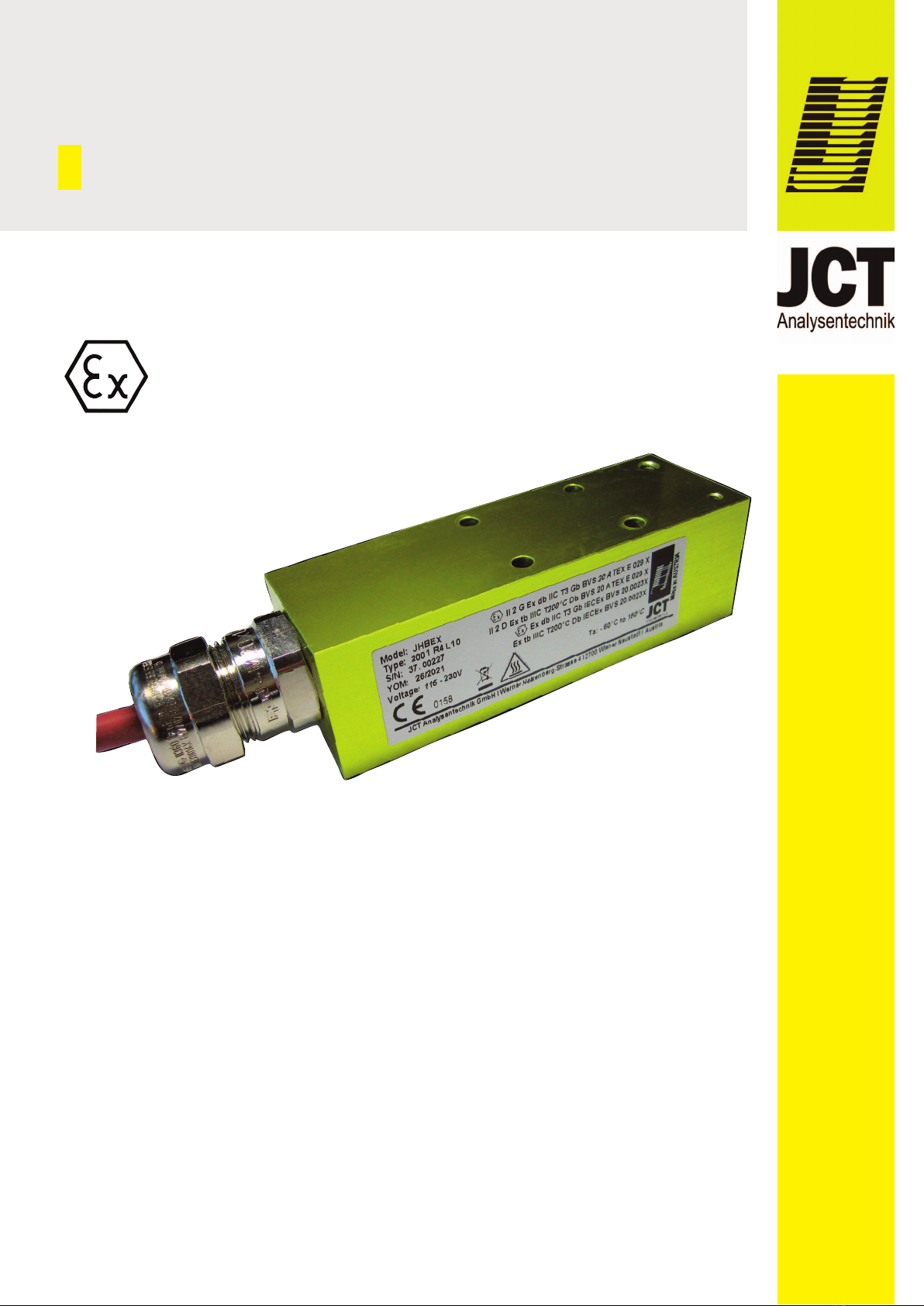
Product description1.4.
The heating block is used for heating in Ex zones.
The temperature is controlled by a maintenance-free,
selfregulating PTC heater element. An low temperature
sensor can be screwed on the outside for low tempe ra-
ture detection.For a correct and optimal selection, our
trained staff will be happy to assist you.
Intended use1.5.
The JHBEX is intended for heating in Ex areas of zone
1 and zone 2. A Heating of zone 0 is possible when the
JHBEX is mounted in zone 1. Please observe the infor-
mation in the technical specifications regarding power
supply and temperature limits.
This JHBEX may be operated in the hazardous areas
described on the type plate.
Correct storage1.6.
The JHBEX may be stored permanently under dry con-
ditiions between –20 °C and 60 °C.
Staff qualification1.7.
For the activities described in these operating instructi-
ons, a suitably qualified specialist is required. This
applies in particular for work in the fields
Product selection, configuration and modification•
Assembly, disassembly and storage of the device•
Installation•
Start up•
Maintenance and cleaning•
erfolgen. Eine Nichtbeachtung kann zu Sach- und/oder
Personenschäden führen.
Bei Nichtbeachtung der Sicherheitsvorrichtungen und
der in dieser Betriebsanleitung aufgeführten (Warn-)
Hinweise übernimmt JCT keine Haftung. Dies gilt sowohl
bei der Installation, beim Betrieb als auch bei Wartung.
Auch dann, wenn in dieser Bedienungs- und Wartungs-
anleitung nicht ausdrücklich darauf hingewiesen wird.
JCT haftet nicht für eigenmächtige Veränderungen am
Gerät sowie für unsachgemäße Bedienung oder Ver-
wendung. Wenn anzunehmen ist, dass ein gefahrloser
Betrieb nicht mehr möglich ist, muss dieses außer
Betrieb gesetzt und gegen unbeabsichtigten Betrieb
gesichert werden.Ein gefahrloser Betrieb ist nicht mehr
gegeben, wenn der JHBEX sichtbare Beschädigungen
aufweist
Wichtig:
Lesen Sie diese Betriebsanleitung vor Gebrauch sorg-
fältig durch und bewahren Sie sie zum Nachschlagen
auf.
Produktbeschreibung1.4.
Der JHBEX wurde für eine Beheizung in Ex-Zonen
entwickelt. Die Temperaturregelung erfolgt durch ein
wartungsfreies, selbstregelndes PTC-Heizelement.
Zur Untertemperaturerkennung kann außen ein Sensor
angeschraubt werden. Für eine korrekte und optimale
Auswahl steht Ihnen unser geschultes Personal gerne
zur Verfügung.
Bestimmungsgemäße Verwendung1.5.
Der JHBEX ist für die Beheizung von Ex-Bereichen der
Zone 1 und Zone 2 bestimmt. Eine Beheizung der Zone
0 ist möglich wenn der JHBEX in Zone 1 montiert wird.
Bitte beachten Sie die Angaben in den technischen
Spezifikationen hinsichtlich Stromversorgungs- und
Temperaturgrenzen.
Dieser JHBEX darf in den am Typenschild beschrieben
explosionsgefährdeten Bereichen betrieben werden.
Korrekte Lagerung1.6.
Der JHBEX kann dauerhaft unter trockenen Bedingun-
gen zwischen –20 °C und 60 °C gelagert werden.
Qualifikation des Personals1.7.
Für die in dieser Betriebsanleitung beschriebenen Tätig-
keiten ist eine entsprechend qualifizierte Fachkraft erfor-
derlich. Dies gilt vor allem für Arbeiten in den Bereichen
Produktauswahl, Projektierung und Modifikation•
Montage, Demontage und Lagerung des Geräts•
Installation•
Inbetriebnahme•
Wartung und Reinigung
•
Manual JHBEX

Professionals executing these tasks must have a level
of knowledge that includes relevant national standards
and regulations.
For operation in hazardous areas furhter knowledge is
required; a level of knowledge described in the follo-
wing standards is recommended:
IEC/EN 60079-0, IEC/EN 60079-14, IEC/EN 60079-
17, IEC/EN 60079-19
Description2.
Variants of JHBEX2.1.
BA_JHBEX_v1.21 ––––––––––––––– [ 5 / 15 ] –––––––––––––––––
Manual JHBEX
Fachkräfte, die diese Tätigkeiten ausführen, müssen einen
Kenntnisstand haben, der relevante nationale Normen und
Bestimmungen umfasst.
Für Tätigkeiten in explosionsgefährdeten Bereichen sind
weitere Kenntnisse erforderlich; empfohlen wird ein Ken-
nisstand der in folgenden Normen beschrieben ist:
IEC/EN 60079-0, IEC/EN 60079-14, IEC/EN 60079-17,
IEC/EN 60079-19
Beschreibung2.
Varianten des JHBEX2.1.
effects**...intended for mounting on pipelines and vessels where zone 0/zone 20 prevails.
einwirkend auf**…vorgesehen für die Montage auf Rohrleitungen und Behältern, in denen Zone 0/Zone 20 vorherrscht
JHBEX.
mounting
location /
Einbauort
effects** /
einwirkend
auf**
Temperature class /
Temperaturklasse
Ambient Temp. /
Umgebungstemp.
Marking of type of protection /
Kennzeichnung der Zündschutzart
3000 Zone 1 (21) Zone 0 (20) T2 / T 300 °C –60 °C...135 °C
II (1)2G Ex db [Ga] IIC T2 Gb BVS 20 ATEX E029 X
II (1)2D Ex tb [Da] IIIC T300 °C Db BVS 20 ATEX E029 X
Ex db [Ga] IIC T2 Gb IECEx BVS 20.0023X
Ex tb [Da] IIIC T300 °C Db IECEx BVS 20.0023X
2300 Zone 1 (21) Zone 0 (20) 230°C (T2)/ T230 °C
T2C (NEC) –60 °C...135°C
II (1)2G Ex db [Ga] IIC 230°C (T2) Gb BVS 20 ATEX E 029 X
II (1)2D Ex tb [Da] IIIC T230°C Db Gb BVS 20 ATEX E 029 X
Ex db [Ga] IIC 230°C (T2) Gb IECEx BVS 20.0023X
Ex tb [Da] IIIC T230°C Db IECEx BVS 20.0023X
2000 Zone 1 (21) Zone 0 (20) T3 / T 200 °C –60 °C...150 °C
II (1)2G Ex db [Ga] IIC T3 Gb BVS 20 ATEX E 029 X
II (1)2D Ex tb [Da] IIIC T200 °C Db BVS 20 ATEX E 029 X
Ex db [Ga] IIC T3 Gb IECEx BVS 20.0023X
Ex tb [Da] IIIC T200 °C Db IECEx BVS 20.0023X
1350 Zone 1 (21) Zone 0 (20) T4 / T 135 °C –60 °C...100°C
II (1)2G Ex db [Ga] IIC T4 Gb BVS 20 ATEX E 029 X
II (1)2D Ex tb [Da] IIIC T135 °C Db BVS 20 ATEX E 029X
Ex db [Ga] IIC T4 Gb IECEx BVS 20.0023X
Ex tb [Da] IIIC T135 °C Db IECEx BVS 20.0023X
2001 Zone 1 (21) Zone 1 (21) T3 / T 200 °C –60 °C...150 °C
II 2G Ex db IIC T3 Gb BVS 20 ATEX E 029 X
II 2D Ex tb IIIC T200 °C Db BVS 20 ATEX E 029 X
Ex db IIC T3 Gb IECEx BVS 20.0023X
Ex tb IIIC T200 °C Db IECEx BVS 20.0023X
1351 Zone 1 (21) Zone 1 (21) T4 / T 135 °C –60 °C...100 °C
II 2G Ex db IIC T4 Gb BVS 20 ATEX E 029 X
II 2D Ex tb IIIC T135°C Db BVS 20 ATEX E 029 X
Ex db IIC T4 Gb IECEx BVS 20.0023X
Ex tb IIIC T135 °C Db BVS 20.0023X
2302 Zone 2 (22) Zone 2 (22) 230°C (T2)/ T230 °C
T2C (NEC) –60 °C...135 °C
II 3G Ex dc IIC 230°C (T2) Gc BVS 20 ATEX E 034 X
II 3 D Ex tc IIIC T230°C Dc BVS 20 ATEX E 034 X
Ex dc IIC 230°C (T2) Gc IECEx BVS 20.0023X
Ex tc IIIC T230°C Dc IECEx BVS 20.0023X
2002 Zone 2 (22) Zone 2 (22) T3 / T 200 °C –60 °C...150 °C
II 3 G Ex dc IIC T3 Gc BVS 20 ATEX E 034 X
II 3 D Ex tc IIIC T200°C Dc BVS 20 ATEX E 034 X
Ex dc IIC T3 Gc IECEx BVS 20.0023X
Ex tc IIIC T200°C Dc IECEx BVS 20.0023X
1352 Zone 2 (22) Zone 2 (22) T4 / T 135 °C –60 °C...100 °C
III 3 G Ex dc IIC T4 Gc BVS 20 ATEX E 034 X
II 3 D Ex tc IIIC T135°C Dc BVS 20 ATEX E 034 X
Ex dc IIC T4 Gc IECEx BVS 20.0023X
Ex tc IIIC T135°C Dc IECEx BVS 20.0023X

BA_JHBEX_v1.21 ––––––––––––––– [ 6 / 15 ] –––––––––––––––––
Manual JHBEX
Ordercode2.2.Bestellcode2.2.
Verfügbare Varianten Available Features
Temperaturklassen Temperature class
T2 / T 300 °C 300 T2 / T 300 °C
T2C / T 230 °C 230 T2C / T 230 °C
T3 / T 200 °C 200 T3 / T 200 °C
T4 / 135 °C 135 T4 / 135 °C
einwirkend auf affect into
zone 0 (20) 0 zone 0 (20)
zone 1 (21) 1 zone 1 (21)
zone 2 (22) 2 zone 2 (22)
Montagefläche Mounting surface
gebogen R round
gerade F flat
Befestigung Mounting
ohne Montagelöcher 0 without mounting holes
2 Montagelöcher 2 2 mounting holes
4 Montagelöcher 4 4 mounting holes
ANSI/ISA-SP76 standard 6 ANSI/ISA-SP76 standard
Kabellänge Cable length
3 m L1 3 m
10 m L2 10 m
0,5 m L3 0,5 m
1 m L4 1 m
Kabelverschraubung Cable gland
nicht für Panzerrohr 0 not for conduit
für Panzerrohr (nur Adapter) 1 for conduit (only adapter)
Bestellcode / Order code JHBEX. L

Mounting surface2.3.
JHBEX with round contact surface2.3.1.
JHBEX with flat contact surface2.3.2.
Montagefläche2.3.
JHBEX mit gebogener Kontaktfläche2.3.1.
JHBEX mit flacher Kontaktfläche2.3.2.
BA_JHBEX_v1.21 ––––––––––––––– [ 7 / 15 ] –––––––––––––––––
Manual JHBEX
Anschluss für Erdung (M5 Gewinde)
Grounding position (M5 thread)
Anschluss für Untertemperaturkontakt (M3 Gewinde, max. 7 tief)
Mounting position for low temperature contact (M3 thread, max. 7 deep)
Wärmetransferfläche:
Muss vor Montage mit Wärmeleitpaste dünn bestrichen werden!
Heat transfer surface:
Must be coated thinly with heat-conductive paste before mounting!
Wärmeableitung über Kabelverschraubung verboten
Heat discipitation over cable clamp prohibited
Anschluss für Erdung (M5 Gewinde)
Grounding position (M5 thread)
Wärmetransferfläche:
Muss vor Montage mit Wärmeleitpaste dünn bestrichen werden!
Heat transfer surface:
Must be coated thinly with heat-conductive paste before mounting!
Anschluss für Untertemperaturkontakt (M3 Gewinde, max. 7 tief)
Mounting position for low temperature contact (M3 thread, max. 7 deep)
Wärmeableitung über Kabelverschraubung verboten
Heat discipitation over cable clamp prohibited
*laut Herstellervorgaben der Wärmeleitpaste
*according to the manufacturers specification of the heat-conductive paste
*laut Herstellervorgaben der Wärmeleitpaste
*according to the manufacturers specification of the heat-conductive paste

BA_JHBEX_v1.21 ––––––––––––––– [ 8 / 15 ] –––––––––––––––––
Manual JHBEX
Technical data3.
X-requirements / Specific comment for use4.
For all JHBEX:
The external groundingpoint must be connected to•
the local potential equalization.
Between 40°C und -60°C ambient temperature the•
heater must be permanently turned on!
Specific heat outputs are required for the different•
JHBEX types.
JHBEX.3000xxxxx
The heating block may only be operated screwed onto
a thermal load.
This must have a power output of at least 40 W.
Heat discipitation over cable gland prohibited.
JHBEX.2300xxxxx
This heating block may only be used in areas where the
heat output of the heating block is above Pmin.
Pmin [Watt] > = –0.25 * ambient temperature [°C] +101
This can be verified by calculation or measurement.
JCT-technicians can provide support if required.
Heat discipitation over cable gland prohibited.
Technische Daten3.
X-Anforderungen / Hinweise für den Einsatz4.
Für alle JHBEX gilt:
Der exterme Erdungspunkt muss mit dem lokalen•
Potentialausgleich verbunden sein.
Zwischen -40°C und -60°C Umgebungstemperatur•
muss der Heizer dauerhaft eingeschaltet sein!
Für die unterschiedlichen JHBEX Typen sind spe-•
zifische Wärmeabgaben erforderlich.
JHBEX.3000xxxxx
Der Heizblock darf nur auf eine thermische Last aufge-
schraubt betrieben werden!
Leistungsabgabe mindestens 40 W.
Wärmeableitung über Kabelverschraubung verboten.
JHBEX.2300xxxxx
Dieser Heizblock darf nur in Bereichen eingesetzt
werden, wo die Wärmeabgabe des Heizblocks über
Pmin liegt. Der Nachweis dazu kann rechnerisch oder
durch Messung erfolgen.
Bei Bedarf können JCT-Techniker unterstützen.
Pmin [Watt] >= –0,25 * Umgebungstemperatur [°C] +101
Construction
Mounting position coat the contact surface with heat-
transfer paste and apply it to the en-
tire surface
Weight 0,4 kg
Body material aluminium
Housing color yellow
Heating element PTC-heating element
Type of protection - flameproof enclosure - Gas
- protection with housing - Dust
Elektrik
Anschluss 115...230 V +/-10%, 50/60Hz
Leistungsaufnahme 30 W...200 W
Einschaltstrom < 2 A
Absicherung Bauseits, Auslösecharakteristik C;
230 VAC 6A; 115 VAC 10A
Mindestbiegeradius Kabel beweglich installiert: 55 mm
fest installiert: 29 mm
Kabeldurchmesser AD 7 mm; 3 x 1,0mm²
Electric
Connection 115...230 V +/-10 %, 50/60 Hz
Power consumption 30 W...200 W
Inrush current < 2 A
Fusing on site, fues characteristic C;
230 VAC 6A; 115 VAC 10A
Cable minimum
bend radius
moveable: 55 mm
fixed: 29 mm
Cable diameter OD 7 mm, 3 x 1,0 mm²
Operating data
Maximum temperature see 2.2 ordercode
permissible
ambient temperature
see 2.2 ordercode
Protection class IP66 & IP68
Approval / sign IECEx, ATEX, KCs, PESO, CE
Konstruktion
Einbau Kontaktflächen mit Wärmeleitpaste
bestreichen und vollflächig anliegend
montieren
Gewicht 0,4 kg
Gehäusematerial Aluminium
Gehäusefarbe Gelb
Heizelement PTC-Heizelement
Zündschutzart - druckfeste Kapselung - Gas
- Schutz durch Gehäuse - Staub
Betriebsdaten
Maximale Temperatur siehe 2.2 Bestellcode
zulässige
Umgebungstemperatur
siehe 2.2 Bestellcode
Schutzart IP66 & IP68
Zulassungen / Zeichen IECEx, ATEX, KCs, PESO, CE

BA_JHBEX_v1.21 ––––––––––––––– [ 9 / 15 ] –––––––––––––––––
Manual JHBEX
JHBEX.2000xxxxx
The heating block may only be operated screwed onto
a thermal load.
This must have a power output of at least 35 W.
Heat discipitation over cable gland prohibited.
JHBEX.1350xxxxx
The heating block may only be operated screwed onto
a thermal load.
This must have a power output of at least 35 W.
Heat discipitation over cable gland prohibited.
JHBEX.2001xxxxx
This heating block may only be used in areas where the
heat output of the heating block is above Pmin. The
proof of this can be provided by calculation or measure-
ment.
JCT-technicians can provide support if required.
Pmin [Watt] > = –0.25 * ambient temperature [°C] +71
Heat discipitation over cable gland prohibited.
JHBEX.1351xxxxx
The heating block may only be operated screwed onto
a thermal load!
This must have a power output of at least 35 W.
Heat discipitation over cable gland prohibited.
JHBEX.2302xxxxx
The heating block may only be operated screwed onto
a thermal load.
This must have a power output of at least 40 W.
Heat discipitation over cable gland prohibited.
JHBEX.2002xxxxx
There are no additional requirements for this heating
block.
JHBEX.1352xxxxx
There are no additional requirements for this heating
block.
Wärmeableitung über Kabelverschraubung verboten.
JHBEX.2000xxxxx
Der Heizblock darf nur auf eine thermische Last aufge-
schraubt betrieben werden!
Leistungsabgabe mindestens 35 W.
Wärmeableitung über Kabelverschraubung verboten.
JHBEX.1350xxxxx
Der Heizblock darf nur auf eine thermische Last aufge-
schraubt be trieben werden!
Leistungsabgabe mindestens 35 W.
Wärmeableitung über Kabelverschraubung verboten.
JHBEX.2001xxxxx
Dieser Heizblock darf nur in Bereichen eingesetzt wer-
den, wo die Wärmeabgabe des Heizblocks über Pmin
liegt. Der Nachweis dazu kann rechnerisch oder durch
Messung erfolgen.
Bei Bedarf können JCT-Techniker unterstützen.
Pmin [Watt] >= –0,25 * Umgebungstemperatur [°C] +71
Wärmeableitung über Kabelverschraubung verboten.
JHBEX.1351xxxxx
Der Heizblock darf nur auf eine thermische Last aufge-
schraubt be trieben werden!
Leistungsabgabe mindestens 35 W.
Wärmeableitung über Kabelverschraubung verboten.
JHBEX.2302xxxxx
Der Heizblock darf nur auf eine thermische Last aufge-
schraubt betrieben werden!
Leistungsabgabe mindestens 40 W.
Wärmeableitung über Kabelverschraubung verboten.
JHBEX.2002xxxxx
Es ist keine zusätzliche Anforderung für diesen Heiz-
block zu erfüllen.
JHBEX.1352xxxxx
Es ist keine zusätzliche Anforderung für diesen Heiz-
block zu erfüllen.

Assembly5.
Mechanical assembly5.1.
After unpacking inspect for transport damages•
Damaged parts must not be installed•
Check if JHBEX meets requirements of•
your Ex-zone
During installation zone release must be ensured•
JHBEX must be coated with heat-transfer paste on•
the contact surface. Application temperature of the
heat-transfer paste must fit to the temperature class
of the JHBEX typeplate.
Screw the JHBEX with full surface contact.•
Recommended tightening torque max. 2.4 Nm.
Electrical connection5.2.
Ensure zone clearance during assembly.•
Compare the local mains voltage, mains frequency•
and power consumption with the specifications on
the type plate.
Connect the JHBEX in accordance with the locally•
applicable regulations and additionally ground it via
the ground connection on the housing using a con-
ductor with a cross-section of at least 4 mm².
Correct connection is operator responsibility.•
Junction box with type of protection increased safety•
for the corresponding zone is recommended.
Strip the connection cable only up to a minimum of•
300 mm, measured from the cable gland.
(see figure on page 14).
Exposed strands may be shortened as required by
the customer.
Observe minimum bending radius of 29 mm for fixed•
mounted cable or 55 mm for moveable cable.
Do not damage the individual wires of the cable•
when stripping (notch).
Finishing the cable ends in accordance with the•
regulations and connect them in a suitable terminal
box.
Install strain relief for connection cable on the•
terminal box.
Tighten the union nut of the cable gland.•
Recommended tightening torque 20 Nm.
Montage5.
Mechanische Montage5.1.
Nach dem Auspacken auf Transportschäden•
untersuchen
Beschädigte Teile dürfen nicht verbaut werden•
Überprüfen, ob der JHBEX den Anforderungen•
Ihrer Zoneneinteilung entspricht
Während der Montage ist die Zonenfreigabe•
sicherzustellen
Der JHBEX ist an der Auflagefläche mit Wärmeleit-•
paste zu bestreichen. Temperaturbeständigkeit der
Wärmeleitpaste muss der Temperaturklasse am
Typenschlid des JHBEX entsprechen.
Den JHBEX vollflächig anliegend verschrauben.•
Empfohlenes Anzugsmoment max. 2,4 Nm.
Elektrischer Anschluss5.2.
Während der Montage Zonenfreigabe sicherstellen.•
Örtliche Netzspannung, Netzfrequenz und Leis-•
tungsaufnahme mit Angaben am Typenschild
vergleichen.
JHBEX entsprechend den örtlich geltenden•
Vorschriften anschliessen, sowie zusätzlich über
den Erdungsanschluss am Gehäuse, mit einem Lei-
ter von mindestens 4 mm² Querschnitts, erden.
Der Betreiber ist für den korrekten Anschluss•
verantwortlich.
Anschlussdose mit Zündschutzart erhöhte•
Sicherheit für die entsprechende Zone wird
empfohlen.
Das Anschlusskabel nur auf ein minimal 300 mm•
abisolieren (siehe Skizze auf Seite 14).
Freiliegende Litzen können nach Kundenwunsch
gekürzt werden.
Mindestbiegeradius von 29 mm für fix installiertes•
Kabel und 55 mm für bewegtes Kabel ist
einzuhalten.
Einzeladern des Kabels beim Abisolieren nicht•
beschädigen (einkerben).
Kabelenden vorschriftsgemäß endversogen und in•
einer geeigneten Klemmdose anschließen
Zugentlastung für Anschlusskabel an der Klemmen-•
dose installieren.
Überwurfmutter der Kabelverschraubung nachzie-•
hen. Empfohlenes Anzugsmoment 20 Nm.
BA_JHBEX_v1.21 ––––––––––––––– [ 10 / 15 ] –––––––––––––––––
Manual JHBEX

BA_JHBEX_v1.21 ––––––––––––––– [ 11 / 15 ] –––––––––––––––––
Manual JHBEX
WARNUNG
Bei arbeiten am Gerät spannungsfrei schalten.
Gegen Wiedereinschalten sichern.
Spannungsfreiheit feststellen.
Erden und Kurzschließen.
Benachbarte, unter Spannung stehende Teile
abdecken oder abschranken.
VORSICHT
Die Oberfläche des JHBEX kann sehr heiß sein.
Die Abkühlung ist abzuwarten und in jedem Fall
sind Schutzhandschuhe zu tragen!
VORSICHT
Die Kabelverschraubung im JHBEX darf nicht
gelöst werden!
VORSICHT
Der JHBEX kann an Netzspannung ange-
schlossen sein! Beim Betrieb des JHBEX
stehen bestimmte Teile im Inneren des JHBEX
unter gefährlicher Spannung!
Inbetriebnahme6.
Kontrolle der vorschriftsgemäßen Installation•
Überprüfung des JHBEX auf Beschädigung•
VORSICHT
Vor dem Einschalten ist sicherzustellen, dass
die am Typenschild angeführte Betriebsspan-
nung und die Netzspannung übereinstimmen!
HINWEIS
Die Farbe des JHBEX kann sich nach dem Auf-
heizen geringfügig verändern. Das hat
keinen Einfluss auf die Funktion.
WARNING
Disconnect the power supply when working on
the device.
Secure against being switched on again.
Check that no voltage is present.
Ground and short-circuit.
Cover or isolate adjacent live parts.
CAUTION
The device gets very hot during operation.
During any work on the JHBEX, it must be swit-
ched off! Wait for cool down and wear
protective gloves in any case!
CAUTION
The cable gland of the JHBEX must not be loo-
sened!
CAUTION
The JHBEX could be operated with mains vol-
tage! When operating the JHBEX, certain parts
inside the JHBEX are under dangerous voltage!
Start - up6.
Checking that installation is in accordance with•
regulations
Check JHBEX for damage•
CAUTION
Before power on, make sure that the operating
voltage indicated on the type plate and the
mains voltage match!
NOTICE
The colour of the JHBEX may change slightly
after heating up. This has no influence on
function.

BA_JHBEX_v1.21 ––––––––––––––– [ 12 / 15 ] –––––––––––––––––
Manual JHBEX
Maintenance7.
The JHBEX is basically maintenance-free.
Is is recommended to replace the JHBEX after 5 years
of operation in order to guarantee the function in the long
term.
The following must be checked as part of the regular
checks:
Visual check for damage to the cable gland and•
JHBEX or connection cable.
If damage is visible, the JHBEX must be replaced.
To do this, proceed as described under
disassembly.
Visual inspection for corrosion•
- slight discoloration from yellow into ochre is no
cause for concern.
- The JHBEX must be replaced if corrosion is visible
on the JHBEX
Visual inspection for dust deposits•
- during cleaning the zone release must be ensured.
- wait for the cool down of the surface of JHBEX.
- remove dust with a cloth moistened with tap water
Check tightening torque of cable gland.•
- while tightening the cable gland a zone release
must be ensured
- tighten the union nut of the cable gland. Recom-
mended tightening torque 20 Nm
Visual check of fixing screws if they have loosened:•
- during the retightening of the screws the zone
release must be ensured
- wait for cool down
- tighten the screws
Recommended tightening torque max. 2.4 Nm
Wartung7.
Der JHBEX ist grundsätzlich wartungsfrei.
Es wird empfohlen den JHBEX nach 5 Jahren Betriebs-
dauer zu tauschen, um dauerhaft die Funktion zu ge-
währleisten.
Im Rahmen der regelmäßigen Kontrollen ist folgendes
zu überprüfen:
Visuelle Kontrolle auf Beschädigungen von•
Kabelverschraubung, JHBEX und Anschlusskabel.
Sollten Beschädigungen sichtbar sein, ist der
JHBEX zu tauschen.
Dazu ist wie unter Demontage beschrieben
vorzugehen.
Visuelle Kontrolle auf Korrosion•
- Eine leichte Verfärbung von Gelb ins Ocker ist
kein Grund zur Besorgnis.
- Der JHBEX ist zu tauschen, wenn Korrosion am
JHBEX erkennbar ist.
Visuelle Kontrolle auf Staubablagerungen•
- während der Reinigung ist Zonenfreigabe sicher-
zustellen.
- Abkühlen der Oberfläche des JHBEX abwarten.
- Staub mit einem mit Wasser befeuchtetenTuch
entfernen.
Kontrolle Anzugsmoment Kabelverschraubung•
- während des Nachziehens des Kabelverschrau-
bers ist die Zonenfreigabe sicherzustellen
- Nachziehen der Überwurfmutter der Kabelver-
schraubung, empfohlenes Anziehmoment 20 Nm
Kontrolle der Fixierschrauben, falls locker:•
- während des Nachziehens der Schrauben ist die
Zonenfreigabe sicherzustellen
- Abkühlen abwarten
- Schrauben nachziehen
Empfohlenes Anzugsmoment max. 2,4 Nm

BA_JHBEX_v1.21 ––––––––––––––– [ 13 / 15 ] –––––––––––––––––
Manual JHBEX
Dismantling8.
During dismantling the zone release must be•
ensured
Disconnect mains of JHBEX from system side•
Wait for cool down•
Disconnect electrical connection•
Disconnect the ground connection from the housing•
Loosen the screws and remove the JHBEX•
Proper storage or disposal•
NOTICE
For repair purposes the applience must be sent
exclusively to JCT Analysentechnik GmbH. For
this purpose, the RMA-form on the website
must be filled out completely (www.jct.at/rma).
Otherwise, the appliance cannot be taken over
to protect the JCT employees.
Fault diagnostic9.
Recycling / Disposal10.
In accordance with Directive 2012/19/EU, these
devices must be disposed of correctly at the end
of their service life. The unit contains elements
which are suitable for recycling, and components
which need special disposal. You are therefore
requested to make sure that the unit will be recycled by
the end of its service life. Contact your local waste
disposal company or your local authority for more
information on this subject.
Demontage8.
Während der Demontage ist die Zonenfreigabe•
sicherzustellen
Den JHBEX anlagenseitig spannungsfrei machen•
Das Abkühlen abwarten•
Elektrischen Anschluss abklemmen•
Erdungsanschluss vom Gehäuse trennen•
Die Schrauben lösen und den JHBEX entfernen•
Fachgerechte Aufbewahrung bzw. Entsorgung•
HINWEIS
Zu Reparaturzwecken ist das Gerät ausschließ-
lich an JCT Analysentechnik GmbH zu schicken.
Dazu ist das RMA-Formular auf unserer Web-
site vollständig auszufüllen (www.jct.at/rma).
Andernfalls kann das Gerät zum Schutz der
JCT Mitarbeiter nicht übernommen werden.
Fehlerdiagnose9.
Recycling / Entsorgung10.
Entsprechend Richtlinie 2012/19/EU ist das
Gerät am Ende seiner Lebensdauer einer
geordnetenn Entsorgung zuzuführen. Das Gerät
enthält Bauteile, die wiederverwertet werden
müssen. Sorgen Sie deshalb dafür, dass das Gerät nach
der Verwendung der Wiederverwertung zugeführt wird.
Wenden Sie sich für nähere Auskünfte an Ihr örtliches
Entsorgungsunternehmen oder Ihre kommunale
Verwaltung.
Malfunction Cause / Remedy
Does not get warm
(does not heat)
– check power supply and fuses
– measure the electrical resistance of
the heating block.
If the resistance is more than 5000 Ω
the thermal fuse has tripped due to
overtemperature.
The heating block must be replaced!
Operating
temperature
not reached
– operating conditions are outside the
technical specifications:
check operating conditions
– check operation hours of heating
block
(natural aging recommended replace-
ment interval of 5 years)
Störung Ursache / Abhilfe
Wird nicht warm
(heizt nicht)
– Spannungsversorgung und
Sicherungen überprüfen
– Elektrischen Widerstand des
Heizblocks messen.
Sollte dieser mehr als 5000 Ω
betragen hat Temperatursicherung
wegen Übertemperatur ausgelöst.
Der Heizblock ist zu tauschen!
Betriebstemperatur
nicht errreicht
– Betriebsbedingungen sind außerhalb
der technischen Spezifikationen:
Betriebsbedingungen prüfen
– Kontrolle wie lange der Heizblock in
Betrieb war
(natürliche Alterung: empfohlenes
Austauschintervall von 5 Jahren)

Dimensions11.
JHBEX with round heat transfer surface11.1.
JHBEX with flat heat transfer surface11.2.
Abmessungen11.
JHBEX mit gebogener Wärmetransferfläche11.1.
JHBEX mit flacher Wärmetransferfläche11.2.
BA_JHBEX_v1.21 ––––––––––––––– [ 14 / 15 ] –––––––––––––––––
Manual JHBEX
JCT
108
L
min. 300
35
R40
66
6
6
3030
M3max.7mm
7
O
3G 1mm
²
Erdungsanschluss,
M5; max. 3,5Nm
33
~142
O
4,5
O
4,5
24SW
JCT
108
~142
29
50 min. 300
L
35
24
SW
Erdungsanschluss,
M5; max. 3,5Nm
24 24 6
6
6
O
4,5
M3max.7mm
7
O
3G 1mm²
O4,5

BA_JHBEX_v1.21 ––––––––––––––– [ 15 / 15 ] –––––––––––––––––
Zertifikate12.
ATEX Zertifikat12.1.
Über die nachstehenden QR-Codes gelangen Sie direkt
zum Download auf unserer Website.
IECEx Zertifikat12.2.
KCs Zertifikat12.3.
PESO Zertifikat12.4.
CE Erklärung12.5.
Certificates12.
ATEX certificate12.1.
The QR codes below will take you directly to the
download on our website.
IECEx certificate12.2.
KCs certificate12.3.
PESO certificate12.4.
CE declaration12.5.
Please refer to our website for more information about our products
Mehr Informationen zu unseren Produkten finden Sie auf unserer Website
JCT Analysentechnik GmbH Werner Heisenberg-Straße 4 2700 Wiener Neustadt Austria T+43 2622 87201 0 [email protected] www.jct.at
ERSTE BANK der österr. Sparkassen AG, BIC: GIBAATWWXXX, IBAN: AT25 2011 1829 4301 5600. UNICREDIT BANK AUSTRIA AG: BIC: BKAUATWW, IBAN: AT89 1100 0039 9372 2200
UID-Nr. / VAT-No: ATU20559900. Kreisgericht Wr. Neustadt: FN 119682 d, Geschäftsführer / CEO: Günter Zimmel
Manual JHBEX
https://jct.at/wp-content/uploads/2021/03/
JHBEX_Dekra_BVS-20-ATEX-E-029-
X_EU-Type-Examination-Certificate-1.pdf
Beheizung in ZONE 1 und/oder einwirkend auf ZONE 0
https://jct.at/wp-content/uploads/2021/03/
JHBEX_Dekra_BVS-20-ATEX-E-034-
X_EU-Type-Examination-Certificate-1.pdf
Beheizung in ZONE 2
https://jct.at/wp-content/uploads/2021/03/
JHBEX_IECEx_BVS_20.0023_000.pdf
https://jct.at/wp-content/uploads/2021/03/
JHBEX_Dekra_BVS-20-ATEX-E-029-
X_EU-Type-Examination-Certificate.pdf
heating in ZONE 1 and/or affecting in ZONE 0
https://jct.at/wp-content/uploads/2021/03/
JHBEX_Dekra_BVS-20-ATEX-E-034-
X_Type-Examination-Certificate.pdf
heating in ZONE 2
https://jct.at/wp-content/uploads/2021/03/
JHBEX_IECEx_BVS_20.0023_000.pdf
https://jct.at/wp-content/uploads/2021/03/
Ex-Certifica-Korea-Certi_JHBEX.pdf
https://jct.at/wp-content/uploads/2021/03/
Heater-Type-JHBEx-Aproved-CCOE-Certifi-
cate.pdf
https://jct.at/wp-content/uploads/2021/03/
CE_DE_JHBEX_v1.0.pdf
https://jct.at/wp-content/uploads/2021/03/
CE_DE_JHBEX_v1.0.pdf
https://jct.at/wp-content/uploads/2021/03/
Ex-Certifica-Korea-Certi_JHBEX.pdf
https://jct.at/wp-content/uploads/2021/03/
Heater-Type-JHBEx-Aproved-CCOE-Certifi-
cate.pdf
Table of contents
Other Jct Industrial Equipment manuals
Popular Industrial Equipment manuals by other brands

TSI Instruments
TSI Instruments CH-60 manual

Baumer
Baumer HOG 10 Mounting and operating instructions

Emerson
Emerson Fisher ENVIRO-SEAL instruction manual

Fröling
Fröling GAR 110 Installation and operating instructions

ABB
ABB HT563686 Operation manual

TE Connectivity
TE Connectivity AMP-O-LECTRIC G Customer's manual

Panasonic
Panasonic EXC14CG quick start guide

Balluff
Balluff BTL PF 400 C15A Series user guide

HANG
HANG 102-00 Operating instruction

ClockedIn
ClockedIn OnTIme Hardware installation guide

BWT
BWT Permaq Pro 2100 Series Installation and operating manual

InterTest
InterTest iShot Imaging MZ4 HD-UV GTIS Operation and service manual