Jet AFS-1000C Service manual

2
1.0 IMPORTANT SAFETY
INSTRUCTIONS
When using an electrical appliance, basic
precautions should always be followed, including
the following:
READ ALL INSTRUCTIONS BEFORE USING THIS
AIR FILTRATION UNIT.
To reduce the risk of fire,
electric shock, or injury:
1. Read and understand the entire owner's
manual before attempting assembly or
operation.
2. Read and understand the warnings posted
on the machine and in this manual. Failure
to comply with all of these warnings may
cause serious injury.
3. Replace the warning labels if they become
obscured or removed.
4. Do not use this air filtration system for other
than its intended use. If used for other
purposes, JET disclaims any real or implied
warranty and holds itself harmless from any
injury that may result from that use.
5. Never duct a machine directly into the air
filtration unit.
6. To avoid a potentially dangerous situation,
do not use this equipment to filter volatile
fumes or smoke.
7. Do not use this equipment to filter
flammable vapors. This air filtration unit is
designed and intended for the filtration of
air borne dust only. It is neither designed
nor intended for any other purpose
whatsoever.
8. Keep visitors a safe distance from the work
area. Keep children away.
9. Make your workshop child proof with
padlocks, master switches or by removing
starter keys.
10. DRUGS, ALCOHOL, MEDICATION. Do
not operate tool while under the influence
of drugs, alcohol or any medication.
11. Make certain the switch is in the OFF
position before connecting the machine to
the power supply.
12. Make certain the machine is properly
grounded.
13. Use recommended accessories; improper
accessories may be hazardous.
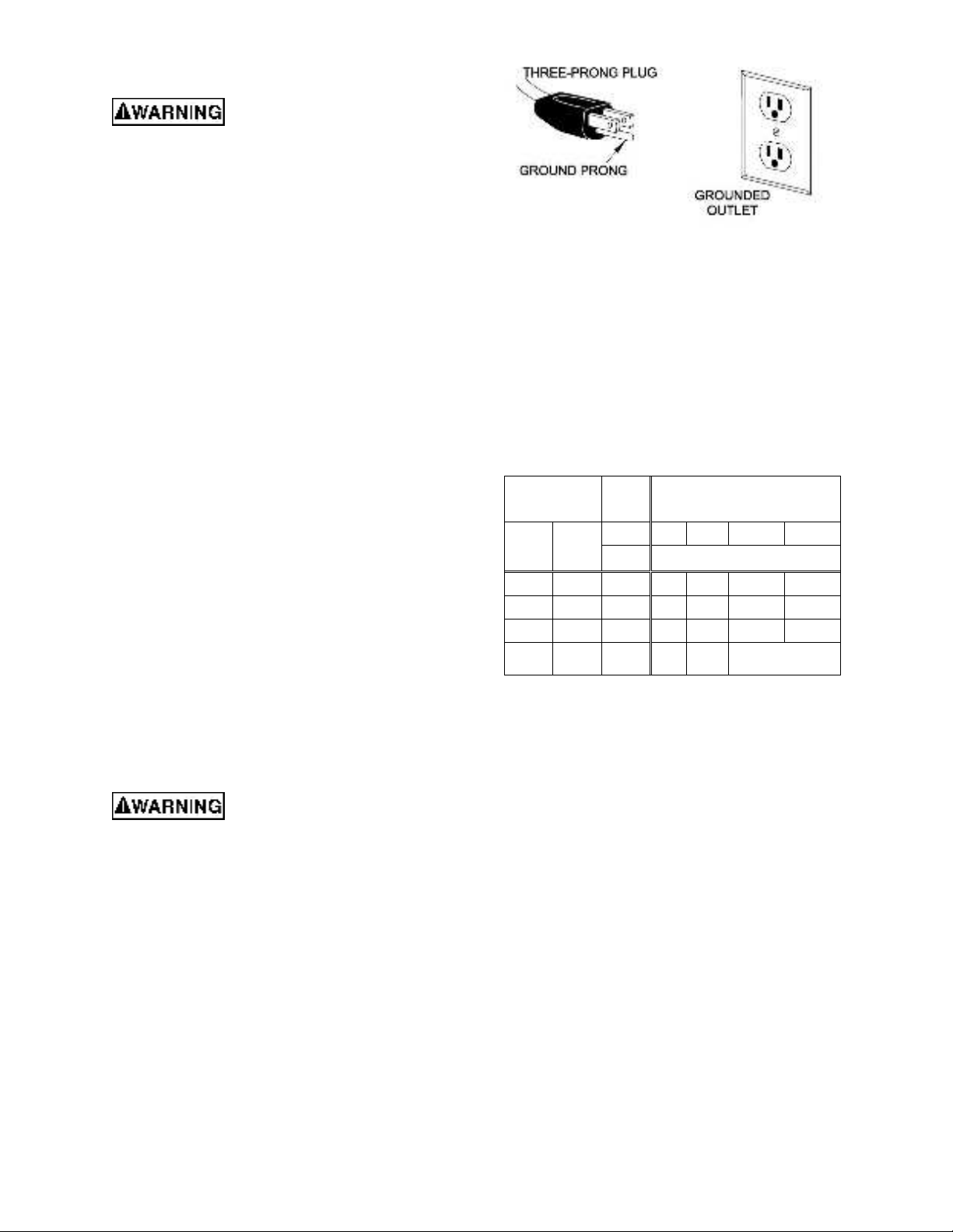
14. GROUND ALL TOOLS. If tool is equipped
with three prong plug, it should be plugged
into a three-hole electrical receptacle. If an
adapter is used to accommodate a two-
prong receptacle, the adapter lug must be
attached to a known ground. Never remove
the third prong.
15. WARNING: Drilling, sawing, sanding or
machining wood products generates wood
dust and other substances known to the
State of California to cause cancer. Avoid
inhaling dust generated from wood
products or use a dust mask or other
safeguards to avoid inhaling dust
generated from wood products. Wood
products emit chemicals known to the State
of California to cause birth defects or other
reproductive harm. (California Health and
Safety Code Section 25249.6)
16. Keep safety guards, panels, and doors in
place, secured, and always closed when
the machine is in use. If removed for
maintenance purposes, use extreme
caution and replace the guards, install the
panels and close the doors immediately
after completion of maintenance.
17. Maintain tools with care. Keep filters clean
for the best and safest performance.
18. Turn off the machine before cleaning. Use
a brush or compressed air to remove chips
or debris —do not use your hands.
19. Do not use this air filtration unit with a
damaged cord or plug. If the unit is not
working as it should, has been dropped,
damaged, left outdoors, or dropped into
water, return it to a service center.
20. When ceiling mounted, bottom of filtration
unit must be at least 7 feet from the floor.
The mounts must be anchored to building
structure which will support the weight of
the air filtration unit. Never mount to
surfaces such as dry wall or false ceiling
grids.
21. When bench top mounted, do not place this
unit on an unstable surface, or where there
is a risk of tipping over. Serious injury could
occur if the unit tips over.
22. To reduce risk of electric shock, do not
expose filtration unit to water or rain.
23. Do not use in high humidity environments.
Doing so may cause electric shock and/or
decreased performance of the unit.
24. WARNING: Not suitable for use with solid-
state speed controls.
25. Suitable for commercial or industrial use
only.

3
This device complies with Part 15 of the FCC Rules. Operation is subject to the following two conditions: (1) this
device may not cause harmful interference, and (2) this device must accept any interference received, including
interference that may cause undesired operation.
Caution: The user is cautioned that changes or modifications not expressly approved by the party responsible
for compliance could void the user's authority to operate the equipment.
Note: This equipment has been tested and found to comply with the limits for a Class B digital device, pursuant
to part 15 of the FCC Rules. These limits are designed to provide reasonable protection against harmful
interference in a residential installation. This equipment generates uses and can radiate radio frequency energy
and, if not installed and used in accordance with the instructions, may cause harmful interference to radio
communications. However, there is no guarantee that interference will not occur in a particular installation. If this
equipment does cause harmful interference to radio or television reception, which can be determined by turning
the equipment off and on, the user is encouraged to try to correct the interference by one or more of the following
measures:
—Reorient or relocate the receiving antenna.
—Increase the separation between the equipment and receiver.
—Connect the equipment into an outlet on a circuit different from that to which the receiver is connected.
—Consult the dealer or an experienced radio/TV technician for help.
This device contains licence-exempt transmitter(s)/receiver(s) that comply with Innovation, Science and
Economic Development Canada’s licence-exempt RSS(s). Operation is subject to the following two conditions:
1. This device may not cause interference.
2. This device must accept any interference, including interference that may
cause undesired operation of the device.
This equipment complies with IC RSS-102 radiation exposure limits set forth for an uncontrolled environment.
L’émetteur/récepteur exempt de licence contenu dans le présent appareil est conforme aux CNR d’Innovation,
Sciences et Développement économique Canada applicables aux appareils radio exempts de licence.
L’exploitation est autorisée aux deux conditions suivantes :
L’appareil ne doit pas produire de brouillage;
L’appareil doit accepter tout brouillage radioélectrique subi, même si le brouillage est susceptible d’en
compromettre le fonctionnement.
Cet équipement est conforme aux limites d’exposition aux radiations IC CNR-102 établies pour un environnement
non contrôlé.
Familiarize yourself with the following safety notices used in this manual:
This means that if precautions are not heeded, it may result in minor injury and/or
possible machine damage.
This means that if precautions are not heeded, it may result in serious, or possibly even
fatal, injury.
SAVE THESE INSTRUCTIONS
WARNING: Some dust, fumes and gases created by power sanding, sawing, grinding, drilling, welding and
other construction activities contain chemicals known to the State of California to cause cancer and birth defects
or other reproductive harm. Some examples of these chemicals are:
•lead from lead-based paint
•crystalline silica from bricks, cement and other masonry products
•arsenic and chromium from chemically treated lumber
Your risk of exposure varies, depending on how often you do this type of work. To reduce your exposure to
these chemicals, work in a well-ventilated area and work with approved safety equipment, such as dust masks
that are specifically designed to filter out microscopic particles. For more information go to
http://www.p65warnings.ca.gov/ and http://www. p65warnings.ca.gov/wood.

4
2.0 Table of contents
Section Page
1.0 IMPORTANT SAFETY INSTRUCTIONS ....................................................................................................... 2
2.0 Table of contents............................................................................................................................................ 4
3.0 About this manual .......................................................................................................................................... 5
4.0 Features .........................................................................................................................................................6
5.0 Specifications ................................................................................................................................................. 7
6.0 Setup..............................................................................................................................................................9
6.1 Unpacking and cleanup..............................................................................................................................9
6.2 Shipping contents.......................................................................................................................................9
6.3 Battery installation ...................................................................................................................................... 9
6.4 Installation ..................................................................................................................................................9
7.0 Electrical connections ..................................................................................................................................10
7.1 GROUNDING INSTRUCTIONS ...............................................................................................................10
7.2 Extension cords........................................................................................................................................ 10
8.0 Controls Functions ....................................................................................................................................... 11
8.1 Control Panel Buttons ..............................................................................................................................11
8.2 RF Remote Control ..................................................................................................................................11
9.0 Operation .....................................................................................................................................................12
10.0 User-maintenance......................................................................................................................................13
10.1 Changing the Filters ...............................................................................................................................13
10.2 Cleaning the Filters ................................................................................................................................13
10.2.1 Washable Filters..................................................................................................................................13
10.2.2 Dry Filters ............................................................................................................................................14
10.3 RF Remote Control Replacement .......................................................................................................... 14
10.4 Cleaning Sensors ................................................................................................................................... 14
10.5 Sensor Replacement.............................................................................................................................. 14
10.6 Control Board Replacement ...................................................................................................................14
11.0 Troubleshooting .........................................................................................................................................15
12.0 Replacement Parts.....................................................................................................................................16
12.1.1 AFS Unit –Exploded View ..................................................................................................................16
12.1.2 AFS Unit –Parts List ........................................................................................................................... 17
12.2.1 Display Module Assembly –Exploded View .......................................................................................18
12.2.2 Display Module Assembly –Parts List ................................................................................................18
12.3.1 Remote Control Assembly –Exploded View.......................................................................................19
12.3.2 Remote Control Assembly –Parts List................................................................................................ 19
13.0 Electrical Connections 115V ...................................................................................................................... 20
14.0 Warranty and service .................................................................................................................................21

5
3.0 About this manual
This manual is provided by JET, covering the safe operation and maintenance procedures for a JET Model AFS-
1000C Air Filtration System. This manual contains instructions on installation, safety precautions, general
operating procedures, maintenance instructions and parts breakdown. Your machine has been designed and
constructed to provide consistent, long-term operation if used in accordance with the instructions as set forth in
this document.
This manual is not intended to be an exhaustive guide to air filtration systems. Additional knowledge can be
obtained from experienced users or trade articles. Whatever accepted methods are used, always make personal
safety a priority.
If there are questions or comments, please contact your local supplier or JET. JET can also be reached at our
web site: www.jettools.com.
Retain this manual for future reference. If the machine transfers ownership, the manual should accompany it.
Read and understand the entire contents of this manual before attempting assembly or
operation! Failure to comply may cause serious injury!
Register your product online -
http://www.jettools.com/us/en/service-and-support/warranty/registration/

6
4.0 Features
•Two-filter system with air diffuser disperses outgoing air into a broader pattern
•Disposable electrostatic outer filter attracts more dust particles than standard filters
•Inner pocket filter is removable for easy cleaning
•Can be either bench-top or ceiling mounted
oFour eye bolts provided for ceiling mount
•Large easy to read display panel clearly shows:
oFilter Status
▪Patent Pending system monitors the condition of the filters
▪Bright LED indicators notify the user of the filter status
•GOOD
•REPLACE SOON
•REPLACE
oFan Speed – 6 levels
oTimer setting
▪1 to 16 hours in 1-hour increments
▪automatically shuts off when timer runs out
•High-efficiency Brushless DC motor
oImproved durability
oQuieter operation
oMore energy efficient
•Auto Mode:
oIn Auto Mode the unit monitors ambient air quality using an integrated PM2.5
sensor and adjusts fan speed to compensate
oMore air flow when it’s needed to quickly improve air quality
oSave energy and filter life when dust levels are low
•Patent Pending air flow design not only increases air volume but also decreases noise.
•High strength plastic construction:
oReduced weight for ease of installation compared to sheet metal construction
oAbsorbs vibration for quieter operation
oImpact resistant

7
5.0 Specifications
Table 1
Model No.
AFS-1000C
Stock No.
713000
SPECIFICATION
Motor:
Motor type
BLDC (Brushless Direct Current Motor)
Horsepower
1/3HP
Phase
3PH
Electrical:
Voltage
120V input, single phase only
Frequency
60Hz
Listed FLA (full load amps)
3.8 A
Motor speed range
600~1,100 RPM
Power cord
SJT 18 AWG x 3C, 6 ft,
Power plug
American Type NEMA (10A/125V)
Overload protector
5A
Performance:
Fan Speed
Air flow without filter
(CFM) 1
Sound rating @ 1m 1
1
450 ±10%
51dB
2
560 ±10%
56dB
3
670 ±10%
60dB
4
780 ±10%
63dB
5
890 ±10%
66dB
6
1000 ±10%
67dB
Control Panel:
On/off switch
Rocker switch
Speed control
Six selectable speeds
Timer Setting (Hour)
1 ~ 16 (LED display)
Display
LED module
Digital Remote Control:
Transmitter
Radio Frequency
Battery
CR2032.3 Volt Button Cell
Filters:
Outer Filter (stock # 708731)
5 Micron Replacement Electrostatic Out Filter (carton frame)
Inner Filter (stock # 708733)
1 Micron Replacement Inner Filter

8
Table 1 (cont.)
Dimensions and Weight:
Overall Dimension (L x W x H / in)
30 x 24 x 15 / in
Packing Dimension (L x W x H / in)
33 x 27 x 19 / in
Packing Material
Corrugated Box and Styrofoam
Net Weight (lbs.)
33Ibs (15 kg)
Gross Weight (lbs.)
41.8lbs (19 kg)
1Variable of ±10%, for general information only, not to be viewed as fixed parameters for inspection purposes.
L = length, W = width, H = height
n/a = not applicable
The specifications in this manual were current at time of publication, but because of our policy of continuous
improvement, JET reserves the right to change specifications at any time and without prior notice, without
incurring obligations.

9
Read and understand the
entire contents of this manual before attempting
assembly or operation. Failure to comply may
cause serious injury.
6.0 Setup
6.1 Unpacking and cleanup
Inspect the Air Filtration Unit and check for shipping
damage. Report any damage immediately to your
distributor and shipping agent. Do not discard any
shipping material until the Air Filtration Unit is
installed and running properly.
Compare the contents of your container with the
following parts list to make sure all parts are intact.
Missing parts, if any, should be reported to your
distributor.
6.2 Shipping contents
Carton contents
1 Air Filtration Unit
1 Remote Control
1 CR2032 Battery
1 Manual and Warranty Card
4 Eye Bolts
6.3 Battery installation
1. Remove the battery cover on the rear of the
remote control as shown in Fig. 6-1.
2. Install the supplied battery (CR2032) with the “+”
side facing upward (Fig. 6-1).
3. Replace the battery cover.
Figure 6-1
6.4 Installation
6.4.1 Overhead (ceiling)
Overhead structure (often
ceilings) must be capable of supporting the
weight of the air filtration unit and absorbing any
vibrations arising from the unit. Appropriate
fasteners must be used to secure to the ceiling.
Failure to comply may cause serious injury.
Never mount to surfaces such as dry wall, false
ceiling grids, etc.
When overhead mounting such as a ceiling, make
sure chain and ceiling hooks are properly rated for
hanging this unit.
Refer to figure 6-2. After noting the direction of air
flow, use the hole location dimension to place the
anchors in the ceiling so that the chains hang as
straight as possible.
Clearance should be at least 7 feet from bottom of
unit to the floor.
Figure 6-2
This unit will work best if located away from corners
and heating/cooling vents.
6.4.2 Benchtop
When bench top mounting is used, make sure that
the surface is flat and level and does not allow the
AFS to move over the surface which could allow it
to fall.
Verify that the bench is stable and secure and will
not tip causing the AFS to fall.
In either installation:
•Route the power cord so that it will NOT
become entangled in the machine in any
way.
•Route the cord to the power supply in a way
that does NOT create a trip hazard.
Air Flow
20-1/16”
13”
22-3/8”

10
7.0 Electrical connections
Electrical connections should
be made by a qualified electrician in compliance
with all relevant codes. Failure to comply may
cause serious injury.
The AFS-1000C Air Filtration System is prewired for
single phase, 120V power. It is provided with a plug
designed for use on a circuit with a grounded outlet
that looks like the one pictured in Figure 7-1.
It is recommended that the AFS-1000C be
connected to a 15 amp circuit with a circuit breaker
or fuse. If fuses are used, they should be time-delay
fuse marked “D”. Local codes take precedence
over recommendations.
7.1 GROUNDING INSTRUCTIONS
1. All Grounded, Cord-connected Tools:
This machine must be grounded. In the event of a
malfunction or breakdown, grounding provides a
path of least resistance for electric current to reduce
the risk of electric shock. This tool is equipped with
an electric cord having an equipment-grounding
conductor and a grounding plug. The plug must be
plugged into a matching outlet that is properly
installed and grounded in accordance with all local
codes and ordinances.
Do not modify the plug provided - if it will not fit the
outlet, have the proper outlet installed by a qualified
electrician.
Improper connection of the equipment-grounding
conductor can result in a risk of electric shock. The
conductor with insulation having an outer surface
that is green with or without yellow stripes is the
equipment-grounding conductor. If repair or
replacement of the electric cord or plug is necessary,
do not connect the equipment-grounding conductor
to a live terminal.
Check with a qualified
electrician or service personnel if the grounding
instructions are not completely understood, or if
in doubt as to whether the tool is properly
grounded. Failure to comply may cause serious
or fatal injury.
Use only 3-wire extension cords that have 3-prong
grounding plugs and 3-pole receptacles that accept
the tool's plug.
Repair or replace damaged or worn cord
immediately.
2. Grounded, cord-connected tools intended for use
on a supply circuit having a nominal rating less than
150 volts:
This tool is intended for use on a circuit that has an
outlet that looks like the one illustrated in Figure 7-
1.
Figure 7-1
7.2 Extension cords
The use of extension cords is discouraged. Try to
position machines within reach of the power source.
If an extension cord must be used, make sure it is
heavy enough to carry the current your product will
draw. An undersized cord will cause a drop in line
voltage resulting in loss of power and overheating.
Table 2 shows correct size to use depending on
cord length and nameplate ampere rating. If in doubt,
use the next heavier gauge. The smaller the gauge
number, the heavier the cord.
Ampere
Rating
Volts
Total length of cord in feet
More
Than
Not
More
Than
120
25
50
100
150
AWG
00
06
18
16
16
14
06
10
18
16
14
12
10
12
16
16
14
12
12
16
14
12
Not
Recommended
Extension Cord Recommendations
Table 2

11
8.0 Controls Functions
8.1Control Panel Buttons
Figure 8-1
8.2RF Remote Control
Figure 8-2
POWER ON/OFF SWITCH –A
The Power ON/OFF switch (Fig. 8-1, A) is a rocker
switch on the control panel used to supply power to
the AFS electronic controls and thus the full AFS.
In the OFF position, AC power is disconnected from
the electronics. The AFS unit will Not turn On.
In the ON position, AC power is connected to the
electronics. The electronics are powered On in a
STANDBY state awaiting user input via the ON/OFF
button on either the control panel or the remote.
ON/OFF BUTTON (control panel or
remote) –B
The On/Off Button (Fig. 8-1 and 8-2, B) on the
controls and the remote perform the exact same
function under the exact same conditions.
When the Power switch (Fig. 8-1, A) is first turned
ON, power is supplied to the electronics and the
AFS unit is in the STANDBY state. All DISPLAYs
are off.
Each press of the ON/OFF button (Fig. 8-1 and 8-2,
B) cycles the AFS unit between STANDBY and ON.
Pressing the ON/OFF button once:
•AFS Unit goes to ON state.
•The TIMER DISPLAY is blank.
•The fan starts to run at speed 1.
•The SPEED DISPLAY shows 1 bar for speed 1.
•The FILTER DISPLAY will illuminate the filter
status.
Pressing the ON/OFF button again does the
following:
•AFS unit goes to STANDBY state.
•All DISPLAYS are off, and the fan stops.
TIMER (control panel or remote)
The TIMER buttons (Fig. 8-1 and 8-2) on the
controls and the remote perform the exact same
function under the exact same conditions.
The TIMER may be set in 1-hour increments from 1
to 16 hours. When the timer expires, the fan will stop
and the AFS will enter STANDBY state.
When the timer is not being used, the TIMER display
will be blank and the AFS will run continuously until
the user changes the settings or stops the AFS.
To activate the TIMER, pressing the TIMER + button.
•The TIMER DISPLAY changes from blank to
display flashing “1”. This is 1 hour.
•Pressing the TIMER + button again will increase
the number by 1 each time the TIMER + button
is pressed. Up to a maximum of 16 hours.
•Pressing the TIMER –button will decrease the
number by 1 each time the TIMER - button is
pressed. Down to a blank display turning the
TIMER Off and running the AFS continuously.
•If the display is already set and showing an hour
time value, then pressing the TIMER + or –
button will add or subtract time from the already
set value.
•When the TIMER + or –button have been
pressed, the number on the TIMER display will
flash for 1 second and then show steady ON.
Steady ON indicates the TIMER is set and the
countdown has begun.
•Pressing and holding either the TIMER + or –
button (2 seconds) will advance the count
quickly (changing every 0.2 seconds) until the
button is released.
A
B
B

12
FAN SPEED ADJUSTMENT (control
panel or remote)
The SPEED Buttons (Fig. 8-1 and 8-2) on the
controls and the remote perform the exact same
function under the exact same conditions.
The SPEED display uses illuminated bars to
indicate which speed level is active. The upper most
illuminated bar is the current speed setting. The bars
not lit are still available to increase fan speed if
desired.
Air flow at each fan SPEED setting is as follows:
Fan Speed Setting
CFM
1
450 ±10%
2
560 ±10%
3
670 ±10%
4
780 ±10%
5
890 ±10%
6
1000 ±10%
Table 3
When the AFS is turned ON, the fan will start and
run at SPEED 1 until changed by the user. The
SPEED display will show 1 bar.
•Pressing the SPEED + button will increase the
fan speed.
•Pressing the SPEED –button will decrease the
fan speed.
AUTOMATIC MODE
NOTE: For best performance in AUTO mode, allow
adequate air flow to the sensor on the bottom of the
unit (see Fig. 8-3).
Figure 8-3
The AUTO buttons (Fig. 8-1 and 8-2) on the controls
and the remote perform the exact same function
under the exact same conditions.
When the AUTO button is pressed, the AUTO button
is illuminated, and the AFS is operating in AUTO
mode.
In AUTO mode, the integrated sensor detects the air
quality and adjusts the fan speed accordingly.
Thereby reducing energy consumption when air
quality is good and increasing the fan speed when
dust is present.
•Pressing either the SPEED + or –button will
deactivate AUTO mode and return to manual
mode.
NOTE: In AUTO mode the unit may require
several minutes to return to fan speed 1 once
dust is detected. The unit intentionally ramps
down slowly to ensure good shop air quality.
FILTER STATUS INDICATOR (control
panel)
The FILTER status indicators are located on the
control panel and are there to indicate the condition
of the filters.
"GOOD" indicates that the filters are clean enough
to provide effective filtration.
"REPLACE SOON" indicates that the filters are
becoming clogged, reducing the units ability to
effectively filter the shop air, and therefore will need
to be cleaned/replaced soon.
REPLACE" indicates that the filter is clogged to the
point that it needs to be cleaned or replaced.
9.0 Operation
NOTE: The Air Filtration Unit is designed to remove
airborne non-metallic dust particles; it is not
designed to take the place of a dust collection
system.
Larger particles are trapped by the outer filter.
Smaller particles are stopped by the fine mesh
pockets of the inner filter. The air is then exhausted
through the diffusion filter, which has a fibrous
composition to help diffuse the air.
Normal operation:
•At the Control panel, place Power On/Off switch
to ON.
•From either the Control panel or Remote, press
the On/Off button.
•Set the SPEED as desired or select AUTO.
•If desired, set the TIMER to automatically turn
off at a later time.
•At the end of the day/shift/leaving for an
extended period of time, press the On/Off
button to stop the fan.
•If leaving for a longer period of time such as
weekend or vacation, turn the Power switch to
Off as well.
Sensor

13
10.0 User-maintenance
Always disconnect power to
the machine before performing maintenance.
Failure to do this may result in serious personal
injury.
10.1 Changing the Filters
To reduce the risk of injury,
disconnect the air filtration system from the
power source (unplug) before servicing or
changing filters. Failure to comply may cause
serious injury!
There are two filters that need to be changed.
Filter life will vary depending on the amount of usage
and the environment of your shop. Clogged filters
will reduce the amount of air circulation.
1. Lift the filter up and pull outward on the bottom
edge to remove the filter.
Figure 10-1
2. Remove the inner filter by pulling straight out of
the cabinet.
3. Remove any protective wrapping from the new
filters.
4. Install the filters in reverse of the removal. The
outer filter has directional air flow arrows printed
on the frame which depicts the direction of air
flow. Make sure it is facing the proper direction
when installed. If no directional arrows are
present, the inboard side of the filter will
typically have metal support not used on the
outboard side.
Replacement Filters:
NOTE: JET brand filters are recommended for best
performance.
708731 ......Electrostatic Outer Filter
708732 ......Washable Electrostatic Outer Filter
708733 ......Inner Three-Pocket Filter
708734 ......Charcoal Filter
10.2 Cleaning the Filters
To reduce the risk of injury,
disconnect the air filtration system from the
power source (unplug) before servicing or
changing filters. Failure to comply may cause
serious injury!
This AFS is designed to remove airborne non-
metallic dust particles from the air. Cleaning is about
removing those particles from the filter in the
opposite direction from which it came.
It is recommended to clean both filters at the same
time. Whether using the Filter Status Indicator or a
visual inspection, both filters should be cleaned to
restore as much filtration ability as possible.
Remove the filters from the AFS unit as described
in 10.1 Changing the Filters.
10.2.1Washable Filters
Washable filters are those filters which may get wet
and allowed to dry before returning to service. The
replacement Washable Electrostatic Outer Filter
(P/N 708732) is a washable filter.
Figure 10-2 Inside of filter shown.
•Using a hose and spray nozzle with normal tap
water pressure, spray the filter from the inside
out. Opposite the operating air flow. This will
rinse the larger loose particles out of the filter.
•Mix a mild detergent and water mixture (soap)
such as dish soap. Mix a drop or two of dish
soap and water into a spray bottle. If using a
commercial electrostatic detergent, follow the
label instructions.
•Spray the soap onto the entire filter until fully
covered.
•Allow the soap to soak 1 to 2 minutes on the
filter but do not allow the soap to dry. This will
create a sticky film that is difficult to remove.
•Thoroughly rinse the soap out of the filter and
the filter frame.

14
•Allow all excess water to drain off the filter.
While the filter does not need to be absolutely
dry, do not return to service if water is dripping
or droplets are still visible.
•Low pressure compressed air may be used to
remove any remaining water from the filter.
•Install the filters in reverse of the removal. The
outer filter has directional air flow arrows printed
on the frame which depicts the direction of air
flow. Make sure it is facing the proper direction
when installed. If no directional arrows are
present, the inboard side of the filter will
typically have metal support not used on the
outboard side.
10.2.2 Dry Filters
Dry filters are those filters which should not get wet.
The standard Electrostatic Outer Filter (P/N 708731)
is a dry filter.
Cleaning may be completed by vacuuming using a
brush attachment on the vacuum hose.
•Lightly brush the vacuum brush nozzle over the
input side of the filter. The brush will help
dislodge the particles which will then be
removed by the vacuum.
•Make several passes moving inline with the
pleats of the filter.
•Visually inspect the filter while cleaning. If the
filter material is worn, torn, or coming apart from
the frame, it must be replaced.
10.3 RF Remote Control Replacement
Figure 10-3
The remote control provided with the AFS unit is
programmed and ready to operate once the unit is
installed. Verify that the batteries are installed in the
remote.
Follow these instructions if the remote is being
replaced.
1. Place the Power switch in the ON position.
2. DO NOT press the ON/OFF button.
3. Press and hold the SPEED –(minus) and
SPEED + (plus) buttons on the control panel at
the same time and hold for two seconds. The
screen flashes (0.5 seconds) and displays "---"
to enter the programming mode.
4. Press and hold the ON/OFF button of the
REMOTE control until the panel is turned ON
("ON" is displayed), and the programming is
complete.
5. In the programming mode, press any other
button on the control panel to exit the
programming mode.
6. In the programming mode, if the programming
is not completed within seven seconds, you will
leave the programming mode.
10.4 Cleaning Sensors
Dust may accumulate on the sensor (see Fig. 8-3)
and affect the performance in AUTO mode. Sensor
may be cleaned with a dry cloth or compressed air.
10.5 Sensor Replacement
The AFS unit ships from the factory with the sensor
and control board calibrated and ready to use. In
the event the sensor should need replacing, follow
these instructions to calibrate the new sensor:
1. With the Power ON/OFF switch (Fig. 10-4, A) in
the OFF position, press and hold the Timer-
DN(-) and Timer-UP(+) buttons simultaneously,
then switch the Power ON/OFF switch to the
ON position to enter the environment value
setting mode.
2. The screen flashes and displays “- -", the
calibration is completed when the detected
value is stable (- - disappears), and then returns
to the standby state.
Figure 10-4
10.6 Control Board Replacement
In the event the control board needs replacing,
follow the steps in Section 10.5 to calibrate the
sensor with the new control board. Then follow
these instructions to program the remote to operate
with the new control board:
1. Recalibrate the sensor to the new control board.
2. Pair the new control board with the remote
control, reference Section 10.3.
A
B

15
11.0 Troubleshooting
Table 4
Symptom
Probable Cause
Remedy
AFS will not start
Power ON/OFF switch in the OFF
position
Move Power ON/OFF switch to the ON
position.
No incoming power
Check plug connection
Verify there is power at the outlet, check
breaker or fuse panel.
Low voltage
Request voltage check form power
company and correct low voltage
condition.
Power cord damaged
Replace power cord.
Control button or PCBA malfunction
Contact JET customer service.
Excessive vibration
Loose frame, parts, or fasteners
Inspect and tighten as needed.
Impeller imbalance
Clean impeller (do not use solvents).
If imbalance still occurs, replace impeller.
Motor imbalance
Have motor tested by qualified personnel;
replace if needed.
Unit not responding to
remote control
Weak batteries in remote
Replace batteries.
Radio frequency interference
Identify sources of interference and
eliminate them or relocate unit.
Remote control or machine control panel
malfunction
Contact JET customer service.
Unit not working
efficiently; not cleaning
air.
Filter not installed properly
Reinstall filter.
Blocked air flow
Inspect filter; replace if clogged
remove blockage.
Controls on unit not
working
Control button or PCBA malfunction
Contact JET customer service.
Timer screen displays
numbers / letters other
than a countdown timer
If screen displays A8 filter is not installed
Install filter.
Control may be in factory set-up mode
Move power ON/OFF switch to the OFF
position. Wait 30 seconds, then switch
back to ON. Then press the On/Off
button.
Loose connection on the control board
Move power ON/OFF switch to the OFF
position and unplug the unit. Check the
electrical connections to the control
board to ensure they are all seated
properly.
Control button or PCBA malfunction
Replace control board.
Contact JET customer service.
*Warning: Some corrections may require a qualified electrician.

16
12.0 Replacement Parts
Replacement parts are listed on the following pages. To order parts or reach our service department, call 1-800-
274-6848 Monday through Friday, 8:00 a.m. to 5:00 p.m. CST. Having the Model Number and Serial Number of
your machine available when you call will allow us to serve you quickly and accurately.
12.1.1 AFS Unit –Exploded View

17
12.1.2 AFS Unit –Parts List
Index No Part No Description Size Qty
1 ................AFS1000C-001 ......... Motor........................................................................ ..................................... 1
2 ................AFS1000C-002 ......... Fan blade (Right) ..................................................... ..................................... 1
3 ................AFS1000C-003 ......... Fan blade (Left) ....................................................... ..................................... 1
4 ................AFS1000C-004 ......... Deflector .................................................................. ..................................... 2
5 ................AFS1000C-005 ......... Air filter lower case .................................................. ..................................... 1
6 ................AFS1000C-006 ......... Air filter upper case.................................................. ..................................... 1
7 ................AFS1000C-007 ......... Air filter bezel........................................................... ..................................... 1
8 ................ .................................. Display Module Assembly (SEE 12.2.1 for detail) ... ..................................... 1
9 ................AFS1000C-009 ......... Nets ......................................................................... ..................................... 1
10 ..............708733 ...................... Inner three-pocket filter............................................ ..................................... 1
11 ..............708731 ...................... Electrostatic outer filter ............................................ ..................................... 1
12 ..............AFS1000C-012 ......... Dust sensor cover.................................................... ..................................... 1
13 ..............AFS1000C-013 ......... Bottom cover............................................................ ..................................... 1
14 ..............AFS1000C-014 ......... Dust sensor.............................................................. ..................................... 1
15 ..............AFS1000C-015 ......... Power cord............................................................... ..................................... 1
16 ..............JET-79B .................... JET Stripe (7.67"X9.05").......................................... ..................................... 1
17 ..............AFS1000C-MD.......... Model Decal 1000C ................................................. ..................................... 1
18 ..............AFS1000C-018 ......... Warning label........................................................... ..................................... 1
19 ..............AFS1000C-019 ......... Cable glands............................................................ ..................................... 1
20 .............. .................................. Remote Control Assembly (SEE 12.3.1 for detail) .. ..................................... 1
21 ..............AFS1000C-021 ......... Eye bolt.................................................................... M6X20 .......................... 4
22 ..............AFS1000C-022 ......... Standoff ................................................................... M6X25 .......................... 4
23 ..............TS-1550041 .............. Flat washer .............................................................. M6 ............................... 13
24 ..............TS-1534032 .............. Screw, Pan Head, Phillips ....................................... M6X10 .......................... 5
25 ..............TS-2286202 .............. Screw, Pan Head, Phillips ....................................... M6X20 .......................... 2
26 ..............AFS1000C-023 ......... Hex head bolt .......................................................... M6X300 ........................ 6
27 ..............TS-1551041 .............. Spring washer.......................................................... M6 ................................. 7
28 ..............AFS1000C-024 ......... Screw, Pan Head, Phillips (Tapping screw) ............ M5X12 .......................... 8
29 ..............AFS1000C-025 ......... Flat head screw (Tapping screw) ............................ M4X10 .......................... 8
30 ..............AFS1000C-026 ......... Flat head screw (Tapping screw) ............................ M3X10 .......................... 1
31 ..............AFS1000C-027 ......... Motor Label (not shown).......................................... ..................................... 1
32 ..............AFS1000C-028 ......... ID Label (not shown) ............................................... ..................................... 1
33 ..............AFS1000C-029 ......... Energy star Label (not shown)................................. ..................................... 1
34 ..............AFS1000C-030 ......... Display cable (not shown) ....................................... ..................................... 1
35 ..............AFS1000C-031 ......... Dust sensor cable (not shown) ................................ ..................................... 1
36 ..............AFS1000C-HK .......... Hardware kit includes 4x item 21 (eye bolts) and item 20 (remote control assembly)... 1
Replacement Filters:
..................708731 ...................... Electrostatic Outer Filter
..................708732 ...................... Washable Electrostatic Outer Filter
..................708733 ...................... Inner Three-Pocket Filter
..................708734 ...................... Charcoal Filter

18
12.2.1 Display Module Assembly –Exploded View
12.2.2 Display Module Assembly –Parts List
Index No Part No Description Size Qty
8 ................AFS1000C-DMA ....... Display Module Assembly........................................ ..................................... 1
8-1 .............AFS1000C-DM1........ AC power switch ...................................................... ..................................... 1
8-2 .............AFS1000C-DM2........ Display label ............................................................ ..................................... 1
8-3 .............AFS1000C-DM3........ Auto button .............................................................. ..................................... 1
8-4 .............AFS1000C-DM4........ Display cover ........................................................... ..................................... 1
8-5 .............AFS1000C-DM5........ Display PCB............................................................. ..................................... 1
8-6 .............AFS1000C-DM6........ Screw, Pan Head, Phillips (Tapping screw) ............ M3X6 ............................ 6
8-7 .............AFS1000C-DM7........ Control module ........................................................ ..................................... 1
8-8 .............AFS1000C-DM8........ Screw, Pan Head, Phillips (Tapping screw) ............ M4X10 .......................... 4

19
12.3.1 Remote Control Assembly –Exploded View
12.3.2 Remote Control Assembly –Parts List
Index No Part No Description Size Qty
20 ..............AFS1000C-RCA........ Remote Control Assembly....................................... ..................................... 1
20-1 ...........AFS1000C-RC1 ........ Remote label............................................................ ..................................... 1
20-2 ...........AFS1000C-RC2 ........ Remote front case ................................................... ..................................... 1
20-3 ...........AFS1000C-RC3 ........ Remote PCB............................................................ ..................................... 1
20-4 ...........AFS1000C-RC4 ........ Button cell................................................................ CR2032......................... 1
20-5 ...........AFS1000C-RC5 ........ Remote rear case .................................................... ..................................... 1
20-6 ...........AFS1000C-RC6 ........ Battery cover............................................................ ..................................... 1
20-7 ...........AFS1000C-RC7 ........ Remote FCC label ................................................... ..................................... 1

20
13.0 Electrical Connections 115V
Power Switch
Display PCB
CN1 CN2
CN2
Control Module
Motor
Thermal Fuse
Power Cord
Dust Sensor
Table of contents
Other Jet Air Cleaner manuals