Jet AFS-850 Service manual

2
1.0 IMPORTANT SAFETY INSTRUCTIONS
When using an electrical appliance, basic precautions should always be followed, including the following:
READ ALL INSTRUCTIONS BEFORE USING THIS AIR FILTRATION UNIT.
To reduce the risk of fire, electric shock, or injury:
1. Read and understand the entire owner's manual before attempting assembly or operation.
2. Read and understand the warnings posted on the machine and in this manual. Failure to comply with all
of these warnings may cause serious injury.
3. Replace the warning labels if they become obscured or removed.
4. Do not use this air filtration system for other than its intended use. If used for other purposes, JET
disclaims any real or implied warranty and holds itself harmless from any injury that may result from that
use.
5. Never duct a machine directly into the air filtration unit.
6. To avoid a potentially dangerous situation, do not use this equipment to filter volatile fumes or smoke.
7. Do not use this equipment to filter flammable vapors. This air filtration unit is designed and intended for
the filtration of air borne dust only. It is neither designed nor intended for any other purpose whatsoever.
8. Keep visitors a safe distance from the work area. Keep children away.
9. Make your workshop child proof with padlocks, master switches or by removing starter keys.
10. DRUGS, ALCOHOL, MEDICATION. Do not operate tool while under the influence of drugs, alcohol or
any medication.
11. Make certain the Power ON/OFF Switch is in the OFF position before connecting the machine to the
power supply.
12. Make certain the machine is properly grounded.
13. Use recommended accessories; improper accessories may be hazardous.
14. GROUND ALL TOOLS. If tool is equipped with three prong electrical plug, it should be plugged into a
three-hole electrical receptacle. If an adapter is used to accommodate a two-prong receptacle, the
adapter lug must be attached to a known ground. Never remove the third prong.
15. WARNING: Drilling, sawing, sanding, or machining wood products generates wood dust and other
substances known to the State of California to cause cancer. Avoid inhaling dust generated from wood
products or use a dust mask or other safeguards to avoid inhaling dust generated from wood products.
Wood products emit chemicals known to the State of California to cause birth defects or other
reproductive harm. (California Health and Safety Code Section 25249.6)
16. Keep safety guards, panels, and doors in place, secured, and always closed when the machine is in
use. If removed for maintenance purposes, use extreme caution and replace the guards, install the
panels and close the doors immediately after completion of maintenance.
17. Maintain tools with care. Keep filters clean for the best and safest performance.
18. Turn off and disconnect the machine from power before cleaning. Follow the instructions under 10.2
Cleaning the Filters. Do not use your hands to remove debris from the filters.
19. Do not use this air filtration unit with a damaged cord or plug. If the unit is not working as it should, has
been dropped, damaged, left outdoors, or dropped into water, return it to a service center.
20. This machine is designed to operate while it is setting on the floor. Only use this machine with it setting
on a level, stable floor surface. Never place this machine on a bench, chair, table, cart, or any other
elevated surface, or where there is a risk of tipping over. Do not hang this machine from the ceiling or
any other structure.
21. Do not block the top of the Fan Head or any portion of the perforated Steel Barrel.
22. To reduce risk of electric shock, do not expose filtration unit to water or rain.
23. Do not use in high humidity or wet environments. Doing so may cause electric shock and/or decreased
performance of the unit.
24. WARNING: Not suitable for use with solid-state speed controls.
25. Suitable for commercial or industrial use only.

3
Familiarize yourself with the following safety notices used in this manual:
This means that if precautions are not heeded, it may result in minor injury and/or
possible machine damage.
This means that if precautions are not heeded, it may result in serious, or possibly even
fatal, injury.
SAVE THESE INSTRUCTIONS

4
2.0 Table of contents
Section Page
1.0 IMPORTANT SAFETY INSTRUCTIONS ....................................................................................................... 2
2.0 Table of contents ............................................................................................................................................ 4
3.0 About This Manual ......................................................................................................................................... 5
4.0 Features ......................................................................................................................................................... 6
5.0 Specifications ................................................................................................................................................. 7
6.0 Setup .............................................................................................................................................................. 9
6.1 Unpacking and Cleanup ............................................................................................................................. 9
6.2 Shipping Contents ...................................................................................................................................... 9
6.4 Installation .................................................................................................................................................. 9
7.0 Electrical Connections .................................................................................................................................... 9
7.1 GROUNDING INSTRUCTIONS ................................................................................................................. 9
7.2 Extension Cords ....................................................................................................................................... 10
8.0 Controls Functions ....................................................................................................................................... 10
8.1 Control Panel Buttons .............................................................................................................................. 10
9.0 Operation ..................................................................................................................................................... 12
10.0 User Maintenance ...................................................................................................................................... 12
10.1 Changing the Filters ............................................................................................................................... 12
10.2 Cleaning the Filters ................................................................................................................................ 13
10.2.1 Washable Pre-Filter ............................................................................................................................. 13
10.2.2 Cleaning Canister Filter ....................................................................................................................... 13
10.4 Cleaning Sensors ................................................................................................................................... 14
10.5 Sensor Replacement .............................................................................................................................. 14
10.6 Control Board Replacement ................................................................................................................... 14
11.0 Troubleshooting ......................................................................................................................................... 15
12.0 Replacement Parts ..................................................................................................................................... 16
12.1.1 AFS-850 Unit – Exploded View ........................................................................................................... 16
12.1.2 AFS-850 Unit – Parts List .................................................................................................................... 17
12.2.1 Display Module Assembly – Exploded View ....................................................................................... 18
12.2.2 Display Module Assembly – Parts List ................................................................................................ 18
12.3.1 Lower Panel Cover Assembly – Exploded View ................................................................................. 18
12.3.2 Lower Panel Cover Assembly – Parts List .......................................................................................... 18
12.4.1 Plastic Base Cover Assembly – Exploded View .................................................................................. 19
12.4.2 Plastic Base Cover Assembly – Parts List .......................................................................................... 19
13.0 Electrical Connections - 115V .................................................................................................................... 20
14.0 Warranty and Service ................................................................................................................................. 21

5
3.0 About This Manual
This manual is provided by JET, covering the safe operation and maintenance procedures for a JET Model AFS-
850 Air Filtration System. This manual contains instructions on installation, safety precautions, general operating
procedures, maintenance instructions and parts breakdown. Your machine has been designed and constructed
to provide consistent, long-term operation if used in accordance with the instructions as set forth in this document.
This manual is not intended to be an exhaustive guide to air filtration systems. Additional knowledge can be
obtained from experienced users or trade articles. Whatever accepted methods are used, always make personal
safety a priority.
If there are questions or comments, please contact your local supplier or JET. JET can also be reached at our
web site: www.jettools.com.
Retain this manual for future reference. If the machine transfers ownership, the manual should accompany it.
Read and understand the entire contents of this manual before attempting assembly or
operation! Failure to comply may cause serious injury!
Register your product online -
https://jettools.com/product-registration

6
4.0 Features
• Large easy to read display panel clearly shows:
o Filter Status
§ Bright LED indicators notify the user of the filter status.
• GOOD
• REPLACE SOON
• REPLACE
o Fan Speed – 6 levels
o Timer Setting
§ 1 to 16 hours in 1-hour increments
§ Automatically shuts off when timer runs out
• High-Efficiency Brushless DC Motor
o Improved durability
o Quieter operation
o More energy efficient
• Auto Mode:
o In Auto Mode the unit monitors ambient air quality using an integrated PM2.5 sensor and adjusts fan
speed to compensate
o More air flow when it’s needed to quickly improve air quality
o Save energy and filter life when dust levels are low
• Power Cord Length – 15ft.
• Pre-Filter – non-woven, washable
• Canister Filter – 1 Micron @98%
• Optional Charcoal filter – 2 layer
• Optimal Mobility: With circle handle and 15-ft power cord, move the air filter to the dust.

7
5.0 Specifications
Table 1
Model No.
AFS-850
Stock No.
JT1-229
SPECIFICATION
Motor:
Motor type
BLDC (Brushless Direct Current Motor)
Horsepower
1/5HP
Phase
3PH
Electrical:
Voltage
120V input, single phase only
Frequency
60Hz
Listed FLA (full load amps)
2.5 A
Motor speed range
1500~2500 RPM
Power cord
SJT 18 AWG x 3C, 0.824mm2, 105°C, 15ft
Power plug
American Type NEMA (10A/125V)
Overload protector
5A
Performance:
Fan Speed
Air flow without filter
(CFM) 1
Sound rating @ 1m 1
1
450 ±10%
51dB
2
530 ±10%
54dB
3
610 ±10%
56dB
4
690 ±10%
58dB
5
770 ±10%
60dB
6
850 ±10%
64dB
Control Panel:
On/off switch
Rocker switch
Speed control
Six selectable speeds
Timer Setting (Hour)
1 ~ 16 (LED display)
Display
LED module
Auto Mode
Sensor detects air quality and adjusts fan speed accordingly
Filters:
Pre Filter (stock # AFS850-008)
PE mesh, washable
Canister Filter (stock # AFS850-016)
1 Micron @ 98%
Optional Charcoal Filter (stock # AFS850-CF)

8
Table 1 (cont.)
Dimensions and Weight:
Overall Dimensions (L x W x H / in)
19.134" x 19.134" x 36.575"
(486 x 486 x 929 /mm)
Packing Dimensions (L x W x H / in)
20.866" x 20.866" x 41.969"
(530 x 530 x 1066 /mm)
Net Weight
31.9 Ib (14.5 kg)
Gross Weight
40.39 lb (18.36 kg)
1 Variable of ±10%, for general information only, not to be viewed as fixed parameters for inspection purposes.
L = length, W = width, H = height
n/a = not applicable
The specifications in this manual were current at time of publication, but because of our policy of continuous
improvement, JET reserves the right to change specifications at any time and without prior notice, without
incurring obligations.

9
Read and understand the
entire contents of this manual before attempting
to install and operation. Failure to comply may
cause serious injury.
6.0 Setup
6.1 Unpacking and Cleanup
Inspect the Air Filtration Unit and check for shipping
damage. Report any damage immediately to your
distributor and shipping agent. Do not discard any
shipping material until the Air Filtration Unit is
installed and running properly.
Compare the contents of your container with the
following parts list to make sure all parts are intact.
Missing parts, if any, should be reported to your
distributor.
6.2 Shipping Contents
Carton contents
1 Air Filtration Unit
1 Manual and Warranty Card
6.4 Installation
This machine is designed to
operate while it is setting on the floor. Only use
this machine with it setting on a level, stable
floor surface. Never place this machine on a
bench, chair, table, cart, or any other elevated
surface, or where there is a risk of tipping over.
Do not hang this machine from the ceiling or any
other structure.
The AFS-850 has a 15-foot power cord, a wide
base, and a 360° circular handle. Using the handle,
you can slide or move this machine to an area
closest to your dust source.
This unit will work best if located away from corners
and heating/cooling vents.
Installation is quick and easy. Just plug the power
cord into an electrical outlet and the machine is
ready to power on and use.
Follow these power cord safety requirements:
• Route the power cord so that it will not
become entangled in the machine in any
way.
• Route the cord to the power supply in a way
that does not create a trip hazard.
• Do not route cord under carpeting or cover
the cord with throw rugs, runners, or similar
coverings.
• Do not route cord under furniture or
appliances.
7.0 Electrical Connections
Electrical connections should
be made by a qualified electrician in compliance
with all relevant codes. Failure to comply may
cause serious injury.
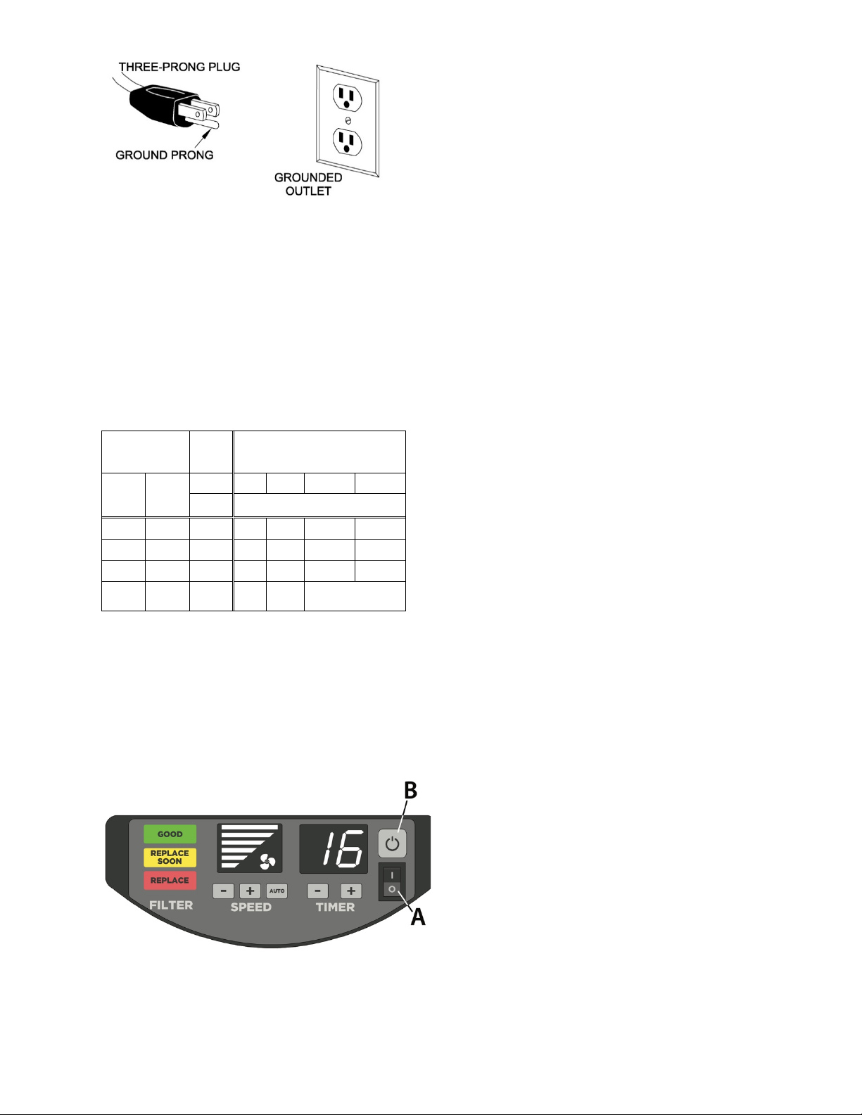
The AFS-850 Air Filtration System is prewired for
single phase, 120V power. It is provided with a plug
designed for use on a circuit with a grounded outlet
that looks like the one pictured in Figure 7-1.
It is recommended that the AFS-850 be connected
to a 15-amp circuit with a circuit breaker or fuse. If
fuses are used, they should be time-delay fuse
marked “D”. Local codes take precedence over
recommendations.
7.1 GROUNDING INSTRUCTIONS
1. All Grounded, Cord-connected Tools:
This machine must be grounded. In the event of a
malfunction or breakdown, grounding provides a
path of least resistance for electric current to reduce
the risk of electric shock. This tool is equipped with
an electric cord having an equipment-grounding
conductor and a grounding plug. The plug must be
plugged into a matching outlet that is properly
installed and grounded in accordance with all local
codes and ordinances.
Do not modify the plug provided - if it will not fit the
outlet, have the proper outlet installed by a qualified
electrician.
Improper connection of the equipment-grounding
conductor can result in a risk of electric shock. The
conductor with insulation having an outer surface
that is green with or without yellow stripes is the
equipment-grounding conductor. If repair or
replacement of the electric cord or plug is
necessary, do not connect the equipment-grounding
conductor to a live terminal.
Check with a qualified
electrician or service person if the grounding
instructions are not completely understood, or if
in doubt as to whether the tool is properly
grounded. Failure to comply may cause serious
or fatal injury.
Use only 3-wire extension cords that have 3-prong
grounding plugs and 3-pole receptacles that accept
the tool's plug.
Repair or replace damaged or worn cord
immediately.
2. Grounded, cord-connected tools intended for use
on a supply circuit having a nominal rating less than
150 volts:
This tool is intended for use on a circuit that has an
outlet that looks like the one illustrated in Figure 7-
1.

10
Figure 7-1
7.2 Extension Cords
The use of extension cords is discouraged. Try to
position machines within reach of the power source.
If an extension cord must be used, make sure it is
heavy enough to carry the current your product will
draw. An undersized cord will cause a drop in line
voltage resulting in loss of power and overheating.
Table 2 shows correct size to use depending on
cord length and nameplate ampere rating. If in
doubt, use the next heavier gauge. The smaller the
gauge number, the heavier the cord.
Ampere
Rating
Volts
Total length of cord in feet
More
Than
Not
More
Than
120
25
50
100
150
AWG
00
06
18
16
16
14
06
10
18
16
14
12
10
12
16
16
14
12
12
16
14
12
Not
Recommended
Extension Cord Recommendations
Table 2
8.0 Controls Functions
8.1 Control Panel Buttons
Figure 8-1
POWER ON/OFF SWITCH – A
The Power ON/OFF Switch (Fig. 8-1, A) is a rocker
switch on the control panel used to supply power to
the AFS electronic controls and thus the full AFS.
In the OFF position, AC power is disconnected from
the electronics. The AFS unit will not turn On.
In the ON position, AC power is connected to the
electronics. The electronics are powered On in a
STANDBY state awaiting user input via the ON/OFF
Button (B).
ON/OFF BUTTON – B
When the Power ON/OFF Switch (Fig. 8-1, A) is first
turned ON, power is supplied to the electronics and
the AFS unit is in the STANDBY state. All DISPLAYs
are off.
Each press of the ON/OFF Button (Fig. 8-1, B)
cycles the AFS unit between STANDBY and ON.
Pressing the ON/OFF Button once:
• AFS Unit goes to ON state.
• The TIMER DISPLAY is blank.
• The fan starts to run at speed 1.
• The SPEED DISPLAY shows 1 bar for speed 1.
• The FILTER DISPLAY will illuminate the filter
status.
Pressing the ON/OFF Button again does the
following:
• AFS unit goes to STANDBY state.
• All DISPLAYS are off, and the fan stops.
TIMER
The TIMER may be set in 1-hour increments from 1
to 16 hours. When the timer expires, the fan will stop
and the AFS will enter STANDBY state.
When the timer is not being used, the TIMER
Display will be blank and the AFS will run
continuously until the user changes the settings or
stops the AFS.
To activate the TIMER, press the TIMER + Button.
• The TIMER DISPLAY changes from blank to
display flashing “1”. This is 1 hour.
• Pressing the TIMER + Button again will
increase the number by 1 each time the TIMER
+ Button is pressed. Up to a maximum of 16
hours.
• Pressing the TIMER – Button will decrease the
number by 1 each time the TIMER - Button is
pressed. Down to a blank display turning the
TIMER Off and running the AFS continuously.
• If the display is already set and showing an hour
time value, then pressing the TIMER + or –

11
Button will add or subtract time from the already
set value.
• When the TIMER + or – Button have been
pressed, the number on the TIMER Display will
flash for 1 second and then show steady ON.
Steady ON indicates the TIMER is set and the
countdown has begun.
• Pressing and holding either the TIMER + or –
Button (2 seconds) will advance the count
quickly (changing every 0.2 seconds) until the
button is released.
FAN SPEED ADJUSTMENT
The SPEED Display uses illuminated bars to
indicate which speed level is active. The upper most
illuminated bar is the current speed setting. The bars
not lit are still available to increase fan speed if
desired.
Air flow at each fan SPEED setting is as follows:
Fan Speed Setting
CFM
1 (1-bar)
450 ±10%
2 (2-bars)
530 ±10%
3 (3-bars)
610 ±10%
4 (4-bars)
690 ±10%
5 (5-bars)
770 ±10%
6 (6-bars)
850 ±10%
Table 3
When the AFS is turned ON, the fan will start and
run at SPEED 1 until changed by the user. The
SPEED Display will show 1 bar.
• Pressing the SPEED + Button will increase the
fan speed.
• Pressing the SPEED – Button will decrease the
fan speed.
AUTOMATIC MODE
NOTE: For best performance in AUTO Mode, allow
adequate air flow to the sensor on the front of the
unit (see Fig. 8-3).
Figure 8-3
When the AUTO Button is pressed, the AUTO
Button is illuminated, and the AFS is operating in
AUTO Mode.
In AUTO Mode, the integrated sensor detects the air
quality and adjusts the fan speed accordingly.
Thereby reducing energy consumption when air
quality is good and increasing the fan speed when
dust is present.
• Pressing either the SPEED + or – Button will
deactivate AUTO Mode and return to manual
mode.
NOTE: In AUTO Mode the unit may require
several minutes to return to fan speed 1 once
dust is detected. The unit intentionally ramps
down slowly to ensure good shop air quality.
FILTER STATUS INDICATOR
The FILTER Status Indicators are located on the
control panel and are there to indicate the condition
of the filters.
"GOOD" indicates that the filters are clean enough
to provide effective filtration.
"REPLACE SOON" indicates that the filters are
becoming clogged, reducing the unit’s ability to
effectively filter the shop air, and therefore will need
to be cleaned/replaced soon.
“REPLACE" indicates that the filter is clogged to the
point that it needs to be cleaned or replaced.

12
9.0 Operation
NOTE: The Air Filtration Unit is designed to remove
airborne, non-metallic dust particles; it is not
designed to take the place of a dust collection
system.
Larger particles are trapped by the Pre-Filter.
Smaller particles are stopped by the Canister Filter.
The clean air is then exhausted through the
impellers at the top of the machine.
IMPORTANT: Do not block the top of the Fan Head
or any portion of the perforated Steel Barrel.
Normal operation:
• Place Power On/Off Switch to ON.
• Press the On/Off Button.
• Set the SPEED as desired or select AUTO.
• If desired, set the TIMER to automatically turn
off at a later time.
• At the end of the day or shift, or if leaving for an
extended period of time, press the On/Off
Button to stop the fan.
• If leaving for a longer period of time, such as a
weekend or vacation, turn the Power On/Off
Switch to Off.
10.0 User Maintenance
Always disconnect power to
the machine before performing maintenance.
Failure to do this may result in serious personal
injury.
10.1 Changing the Filters
To reduce the risk of injury,
disconnect the air filtration system from the
power source (unplug) before servicing or
changing filters. Failure to comply may cause
serious injury!
There are two filters that need to be changed or
cleaned, the Pre-Filter and the Canister Filter.
Filter life will vary depending on the amount of usage
and the environment of your shop. Clogged filters
will reduce the amount of air circulation.
1. Unplug the machine’s power cord from the
electrical outlet.
2. Place a foot on the Base, grasp the Circle
Handle, and turn Fan Head counterclockwise to
unlock (see Figure 10-1).
Figure 10-1
3. Lift the Fan Head straight up set it aside.
4. Lift the Pre-Filter/Canister Filter out of the Steel
Barrel (see Figure 10-2).
Figure 10-2

13
5. Remove the Pre-Filter from the Canister Filter
(see Figure 10-3).
Figure 10-3
6. Either clean the Pre-Filter or replace it with a
new filter. The Pre-Filter can be cleaned with
water. If cleaning, follow the instructions in
10.2.1 Washable Pre-Filter.
7. Either clean the Canister Filter or replace it with
a new filter. If cleaning, do not use water. Follow
the instructions in 10.2.2 Cleaning Canister
Filter.
8. If using a new Canister Filter, remove any
protective wrapping.
9. Install new or cleaned Pre-Filter around the new
or cleaned Canister Filter. Place filters into the
Steel Barrel.
10. Place the Fan Head back onto the Steel Barrel.
Place a foot on the base and slightly rotate the
Fan Head left and right until it drops into place
on the mounting studs located around the top of
the Steel Barrel. At this point, rotate the Fan
Head clockwise to lock it into place.
11. Reconnect the power cord to an electrical
outlet.
Replacement Filters:
NOTE: JET brand filters are recommended for best
performance.
AFS850-008 ........ Pre-Filter
AFS850-016 ........ Canister Filter
AFS850-CF ......... Charcoal Filter (optional accessory)
10.2 Cleaning the Filters
To reduce the risk of injury,
disconnect the air filtration system from the
power source (unplug) before servicing or
changing filters. Failure to comply may cause
serious injury!
This AFS is designed to remove airborne non-
metallic dust particles from the air. Cleaning is about
removing those particles from the filter in the
opposite direction from which they came.
Clean both the Pre-Filter and the Canister Filter at
the same time. Whether using the Filter Status
Indicator or a visual inspection, both filters should be
cleaned to restore as much filtration ability as
possible.
Remove the filters from the AFS unit as described
in 10.1 Changing the Filters.
10.2.1 Washable Pre-Filter
The Pre-Filter (p/n AFS850-008) is washable and
must be dry before returning to service.
• Using a hose and spray nozzle with normal tap
water pressure, spray the filter from the inside
out. Opposite the operating air flow. This will
rinse the larger loose particles out of the filter.
• Mix a mild detergent and water mixture (soap)
such as dish soap. Mix a drop or two of dish
soap and water into a spray bottle. If using a
commercial electrostatic detergent, follow the
label instructions.
• Spray the soap onto the entire filter until fully
covered.
• Allow the soap to soak 1 to 2 minutes on the
filter but do not allow the soap to dry. This will
create a sticky film that is difficult to remove.
• Thoroughly rinse the soap out of the Pre-Filter.
• Allow all excess water to drain off the filter.
While the filter does not need to be absolutely
dry, do not return to service if water is dripping
or droplets are still visible.
• Low pressure compressed air may be used to
remove any remaining water from the filter.
10.2.2 Cleaning Canister Filter
The Canister Filter (p/n AFS850-016) is a dry filter
and should not get wet. Clean the filter using a
vacuum with a brush attachment on the vacuum
hose.
• Lightly brush the vacuum brush nozzle over the
outside side of the filter. The brush will help
dislodge the particles which will then be
removed by the vacuum.
• Make several passes moving in line with the
pleats of the filter.

14
• Visually inspect the filter while cleaning. If the
filter material is worn, torn, or coming apart from
the frame, it must be replaced.
10.4 Cleaning Sensors
Dust may accumulate on the sensor (see Fig. 8-3)
and affect the performance in AUTO mode. Clean
the Sensor with a dry cloth or compressed air.
10.5 Sensor Replacement
The AFS unit ships from the factory with the sensor
and control board calibrated and ready to use. In the
event the sensor should need replacing, follow
these instructions to calibrate the new sensor:
1. With the Power ON/OFF Switch (Fig. 10-4, A)
in the OFF position, press and hold the Timer-
DN(-) and Timer-UP(+) buttons simultaneously
and switch the Power ON/OFF Switch to the ON
position to enter the environment value setting
mode.
2. The screen flashes and displays “- -", the
calibration is completed when the detected
value is stable (- - disappears), and then returns
to the standby state.
Figure 10-4
10.6 Control Board Replacement
In the event the control board needs replacing,
follow the steps in Section 10.5 to calibrate the
sensor with the new control board.

15
11.0 Troubleshooting
Table 4
Symptom
Probable Cause
Remedy
AFS will not start
Power ON/OFF Switch in the OFF
position
Move Power ON/OFF Switch to the ON
position.
No incoming power
Check plug connection
Verify there is power at the outlet, check
breaker or fuse panel.
Low voltage
Request voltage check form power
company and correct low voltage
condition.
Power cord damaged
Replace power cord.
Control button or PCBA malfunction
Contact JET customer service.
Excessive vibration
Loose frame, parts, or fasteners
Inspect and tighten as needed.
Impeller imbalance
Clean impeller (do not use solvents).
If imbalance still occurs, replace impeller.
Motor imbalance
Have motor tested by qualified personnel;
replace if needed.
Unit not working
efficiently; not cleaning
air.
Filter not installed properly
Reinstall filter.
Blocked air flow
Inspect filter; replace if clogged
remove blockage.
Controls on unit not
working
Control button or PCBA malfunction
Contact JET customer service.
Timer screen displays
numbers / letters other
than a countdown timer
If screen displays A8, filter is not installed
Install filter.
Control may be in factory set-up mode
Move Power ON/OFF Switch to the OFF
position. Wait 30 seconds, then switch
back to ON. Then press the On/Off
Button.
Loose connection on the control board
Move Power ON/OFF Switch to the OFF
position and unplug the unit. Check the
electrical connections to the control board
to ensure they are all seated properly.
Control button or PCBA malfunction
Replace control board.
Contact JET customer service.
*Warning: Some remedies may require a qualified electrician.

16
12.0 Replacement Parts
Replacement parts are listed on the following pages. To order parts or reach our service department, call 1-800-
274-6848 Monday through Friday, 8:00 a.m. to 5:00 p.m. CST. Having the Model Number and Serial Number of
your machine available when you call will allow us to serve you quickly and accurately.
12.1.1 AFS-850 Unit – Exploded View

17
12.1.2 AFS-850 Unit – Parts List
Index No Part No Description Size Qty
1 ................ AFS850-001 .............. Mesh guard .............................................................. ..................................... 1
2 ................ AFS850-002 .............. Motor ....................................................................... ...................................... 1
3 ................ AFS850-003 .............. Fan body .................................................................. ...................................... 1
4 ................ AFS850-004 .............. Fan blade ................................................................. ...................................... 1
5 ................ AFS850-005 .............. Control module ........................................................ ...................................... 1
6 ................ AFS850-DMA ............ Display module assembly ........................................ ...................................... 1
7 ................ AFS850-PLCA ........... Panel lower cover assembly .................................... ...................................... 1
8 ................ AFS850-008 .............. Pre-filter ................................................................... ...................................... 1
9 ................ AFS850-PC ............... Power cord .............................................................. 15-feet ........................... 1
9-1 ............. AFS1000C-019 ......... Cable gland ............................................................. ...................................... 1
10 .............. AFS850-010 .............. Reinforcing metal bracket ........................................ ...................................... 1
11 .............. AFS850-011 .............. Circle handle ............................................................ ...................................... 1
12 .............. AFS850-012 .............. Handle support ........................................................ ...................................... 4
13 .............. AFS850-013 .............. Handle support base ............................................... ...................................... 4
14 .............. AFS850-014 .............. Tube plugs ............................................................... ...................................... 4
15 .............. AFS850-015 .............. Deflector .................................................................. ...................................... 1
15-1 ........... AFS850-MS ............... Micro switch ............................................................. ...................................... 1
16 .............. AFS850-016 .............. Filter, canister .......................................................... ...................................... 1
17 .............. AFS850-017 .............. Rubber gasket ......................................................... ...................................... 1
18 .............. AFS850-018 .............. Steel barrel .............................................................. ...................................... 1
19 .............. AFS850-019 .............. Plastic base ............................................................. ...................................... 1
20 .............. AFS850-PBCA .......... Plastic base cover assembly ................................... ...................................... 1
21 .............. JET-56B .................... JET stripe (5.12" x 6.10") ......................................... ...................................... 1
22 .............. AFS850-022 .............. Warning label ........................................................... ...................................... 1
23 .............. AFS850-MD .............. Model decal, AFS-850 ............................................. ...................................... 1
24 .............. AFS1000C-025 ......... Flat head screw (tapping screw) .............................. M4 x 10 ......................... 4
25 .............. AFS1000C-DM8 ........ Screw, pan head, Phillips (tapping screw) ............... M3 x 10 ......................... 4
26 .............. AFS1000C-025 ......... Flat head screw (tapping screw) .............................. M4 x 10 ......................... 4
27 .............. AFS1000C-032 ......... Screw, flanged, hex head, Phillips ........................... M6 x 10 ......................... 4
28 .............. AFS850-028 .............. O-rings ..................................................................... Φ6 x Φ12 ...................... 4
29 .............. AFS850-029 .............. Countersunk socket head screw ............................. M6 x 85 ......................... 4
30 .............. AFS1000C-025 ......... Flat head screw (tapping screw) .............................. M4 x 10 ......................... 6
31 .............. AFS850-031 .............. Round head self-tapping screws (drill tail) ............... M4 x 10 ......................... 4
32 .............. AFS850-032 .............. Large flat head, Phillips, self-tapping screw ............ M4 x 14 ....................... 10
33 .............. AFS850-033 .............. Motor label (not shown) ........................................... ...................................... 1
34 .............. AFS850-034 .............. ID label (not shown) ................................................. ...................................... 1
35 .............. AFS850-035 .............. Display cable (not shown) ....................................... ...................................... 1
36 .............. AFS850-036 .............. Dust sensor cable (not shown) ................................ ...................................... 1
Optional Accessories:
.................. AFS850-CF ............... Charcoal filter

18
12.2.1 Display Module Assembly – Exploded View
12.2.2 Display Module Assembly – Parts List
Index No Part No Description Size Qty
6 ................ AFS850-DMA ............ Display module assembly ........................................ ...................................... 1
6-1 ............. AFS1000C-DM1 ........ AC power switch ...................................................... ...................................... 1
6-2 ............. AFS850-DM2 ............ Display label ............................................................ ...................................... 1
6-3 ............. AFS850-DM3 ............ Auto button .............................................................. ...................................... 1
6-4 ............. AFS850-DM4 ............ Display cover ........................................................... ...................................... 1
6-5 ............. AFS850-DM5 ............ Display PCB ............................................................ ...................................... 1
6-6 ............. AFS1000C-DM6 ........ Screw, pan head, Phillips (tapping screw) ............... M3 x 6 ........................... 6
12.3.1 Lower Panel Cover Assembly – Exploded View
12.3.2 Lower Panel Cover Assembly – Parts List
Index No Part No Description Size Qty
7 ................ AFS850-PLCA ........... Panel lower cover assembly .................................... ...................................... 1
7-1 ............. AFS850-PLC1 ........... Panel lower cover .................................................... ...................................... 1
7-2 ............. AFS850-PLC2 ........... Dust sensor fan ....................................................... ...................................... 1
7-3 ............. AFS1000C-014 ......... Dust sensor ............................................................. ...................................... 1
7-4 ............. AFS850-PLC4 ........... Screw, round head, Phillips (tapping screw) ........... M3 x 8 ........................... 4

19
12.4.1 Plastic Base Cover Assembly – Exploded View
12.4.2 Plastic Base Cover Assembly – Parts List
Index No Part No Description Size Qty
20 .............. AFS850-PBCA .......... Plastic base cover assembly ................................... ...................................... 1
20-1 ........... AFS850-PBC1 ........... Plastic base cover ................................................... ...................................... 1
20-2 ........... AFS850-PBC2 ........... Counterweights ........................................................ ...................................... 1
20-3 ........... AFS850-PBC3 ........... Hex nylon nut ........................................................... ...................................... 1
20-4 ........... AFS850-PBC4 ........... Screw, flanged hex head, Phillips ............................ M6 x 16 ......................... 1

20
13.0 Electrical Connections - 115V
This manual suits for next models
1
Table of contents
Other Jet Air Cleaner manuals