GB - ENGLISH
Operating Instructions
Dear Customer,
Many thanks for the confidence you have shown in us with the purchase of your new JET-machine. This manual has been
prepared for the owner and operators of a JET 719-A mortiser to promote safety during installation, operation and maintenance
procedures. Please read and understand the information contained in these operating instructions and the accompanying
documents. To obtain maximum life and efficiency from your machine, and to use the machine safely, read this manual thoroughly
and follow instructions carefully.
…Table of Contents
1. Declaration of conformity
2. JET Warranty
3. Safety
Authorized use
General safety notes
Remaining hazards
4. Machine specifications
Technical data
Noise emission
Contents of delivery
5. Transport and start up
Transport and installation
Assembly
Mains connection
Dust collection
Starting operation
6. Machine operation
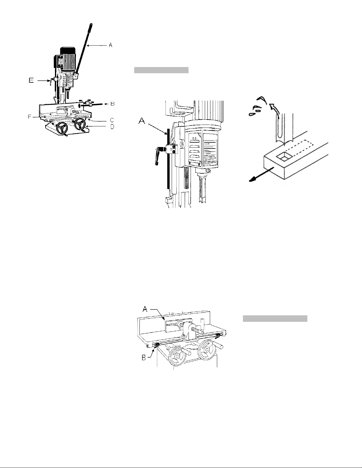
7. Setup and adjustments
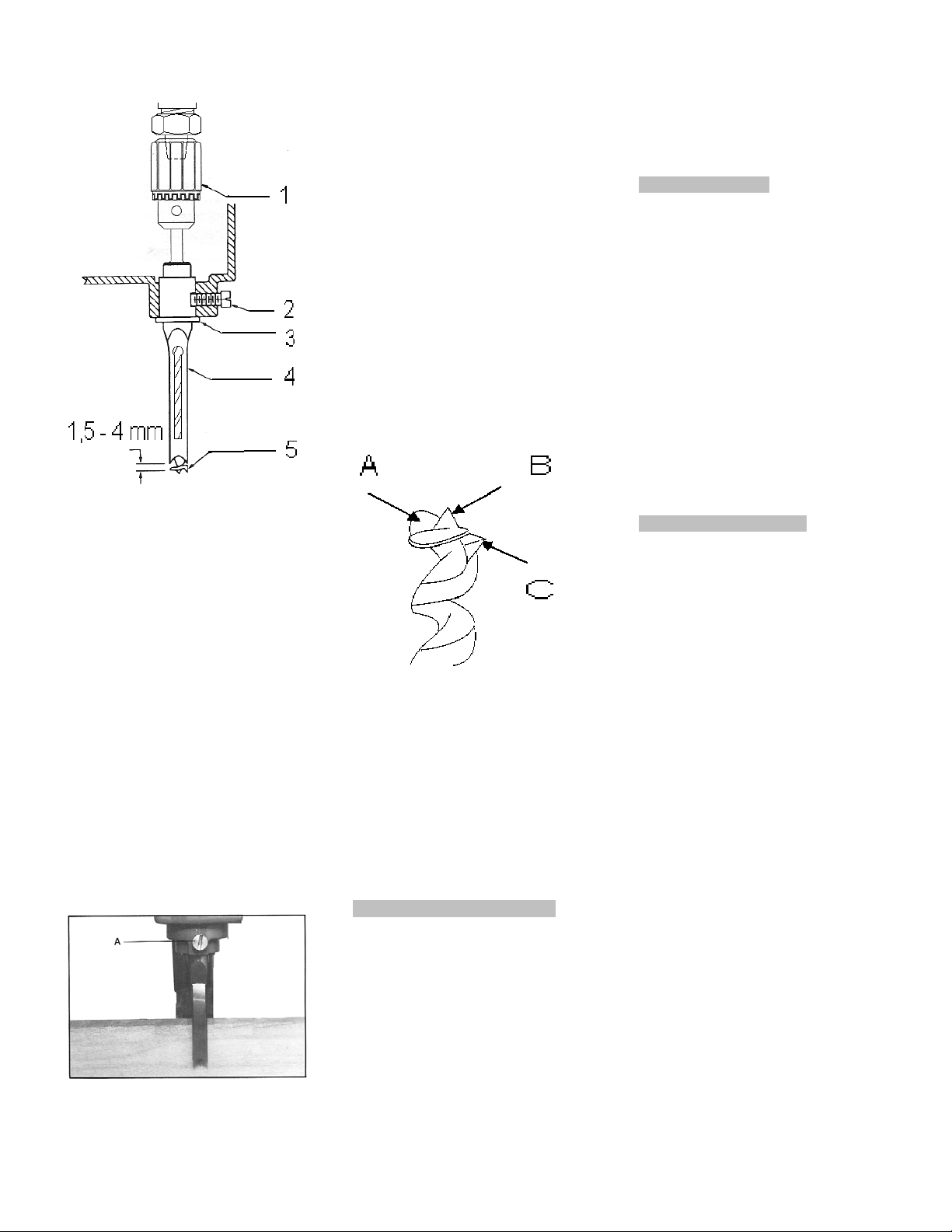
Installing chisel and bit
Sharpening chisel and bit
8. Maintenance and inspection
9. Trouble shooting
10. Available accessories
1. Declaration of conformity
On our own responsibility we hereby
declare that this product complies with
the regulations* listed on page 2.
Designed in consideration with the
standards**.
2. JET Group Warranty
The JET Group makes every effort to
assure that its products meet high
quality and durability standards and
warrants to the original retail
consumer/purchaser of our products
that each product be free from defects
in materials and workmanship as
follows:
2 YEAR LIMITED WARRANTY ON
ALL PRODUCTS UNLESS
SPECIFIED OTHERWISE.
This Warranty does not apply to
defects due to directly or indirectly
misuse, abuse, negligence or
accidents, normal wear-and-tear,
repair or alterations outside our
facilities, or to a lack of maintenance.
The Jet group limits all implied
warranties to the period specified
above, from the date the product was
purchased at retail.
To take advantage of this warranty, the
product or part must be returned for
examination, postage prepaid, to an
authorized repair station designated by
our office.
Proof of purchase date and an
explanation of the complaint must
accompany the merchandise.
If our inspection discloses a defect, we
will either repair or replace the product,
or refund the purchase price if we
cannot readily and quickly provide a
repair or replacement, if you are willing
to accept a refund.
We will return repaired product or
replacement at JET’S expense, but if it
is determined there is no defect, or that
the defect resulted from causes not
within the scope of JET’S warranty,
then the user must bear the cost of
storing and returning the product.
The JET Group reserves the right to
make alterations to parts, fittings, and
accessory equipment which they may
deem necessary for any reason
whatsoever.
3. Safety
3.1 Authorized use
This mortiser is designed for mortising
wood and similar materials only.
Machining of other materials is not
permitted and may be carried out in
specific cases only after consulting
with the manufacturer.
The proper use also includes
compliance with the operating and
maintenance instructions given in this
manual.
The machine must be operated only by
persons familiar with its operation and
maintenance and who are familiar with
its hazards.
The required minimum age must be
observed.
The machine must only be used in a
technically perfect condition.
When working on the machine, all
safety mechanisms and covers must
be mounted.
In addition to the safety requirements
contained in these operating
instructions and your country’s
applicable regulations, you should
observe the generally recognized
technical rules concerning the
operation of woodworking machines.
Any other use exceeds authorization.
In the event of unauthorized use of the
machine, the manufacturer renounces
all liability and the responsibility is
transferred exclusively to the operator.
3.2 General safety notes
Woodworking machines can be
dangerous if not used properly.
Therefore the appropriate general
technical rules as well as the following
notes must be observed.
Read and understand the entire
instruction manual before attempting
assembly or operation.
Keep this operating instruction close
by the machine, protected from dirt
and humidity, and pass it over to the
new owner if you part with the tool.
No changes to the machine may be
made.
Daily inspect the function and
existence of the safety appliances
before you start the machine.
Do not attempt operation in this case,
protect the machine by unplugging the
power cord.