Makita 7104L Manual

Model No.
Description
PRODUCT
CONCEPT AND MAIN APPLICATIONS
Specifications
Standard equipment
Note: The standard equipment for the tool shown above may differ from country to country.
P 1 / 8
7104L
Chain Mortiser
Based on the current model 7104L, its specifications have been upgraded
to meet the European standards. The front cover has been added
to enclose the cutter chain. Some electrical parts have been changed to
comply with the electromagnetic compatibility-requirement.
This tool is ideal for making mortises and notches quickly. Pivoting chain
bar enables an opearator to make a 130mm long rectangular hole in
three cutting processes without reclamping a workpiece.
Except for Europe, Australia and New Zealand, the current specifications
have been continued. Dimensions: mm
Width (W)
Height (H)
Length (L) 512 (20-1/8)
298 (11-3/4)
513 (20-1/4)
Max clamp capacity
Protection against electric shock
Max mortise width transverse
longitudinal
No load speed: min-1=rpm 3,200
Chain blade: mm (") France: 30 (1-3/16)
Other countries: 16.5 (5/8)
130 (5-1/8)
France: 45 (1-3/4)
Other countries: 31.5 (1-1/4)
308 (12-1/8)
155 (6-1/8)
Grounding
Net weight: kg (")
Power supply cord: m (ft) 5.0 (16.4)
17 (37.5)
Max mortise depth
Chain blade 16.5mm (5/8")* ...... 1 pc
Wrench 13-17 ............................. 1 pc
Oil vessel ..................................... 1 pc
Sharpening holder ass'y
Cutter chain: 15mm (9/16"), 16.5mm (5/8"), 18mm (11/16"), 21mm (13/16") and 24mm (15/16").
**30mm (1-3/16")
**Sprocket 4 for 30mm cutter chain
**Chain bar ass'y for 30mm cutter chain
(**marks: These accessories should be used at the same time. )
*France: 30mm (1-3/16")
L
W
H
Capacity:
mm (")
TECHNICAL INFORMATION
Optional accessories
Continuous Rating (W)
Voltage (V) Cycle (Hz) Input Output Max. Output(W)
110
230
240
10
5.2
5
50/60
50/60
50/60
1,050
1,140
1,140
680
780
780
1,300
1,500
1,500
Current (A)

P 2 / 8
Repair
[2] LUBRICATION
[1] NECESSARY REPAIRING TOOLS
CAUTION: For safety before repair/maintenance;
1)Unplug machine. 2)Remove cutter chain, chain bar, Hex. bolt M10 and Washers.
Code No.
1R045 Gear extractor, large
1R275
Description Use for
Type 94 field insert jig
1R308 Spring pin extractor 4.0
1R309 Spring pin extractor 5.0
Removing Sprocket 4
Removing 4.0mm diameter Spring pins
Removing 5.0mm diameter Spring pins
Removing 6.0mm diameter Spring pins
1R310 Spring pin extractor 6.0
HoldingSprocket 4 to unscrew Hex nut M10
See Fig. 1.
1. Apply 10g of Makita grease N No.1 for the teeth of Helical gear 47 and put some amount of Makita grease N No.1 on
the rubbing surfaces of Motor housing complete and Rotor holder for their smooth pivot action. Refer to marks.
2. Put a little amount of machine oil on Spring pin 5-40, two slide poles of Base complete, the threads of M14 Screw,
inside of Ring 9 and both sides of Sleeve 9 near Clamp lever, the inside of Sleeve 9 near Lever B complete, Slide bar
and Guide pole. Refer to marks.
3. Put a little amount of adhesive on the threads of M6x12 + Countersunk head screw for setting Ball bearing 1008LL to
Chain bar. Refer to marks.
Fig. 1
Ring 9: Inside
Sleeve 9: Inside and outside
Clamp lever
Guide pole
Slide bar
Lever B complete
Sleeve 9: Inside
Chain bar
Spring pin 5-40
Rotor holder
Helical gear 47
Slide poles of Base complete
Screw M14
Motor housing
complete
Ball bearing
1008LL
+ Countersunk
head screw M6x12
Makita grease N No.1 (Part No. 042017-7A, 2.5kg/set)
Machine oil
Adhesive: 0.12g Three bond 1342
(Makita Neji lock super TB1342:
Part No. 045017-6A)

P 3 / 8
Repair
[3] Repairing Motor Section
[3]-1. Disassembling Motor Section
[3]-2. Reassembling Motor Section
Armature and Field can be replaced without disassembling Gear housing section.
Remove Carbon brushes from the machine.
Motor housing complete can turn freely by separating four M5x80 pan head screws from the machine.
However, the last one is difficult to be unscrewed because the tensile force of Tension spring 20 affects it through Chain
bar holder and Rotor holder. Therefore, push Handle to counterclockwise direction as mentioned in Fig. 1 to remove the
last M5x80 pan head screw.
Next, Turning Motor housing complete clockwise as shown in Fig. 2 so that the tensile force of Tension spring 20 can be
removed.
Four Pan head screws M5x80
Push the Handle
in the direction of
arrow.
Handle (switch installation side)
Chain bar holder
Spring pin 5-12 for the stopper
of Tension spring 20
Hook of Rotor holder
for Tension spring 20
Hook of Rotor holder
for Tension spring 20
Spring pin
extractor 5.0
Motor
housing
Rotor holder
Tension
Spring 20
Fig. 1
Fig. 4 Fig. 5
Fig. 3
Fig. 2
Turn the Motor
housing complete
in the direction of
arrow.
Strike one end of Spring pin 5-12 using Spring pin extractor 5.0
(Makita part No. 1R309) and plastic hammer as shown in Fig. 3
until the other end comes out of the hook of Rotor holder.
And then, pull out the Spring pin 5-12 from the opposite side
using pliers. Pull out Motor housing complete backward while
turning it. Move on to the step for Motor replacement.
One end of Spring pin 5-12
One end of Tension Spring 20
The other end of Tension Spring 20
Grip holder L Press Motor housing with knee. Check these flat
areas is parallel
to the ground.
Chain bar holder
should be vertical
against ground.
Plastic hammer
Perform the disassembling procedure in reverse of the assembling steps.
The reassembling work can be successfully performed even if Tension spring 20 shrinks to the original size.
Drive Spring pin 5-20 into the hole of Rotor holder's hook upward from the bottom so that the upper end protrudes by 4mm
for the stopper of Tension spring 20. Install Armature from Chain bar holder side. It is useful as a guide when Motor
housing complete is installed.
Hook one end of Tension spring 20 in the hole of Grip holder L as shown in Fig. 4 after inserting Motor housing section in
Rotor holder. Chain cover should be vertical against ground. And both Motor housing and Rotor holder should be paralleled
to the ground while pulling Tension spring 20 using Handle as described in Fig. 5. At this time, while pressing Motor
housing section with knee, tighten four M5x80 pan head screws. This is to prevent the Motor housing section from slipping
off.
Motor housing
Spring pin 5-12 for the stopper
of Tension spring 20
Push Handle to
the direction of
arrow.

P 4 / 8
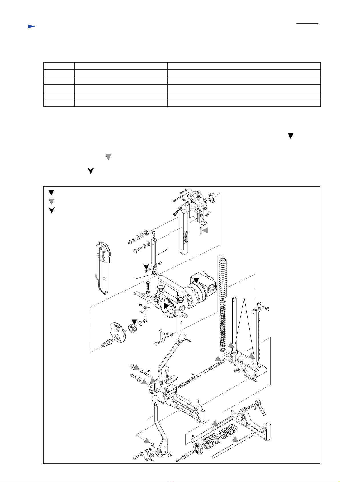
[4] Disassembling Gear Section
[5] Disassembling Vice Element
Note: Gear section can be replaced without disassembling Motor section.
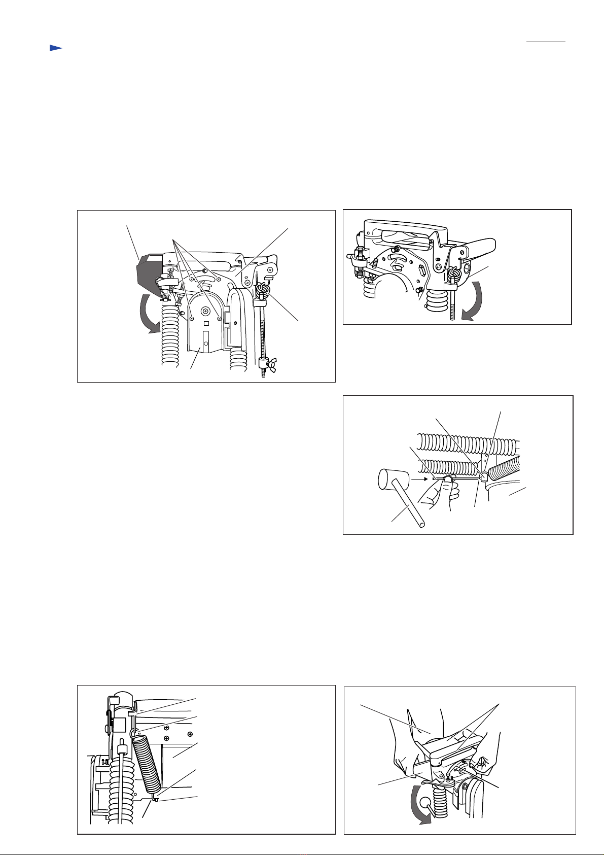
Vice element can be pulled out only by loosening Lever 98 ass'y as illustrated in Fig. 7. If chips attach in the Compression
spring 48 and Compression spring 36, the chips make the clamp operation worse. Therefore, disassemble and clean them.
Loosen M6x35 Pan head screw to remove the Compression springs using cordless impact driver with phillips bit No.3 as
mentioned in Fig. 8 while holding Vice shoe so as not to jump by the reaction force of the Compression springs.
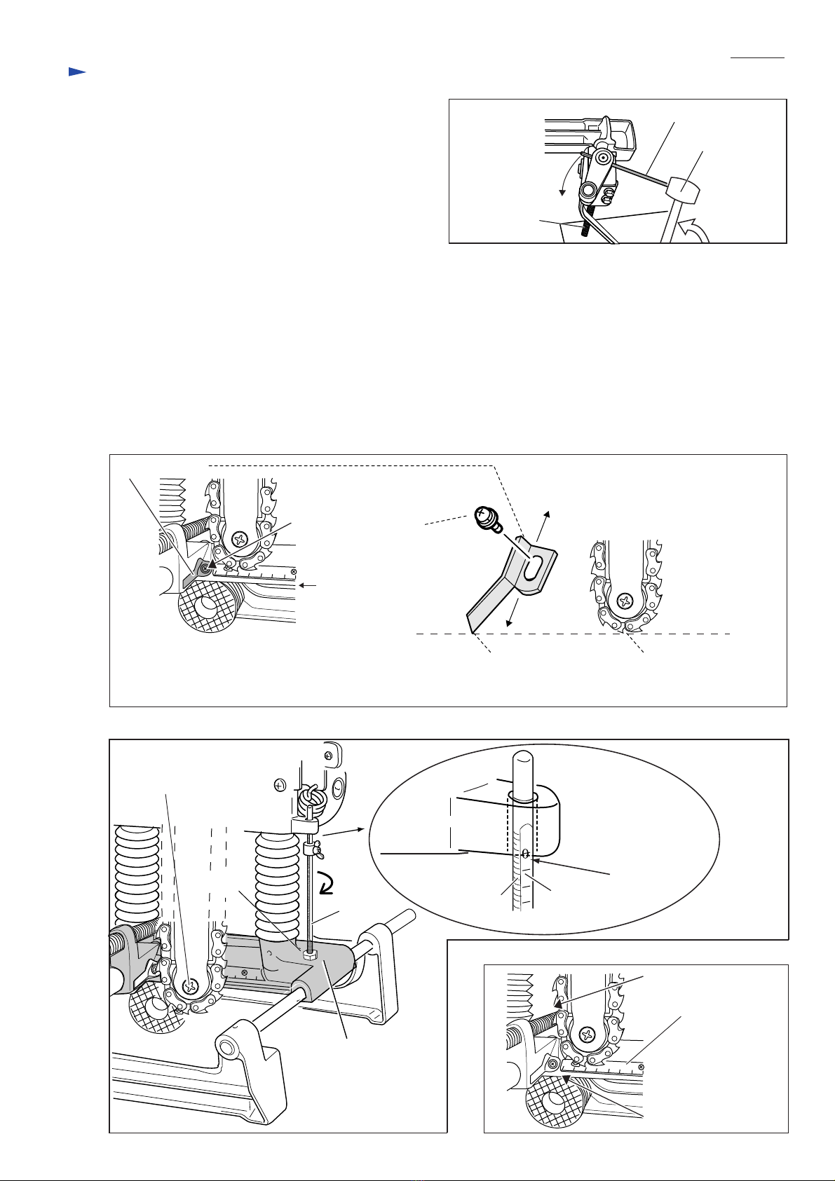
[6] Disassembling Front Vice
Main body including Base complete on vice section can be removed backward from
the Vice section in the following steps.
1) Disassemble Vice element in accordance with the above procedure.
2) Forward the main body to the edge of Screw M4 by turning Knob 20 as shown in
Fig. 9 .
Loosen two Levers in the direction of arrows as illustrated in Fig. 10.
Push one end of Spring pin at the right side of Lever B complete using Spring pin
extractor 4.0 (Makita part No. 1R308) and plastic hammer.
Consequently, Pin 9 and some components can be separated as described in Fig. 11.
Fig. 6
Fig. 9
Fig. 8Fig. 7
Fig. 10 Fig. 11
Remove Spring washer 10, Flat washer 10 and Ring 15 from Spindle by hand.
Remove Sprocket 4 from tool by hand. If it is stuck on the spindle firmly, use Gear extractor Large (Makita part No. 1R045).
Strike the reverse side of Chain bar holder using plastic hammer, so Gear housing can be separated from Chain bar holder.
The connecting parts of Chain bar holder and Gear housing are three Spring pins 6-24 only.
Remove gear section from Gear housing, and then tap the gear section on the table to separate Helical gear 47 from the
other components of the gear section.
Loosen M10 Hex. nut using Box
wrench 17.
Type 94 Field insert jig
Sprocket 4 Wall of Chain
bar holder
Compression spring 48 and
Compression spring 36 (inside)
Cordless impact drive with phillips
bit No.3
Vice shoe
Vice element Vice element
Lever 98 assembly
Lever
(Lever B complete)
Lever (Clamp)
Spring pin 4-20
(left side)
Pin 9Flat washer 9
Spring pin 4-20 (right side)
Flat washer 9
Sleeve 9 (inside)
Plastic hammer
Sleeve 9
Lever B complete
Spring pin extractor 4.0
Lever B complete
Screw M14
Vice section
Knob 20
Repair
Remove four M5x80 pan head screws in the front of the tool in the same manner
described in Repairing Motor Section.
To release the tensile force of Tension spring 20, Turn the Motor housing clockwise.
The tension spring 20 will return to the original size. Consequently, Motor housing
complete can be easily removed.
Pull out Chain bar holder to your side from the front of tool while turning it.
Insert Type 94 Field insert jig (Makita part No. 1R275) between Sprocket 4 and the
wall of Chain bar holder in order not to revolve Spindle fixed with the Sprocket 4
as shown in Fig.6. Loosen M10 Hex. nut using Box wrench 17 or Wrench 13-17.

Hex. nut M8
P 5 / 8
Fig. 12
Fig. 13
Fig. 14
Spring pin extractor 4.0
Plastic hammer
Spring pin 4x20
M14 Screw
Table
When removing M14 Screw from the front vice section;
1) Press the end of M4 Screw against table to compress
Compression spring 10.
2) At the same time, push out 4-20Spring pin in M14 Screw
using Spring pin extractor 4.0 (Makita part No. 1R308).
See Fig. 12.
[7] Adjustment
Note: The following information applies to the products including 16.5mm cutter chain as the standard accessory.
Front edge of Indication
plate (yellow)
Front end of 16.5mm
cutter chain
Pan head screw M4x8
Bottom of Base
complete
Indication plate Slide Indication plate
backward or forward.
1) Fix an yellow colored Indication plate to Base complete with M4x8 pan head screw as shown in Fig. 13 after aligning
the front edge of the Indication plate with front end of 16.5mm cutter chain.
2) When aligning the center of + Countersunk head screw M6x12 with the bottom of Base complete, drive Stopper pole
into the Base complete by hand in order to adjust the height of Rotor holder at ZERO position on Stopper pole as
shown in Fig. 14. After positioning it, tighten M8 Hex. nut onto the hole of Base complete firmly using Wrench.
Note: Face the gauge of Stopper pole to outside before tihgtening M8 Hex. nut.
3) Align the left end of Scale plate with the left end of the cutter chain by resetting the scale plate on the Base complete.
See Fig. 15.
0
245
6
5
6
8
Fig. 15
Left end of 16.5mm
cutter chain
Left end of Scale plate
Scale plate
0
245
6
Stopper pole
Base complete
Center of + Countersunk
head screw M6x12
Gauge of the Stopper
pole
"ZERO" mark
Repair
Threads of the
Stopper pole
Rotor holder

P 6 / 8
4) Refer to Fig. 16, Fig. 17, Fig. 18 and Fig. 19.
Precisely adjust M8x44 Hex. bolts and Stopper to make a rectangular hole with the same size into the wooden workpiece
as illustrated in Fig. 20. When the machine with 16.5mm cutter chain is used, Fig. 20 shows the cutting size preset in
Makita plant. Meanwhile, if preferring to make a 30mm long rectangular hole, adjust M8x44 Hex. bolt for No. 2 set
position to lean Chain bar assembly to the limit.
5) Adjust the tension of 16.5mm cutter chain. When there is a clearance of
approx. 5 up to 6mm between the chain bar and the cutter chain, the tension
on the cutter chain is adequate. See Fig. 21.
Note: Do not touch the cutting edges of the cutter chain when pulling it.
6) Adjust the clearance between Chain bar holder and Rotor holder so that
Chain bar ass'y can be tilted smoothly without stuck by moving the tips of
three M5X16 Hex. bolts backward and forward.
Fig. 20
Fig. 21
Fig. 16
Fig. 19
Approx. 52mm
90mm
16.5mm 30mm
1. Cutting by a single stroke
at vertical position. 2. Cutting by each stroke at:
1)vertical position and No.1 set position when Lever B complete is shifted forward.
2)vertical position and No.1 set position after Lever B complete is shifted backward.
Total four strokes
3. Cutting by each stroke at:
1)vertical position, No.1 set position and No. 2 set position when Lever B complete is shifted forward.
2)vertical position, No.1 set position and No. 2 set position after Lever B complete is shifted backward.
Total six strokes
120mm
Stopper
Original position (vertical against ground)
Lever B complete
<Forward>
<Backward>
If the travel distance is set at 13.5mm by shifting Lever B complete forward,
a 16.5mm wide rectangular hole can be cut in a single stroke.
Total 30.0mm wide holes can be made after shifting Lever B complete backward
and repeating a single stroke.
13.5mm
Tip of M8x44 Hex. bolt for No.1 set position
is hooked on rib of Rotor holder directly. It is
No.1 set position of Chain bar.
5 up to 6mm
Cutter chainChain bar
Lever C
Lever C is hooked on rib of Rotor holder
directly as below. It is original position
of Chain bar.
Rib of Rotor holder
Fig. 18Fig. 17
No.1 set position of Chain bar No.2 set position of Chain bar
M8x44 Hex. bolt
for No.1 set position
Rib of Rotor
holder
M8x44 Hex. bolt for
No.2 set position
Tip of M8x44 Hex. bolt for No.2 set
position is stuck with Lever C directly.
It is No.2 set position of Chain bar.
Lever C
Repair

P 7 / 8
Wiring diagram
[1] Connecting Lead Wire to Ring Terminal
Route Field lead wire to inside of Polyolefin tube. And then shrink the Polyolefin tube on the end of Ring terminal retainer
to cover the clamping position of the Ring terminal retainer to Field lead wire. See Fig. 22.
Ring terminal
Field lead wire
Ring terminal retainer
[2] Connecting Earth Terminals for Machine and Noise Suppressor
Connect Earth terminals with Motor housing so that each direction is the same as illustrated in Fig. 23.
[3] Wiring in Handle at Switch Installation Side
See Fig. 24 below.
Fig. 22
Fig. 24
Fig. 23
Polyolefin tube
Earth terminals
Handle
Earth lead wire between motor housing
and terminal block should ride on the
other lead wires and insert into lead wire
holder.
Noise suppressor
Place line coil, noise suppressor and connector in
the dot circle. After placing Noise suppressor,
install Line coil.
Slacken earth lead wire of power supply
cord as illustrated.
Slacken earth lead wire between motor housing
and terminal block as illustrated.
Do not route any lead wires onto the rib
for Terminal block.
Line coil
Connector
Lead wire holder
Earth lead wire of Noise suppressor
(transparent)
Earth lead wire for machine
(yellow and green)
Field Lead wires
(110V: water blue, 220-240V: blue or red)
Terminal
block

P 8 / 8
Circuit diagram
Field
Switch
Power supply cord
Line coil
Noise
suppressor
Earth terminals
Terminal
block
220-240V: blue or red
110V: water blue
220-240V: black
110V: water blue
220-240V: black
110V: white
220-240V: blue
110V: white
220-240V: blue
110V: water blue
black
black
transparent
yellow and green
Mount ring terminal
at the penetration side of Field lead wire.
Other manuals for 7104L
12
Table of contents
Other Makita Chain Mortiser manuals