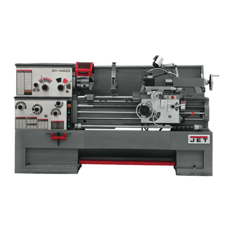
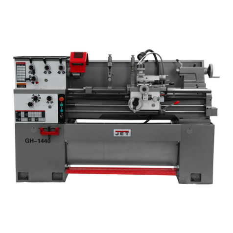
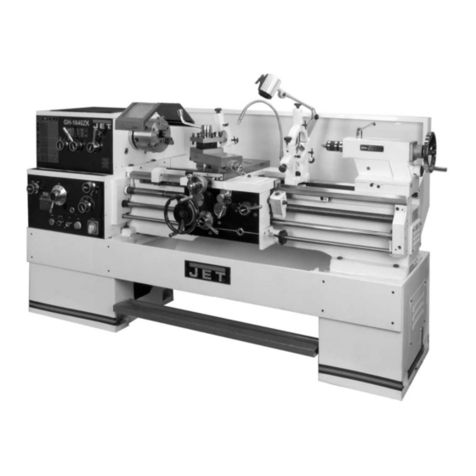
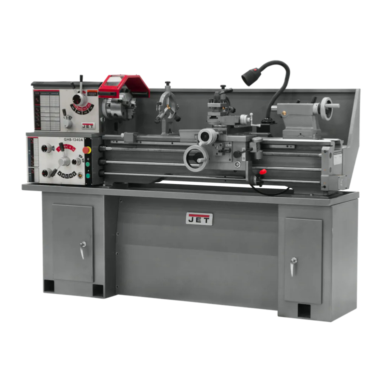
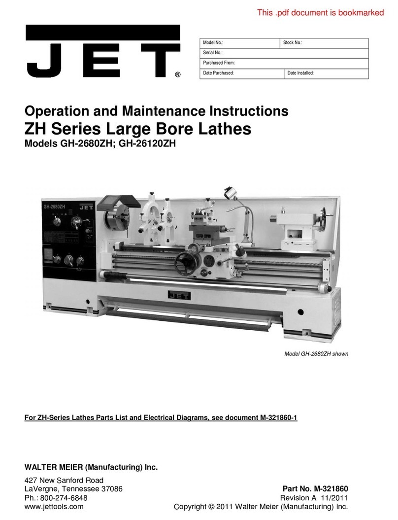
Jet GH-20 ZH Series User manual

GH-20xxZH-
GH
-
26xxZH
METAL LATHES
Original:
GB
Operating Instructions
Translations:
D
Gebrauchsanleitung
F
Mode d´emploi
Walter Meier (Fertigung) AG
Bahnstrasse 24
8603 Schwerzenbach
Switzerland
Phone +41 44 806 47 48
Fax +41 44 806 47 58
www.jettools.com
M - 5000766T-50000769T, 50000779T-50000832T 2009-12

CE-Conformity Declaration
Product: Metal Turning Lathe, (with DRO)
GH-2040ZH………. Stock Number: 50000766T, (50000830T)
GH-2060ZH………. Stock Number: 50000768T, (50000831T)
GH-2080ZH………. Stock Number: 50000769T, (50000832T)
GH-2640ZH……… Stock Number: 50000779T, (50000780T)
GH-2660ZH…….... Stock Number: 50000784T, (50000785T)
GH-2680ZH……… Stock Number: 50000789T, (50000790T)
GH-26120ZH…….. Stock Number: 50000794T, (50000795T)
Brand: JET
Manufacturer:
Walter Meier (Fertigung) AG, Bahnstrasse 24, 8603 Schwerzenbach, Switzerland
On our own responsibility we hereby declare that this product complies
with the regulations
* 2006/42/EC Machinery Directive
* 2004/108/EC EMC Directive (Electro Magnetic Compatibility)
* 2006/95/EC Low Voltage Directive
* 2002/95/EC RoHS Directive (Reduction of Hazardous Substances)
designed with consideration of the standards
** EN 12840, EN 60204-1, EN 50370-1, EN 50370-2
Technical file compiled by: Marcel Hofstetter, Head of Product Management
2009-12-30 Carl Müller, General Manager
Walter Meier (Fertigung) AG, Bahnstrasse 24, 8603 Schwerzenbach, Switzerland
2

2
GB - ENGLISH
Operating Instructions
Dear Customer,
Many thanks for the confidence you have shown in us with the purchase of your new JET-machine. This manual has been
prepared for the owner and operators of a JET GH-2040/ 2060/ 2080/ 2640/ 2660/ 2680/ 26120 ZH metal lathe to promote
safety during installation, operation and maintenance procedures. Please read and understand the information contained in
these operating instructions and the accompanying documents. To obtain maximum life and efficiency from your machine,
and to use the machine safely, read this manual thoroughly and follow instructions carefully.
…Table of Contents
1. Declaration of conformity
2. Warranty
3. Safety
4. Machine specifications
5. Transport and start up
6. Machine operation
7. Setup and adjustments
8. Main machine component description
9. Maintenance and inspection
10. Trouble shooting
11. Environmental protection
12. Available accessories
1. Declaration of conformity
On our own responsibility we hereby declare that
this product complies with the regulations* listed on
page 2. Designed in consideration with the
standards**.
2. Warranty
The Seller guarantees that the supplied product is free
from material defects and manufacturing faults. This
warranty does not cover anydefects which are caused,
either directly or indirectly, by incorrect use, carelessness,
accidental damage, repair, inadequate maintenance or
cleaning and normal wear and tear.
Guarantee and/or warranty claims must be made
within twelve months from the date of purchase (date
of invoice).Any further claims shall be excluded.
This warranty includes all guarantee obligations of
the Seller and replaces all previous declarations and
agreements concerning warranties.
The warranty period is valid for eight hours of daily
use. If this is exceeded, the warranty period shall be
reduced in proportion to the excess use, but to no
less than three months.
Returning rejected goods requires the prior express
consent of the Seller and is at the Buyer’s risk and
expense.
Further warranty details can be found in the General
Terms and Conditions (GTC). The GTC can be
viewed at www.jettools.com or can be sent by post
upon request.
The Seller reserves the right to make changes to the
product and accessories at any time.
3. Safety
3.1 Authorized use
This metal lathe is designed for turning and
drilling machinable metal and plastic materials
only. Machining of other materials is not
permitted and may be carried out in specific
cases only after consulting with the
manufacturer.
Never cut magnesium-
high danger to fire!
The workpiece must allow to safely be loaded and
clamped.

3
The proper use also includes compliance with the
operating and maintenance instructions given in this
manual.
The machine must be operated only by persons familiar
with its operation and maintenance and who are familiar
with its hazards.
The required minimum age must be observed.
The machine must only be used in a technically perfect
condition.
When working on the machine, all safety mechanisms
and covers must be mounted.
In addition to the safety requirements contained in these
operating instructions and your country’s applicable
regulations, you should observe the generally
recognized technical rules concerning the operation of
metalworking machines.
Any other use exceeds authorization.
In the event of unauthorized use of the machine, the
manufacturer renounces all liability and the responsibility
is transferred exclusively to the operator.
3.2 General safety notes
Metalworking machines can be dangerous if not used
properly. Therefore the appropriate general technical
rules as well as the following notes must be observed.
Read and understand the entire instruction manual
before attempting assembly or operation.
Keep this operating instruction close by the machine,
protected from dirt and humidity, and pass it over to the
new owner if you part with the tool.
No changes to the machine may be made.
Daily inspect the function and existence of the safety
appliances before you start the machine.
Do not attempt operation in this case, protect the
machine by unplugging the power cord.
Remove all loose clothing and confine long hair.
Before operating the machine, remove tie, rings,
watches, other jewellery, and roll up sleeves above
the elbows.
Wear safety shoes; never wear leisure shoes or
sandals.
Always assure a safe stands.
Always wear the approved working outfit.
Do not wear gloves.
Wear goggles when working
Install the machine so that there is sufficient space
for safe operation and work piece handling.
Keep work area well lighted.
The machine is designed to operate in closed rooms
and must be placed stable on firm and levelled
ground.
Make sure that the power cord does not impede work
and cause people to trip.
Keep the floor around the machine clean and free of
scrap material, oil and grease.
Stay alert! Give your work undivided attention. Use
common sense. Do not operate the machine when
you are tired.
Keep an ergonomic body position.
Maintain a balanced stance at all times.
Do not operate the machine under the influence of
drugs, alcohol or any medication. Be aware that
medication can change your behaviour.
Never reach into the machine while it is operating or
running down.
Never leave a running machine unattended. Before
you leave the workplace switch off the machine.
Keep children and visitors a safe distance from the
work area.
Do not operate the electric tool near inflammable
liquids or gases.
Observe the fire fighting and fire alert options, for
example the fire extinguisher operation and place.

4
Do not use the machine in a dump environment and do
not expose it to rain.
Work only with well sharpened tools.
Always close the chuck guard, tool post guard and pulley
cover before you start the machine.
Remove the chuck key and wrenches before machine
operation.
Specifications regarding the maximum or minimum size
of the work piece must be observed.
Do not remove chips and work piece parts until the
machine is at a standstill.
Do not stand on the machine.
Connection and repair work on the electrical installation
may be carried out by a qualified electrician only.
Have a damaged or worn power cord replaced
immediately.
Never place your fingers in a position where they could
contact any rotating parts or chips.
Check the save clamping of the work piece before
starting the machine.
Don’t exceed the clamping range of the chuck.
Work pieces longer than 3 times the chucking diameter
need to be supported by the tailstock or a steadyrest.
Avoid small chucking diameters at big turning diameters.
Avoid short chucking lengths.
Avoid small chucking contact.
Never exceed the max speed limitation of the work
holding device.
Choose a small spindle speed when working unbalanced
work pieces and for threading and tapping operations.
Any work piece stock extending the rear end of the
headstock must be covered on its entire length. High
danger of injury!
Long work pieces may need a steady rest support. A
long and thin work piece can suddenly bend at high
speed rotation.
Never move the tailstock or tailstock quill while the
machine is running.
Remove cutting chips with the aid of an appropriate
chip hook when the machine is at a standstill only.
Never stop the rotating chuck or work piece with your
hands.
Measurements and adjustments may be carried out
when the machine is at a standstill only.
Setup, maintenance and repair work may only be
carried out after the machine is protected against
accidental starting by pulling the mains plug.
3.3 Remaining hazards
When using the machine according to regulations
some remaining hazards may still exist.
The rotating work piece and chuck can cause injury.
Thrown and hot work pieces and cutting chips can
lead to injury.
Chips and noise can be health hazards. Be sure to
wear personal protection gear such as safety goggles
and ear protection.
The use of incorrect mains supplyor a damaged
power cord can lead to injuries caused by electricity.

5
4. Machine specifications
4.1 Technical data
GH-2040 / 2060 / 2080 ZH:
Swing over bed 500mm
Swing over bed gap 720mm
Length of bed gap 240mm
Swing over cross slide 310mm
Centre distance 1015/ 1530/ 2030mm
Width of bed 405mm
Spindle taper MT-7
Spindle nose DIN 55029 D1-8
(Camlock)
Hole through spindle ∅80 mm
Spindle speeds…24 9-1600 rpm
Tailstock ram travel 150mm
Tailstock taper MT5
Max tailstock cross displacement +/-15mm
Steady rest capacity 50 – 200mm
Follow rest capacity 20 – 100mm
Cross slide travel 310mm
Top slide travel 145mm
Tool size max 25 x 25 mm
Longitudinal feeds 65 0,063–2,52mm/r
Cross feeds 65 0,027–1,07mm/r
Metric threads...46 1–224mm/r
Inch threads…46 28 – 1/8 TPI
Modular Pitch 42 0,5 – 112MP
Diametral Pitch 45 56 – 1/4 DP
Lead screw pitch 12mm
Coolant tank capacity 15 L
Overall L x W x H
2500 / 3000 / 3500 x 1280 x 1410mm
Net weight 2750 / 3000 / 3250 kg
Main motor output power 7,5 kW (10 HP) S1
Reference current 18A
Extension cord (H07RN-F) 4x4mm²
Installation fuse protection 25A
GH-2640 / 2660 / 2680 / 26120 ZH:
Swing over bed 660mm
Swing over bed gap 870mm
Length of bed gap 240mm
Swing over cross slide 420mm
Max cutting dia for disc parts 520mm
Centre distance 1015/ 1530/ 2030 / 3050mm
Width of bed 405mm
Spindle taper Ø113m 1:20
Spindle nose DIN 55029 D1-8
(Camlock)
Hole through spindle ∅105 mm
Spindle speeds…12 36-1600 rpm
Tailstock ram travel 150mm
Tailstock taper MT5
Max tailstock cross displacement +/-15mm
Steady rest capacity 100 – 240mm
Follow rest capacity 20 – 100mm
Cross slide travel 310mm
Top slide travel 145mm
Tool size max 25 x 25 mm
Longitudinal feeds 65 0,063–2,52mm/r
Cross feeds 65 0,027–1,07mm/r
Metric threads...22 1–14mm/r
Inch threads…25 28 – 2 TPI
Modular Pitch 18 0,5 – 7MP
Diametral Pitch 24 56 – 4 DP
Lead screw pitch 12mm
Coolant tank capacity 15 L
Overall L x W x H
2500 / 3000 / 3500 / 4500 x 1100 x 1450mm
Net weight 2750 / 3145 / 3870 / 4250 kg
Main motor output power 7,5 kW (10 HP) S1
Reference current 18A
Extension cord (H07RN-F)4x4mm²
Installation fuse protection 25A

6
4.2 Noise emission
Acoustic pressure level (according to EN ISO 11202):
Idling at maximum speed LpA 82,4 dB(A)
The specified values are emission levels and are not
necessarily to be seen as safe operating levels.
As workplace conditions vary, this information is intended
to allow the user to make a better estimation of the
hazards and risks involved only.
4.3 Content of delivery
GH-2040 / 2060 / 2080 ZH:
6 Leveling pads
Splash guard
Tool post guard
Chuck guard with limit switch
250mm 3-jaw universal chuck with basic and reversing
jaws
320mm 4-jaw independent chuck
400mm faceplate
Four way tool post with indexing function
Steady rest
Follow rest
Foot brake with limit switch
Coolant system
Halogen work light
MT-5 life centre
MT-5 fixed centre
MT-7/ MT-5 reduction sleeve
Threading dial
Stop shaft with 5 adjustable cams (switch off of
longitudinal feed)
Operating tools in tool box
Oil can
Operating manual
Spare parts list.
GH-2640 / 2660 / 2680 / 26120 ZH:
6 Leveling pads
Splash guard
Tool post guard
Chuck guard with limit switch
325mm 3-jaw universal chuck with basic and
reversing jaws
400mm 4-jaw independent chuck
630mm faceplate
250mm drive plate
Four way tool post with indexing function
Steady rest
Follow rest
Foot brake with limit switch
Coolant system
Halogen work light
MT-5 life centre
MT-5 fixed centre
MT-5/ Ø113mm reduction sleeve
Threading dial
Stop shaft with 5 adjustable cams (switch off of
longitudinal feed)
Operating tools in tool box
Oil can
Operating manual
Spare parts list.

7
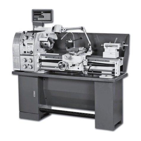
4.4 Machine description
Fig 1
1…Thread pitch lever
2…Speed change lever
3… Emergency Stop button
4…Push-button of cooling Pump
5…Main Motor Start button
6…Lamp Switch
7…Tool Post Clamp Lever
8…Coolant Delivery cock
9…Compound-rest knob
10…Quill Clamp Lever
11….Quill Clamp Lever
Fig 2
12…Tailstock quill Hand wheel
13…Spindle Forward / OFF / ReverseClutch Lever
14…Feeding and rapid speed Lever
15…Half Nut Lever
16…Main Motor Start /Stop Button
17…Cross feed Lever
18…Carriage Hand wheel
19…Power Switch
20….Feeding Speed Lever
21….Speed Change Lever
22…Feed Change Lever
23…Thread Selector Lever

8
Fig 3
N….Pulley cover
O.….Chuck guard
P….Tool post guard
Q…..Coolant nozzle
R……Halogen machine light
S…...3-axis digital readout (option)
5. Transport and start up
5.1 Transport and installation
The machine will be delivered in a closed crate.
For transport use a forklift or hand trolley. Make sure the
machine does not tip or fall off during transport.
The machine is designed to operate in closed rooms and
must have sufficient floor space to operate it and to have
access from all sides.
5.2 Assembly
If you notice transport damage while unpacking, notify
your supplier immediately. Do not operate the machine!
Dispose of the packing in an environmentally friendly
manner.
Clean all rust protected surfaces with petroleum, diesel
oil or a mild solvent.
Unbolt the lathe from the shipping crate bottom.
Move the tailstock to the tailstock end of the bed
Place 2 steel rods of sufficient strength into 2 holes of
lathe base.
Sling the lathe with properly rated straps ( Fig 4)
Fig 4
Move the saddle and tailstock to the tailstock end of
the bed and lock in place.
Caution:
The machine is heavy!
GH 2040 ZH 2750 kg
GH 2060 ZH 3000 kg
GH 2080 ZH 3250 kg
GH 2640 ZH 2750 kg
GH 2660 ZH 3145 kg
GH 2680 ZH 3870 kg
GH 26120 ZH 4250 kg
Use great care.
Assure the sufficient load capacity and proper
condition of your lifting devices.
Never step underneath suspended loads.

9
Fig 5
To lift the machine by forklift (Fig 5), the 2 foot pedal
upper stroke limit screws (A) must be removed, so that
the foot pedal can swing up freely and give space for the
forks.
Attention:
The machine is left weighted. The center of weight is
near the headstock.
Foundation:
The machine should be mounted on a solid foundation.
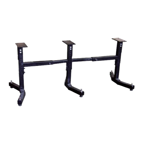
GH-2040-2640 / 2060-2660 / 2080_2680 / 26120 ZH
Size 1000 1500 2000 3000
l 1560 2060 2560 3560
L 2495 2995 3495 4495
Levelling:
Use a machinist’s precision level on the bed ways
and check to make sure that the lathe bed is level.
The lathe bed must be level to be accurate.
a) Deviation over bed length max 0,02/1000mm
b) Deviation over bed length max 0,04/1000mm
5.3 Mains connection
Mains connection and any extension cords used
must comply with applicable regulations.
The mains voltage must comply with the information
on the machine licence plate.
The mains connection must have a
25 A surge-proof fuse.
Only use power cords marked H07RN-F
Connections and repairs to the electrical equipment
may only be carried out by qualified electricians.
Connection takes place on the terminal box on the
back of the machine.
5.4 Initial lubrication
The lathe must be serviced at all lubrication points
and all reservoirs filled to operating level before the
lathe is placed into service!
Failure to comply may cause serious damage to the
lathe!
(see chapter 8 for lubrication).
After one month of operation the oil must be
changed on headstock, gearbox and apron.
The coolant tank has to be filled with coolant (see
chapter 8.7)

10
5.5 Starting operation
Before starting the machine check the proper
chucking (see chapter 6.2).
Before starting the machine be sure that the Forward
/OFF / Reverse clutch lever (13, Fig 2) is in neutral
position.
All lever positions must be changed only after the
machine has been stopped.
Turn ON the main power switch (located on the electric
box at the rear of the machine).
You can now start the motor with the main motor
Start/Stop button (16, Fig 2)
Check that the motor is running in the correct direction.
You can now start the spindle rotation with the Forward/
OFF / Reverse clutch lever (13, Fig 2)
Push the Clutch lever
- right and down for forward rotation
-right and up for backward rotation.
Return the lever to its 0-position to stop the spindle
rotation.
The foot break will stop the motor and break down the
spindle rotation.
Attention:
Lathe still has electric power.
The emergency stop button (3, Fig 1) stops all machine
functions.
Turn emergency stop button clockwise to reset.
Note:
The pulley cover (N, Fig 3) and the chuck guard (O) are
limit switch protected. They must be closed to operate
the machine.
5.6 Break in procedure:
To allow time for the gears and bearings to break-in and
run smoothly, do not run the lathe above 560 rpm for the
first 6 hours.
Headstock Clutch:
The headstock clutch is due to wear. To ensure normal
working of the spindle, the clutch must be suitably
adjusted.
- If the clutch is too loose, it outputs low power and is
easy to slip and get hot under load.
- If it is too tight, it becomes difficult to operate and
clutch mechanism will not engage properly.
Also it will loose the overload protect function.
See chapter 8 for clutch adjustment.
Warning:
Do not operate the machine when you notice power
failure due to clutch slipping.
6 Machine Operation
Warning:
Setup work may only be carried out after the
machine is protected against accidental starting.
With pressed emergency stop button.
Levers may be changed only when the machine
has been stopped.
Before starting the machine be sure that the
clutch lever (13, Fig 2) is in neutral position.
When the spindle runs, never turn any handle or
lever. Spindle speeds can be changed onlywhen the
main motor stops. Feed rate can be changed only
when the spindle runs at a low speed or stops.
Before starting the spindle, check if each handle or
lever is at a correct position to ensure normal
engagement of driving gears.
When operating forward/Off/ reverse clutch lever (13,
Fig2), be sure to turn it to the right position. Never
use “pre-position” for cutting at a reduced speed.
Lead screw is used only for threading instead of
longitudinal feeding so that its accuracy can be
maintained and service life prolonged.
In threading, the lead screw drives the apron directly
and the safety clutch of the apron has lost its
protection function. To avoid the machine parts being
damaged, be sure to select suitable cutting depth.
When loading or unloading the workpiece or getting
away from the machine, the operator must stop the
main motor.
6.1 Chucking
Chuck removal:
Before removing the chuck from the spindle, place
board across the bed ways under the chuck.
Support the chuck while turning three cam locks ¼
turn counter-clockwise.
Line up the two marks (A, Fig 6) for removal.

11
Fig 6
Carefully remove the chuck form the spindle.
Clean all contact surfaces.
Lift the chuck up to the spindle nose and press onto the
spindle.
Tighten in place byturning the cam locks ¼ turn
clockwise.
The index mark (A) on the camlock should be between
the two indicator arrows (B).
If not, adjust the cam studs by turning them in or out by
one turn as needed.
Tighten cam locks.
Attention:
Never exceed the max speed limitation of the work
holding device.
Jaw teeth and scroll must always be fully engaged.
Otherwise chuck jaws may break and fly off in rotation
(Fig 7).
Fig 7
Avoid long workpiece extensions. Parts may bend
(Fig 8) or fly off (Fig 9).
Use tailstock or rests to support.
Fig 8
Fig 9
Avoid short clamping contact (A, Fig 10) or clamping
on a minor part diameter (B).

12
Fig 10
Face locate the workpiece for added support.
6.2 Tool setup
The cutting angle is correct when the cutting edge is in
line with the centre axis of the work piece. Use the point
of the tailstock centre as a gauge and shims under the
tool to obtain the correct centre height.
Use a minimum of two clamping screws when installing
the cutting tool to the four way tool post.
Avoid big tool extensions.
6.3 Spindle speeds selection
The correct spindle speed depends on the type of
machining, the cutting diameter, the material to be
machined and the cutting tool.
These are recommended max. speeds for a 50mm
cutting diameter with carbide (HM) tools:
Aluminium, brass 1500 RPM
Cast iron 1000 RPM
Mild steel 800 RPM
High carbon steel 600 RPM
Stainless steel 300 RPM
If high speed steel (HSS) tools are used about 5 times
lower speeds must be chosen.
Generally speaking, the larger in relation the cutting
diameter, the smaller the possible RPM.
For example:
Turning mild steel at a diameter of 25mm allows a
speed of
1600 RPM max. with carbide tool
320 RPM max. with HSS tool
To change the spindle speed:
The speed may never be changed when the spindle
or motor are still running.
Move the speed select levers (2, Fig 1) according to
the speed you desire.
It may be necessary to turn the chuck byhand to help
the gears to engage.
6.4 Turning with auto feed
Several automatic longitudinal and cross feeds are
readily available by selection on the gearbox levers
(20, 22, 23, Fig 1).
Do not shift levers while the machine is running.
Move the feeding lever (14, Fig 2):
- left /right for longitudinal feed.
- up/down for cross feed
The correct feed depends on the material to be
cut, the cutting operation, the type of tool, the
rigidity of the work piece chucking, the depth of
cut and the desired surface quality.
For example:
Longitudinal OD-turning, mild steel of 25mm diameter
with a carbide tool at 1200 RPM and with rigid
chucking.
Stock removal and roughing cut:
Depth of cut 2mm
Feed per revolution 0,25mm
Finishing cut:
Depth of cut 0,5mm
Feed per revolution 0.1mm

13
Micro finishing and calibration cut:
Depth of cut 0,2mm
Feed per revolution 0.06mm
When roughing big diameters reduce the depth of cut!
6.5 Rapid traverse
Move the feeding lever (14, Fig 2):
- left /right for longitudinal feed.
- up/down for cross feed
Push the green rapid feed button on top of the lever to
speed up the movement.
Rapid longitudinal feed disengages the apron
handwheel.
Safety Note:
Rapid cross feed may only be used when the
Cross-handwheel is disengaged (pulled) and the handle
is layed flat.
6.6 Thread cutting
Threading is performed in multiple passes with a
threading tool.
Each depth of cut should be about 0,2mm and become
less for the finishing passes.
Set the thread pitch select levers (1, 20, 22, 23, Fig 1)
in proper position.
Note:
Coarse threads may only be cut at low spindle speeds.
A) To cut inch and metric threads
Set the machine up for the desired threading pitch and
first depth of cut.
Engage the halve nut (15, Fig 2).
The halve nut must be engaged during the entire
threading process.
- Start the machine at the lowest spindle speed.
- When the tool reaches the end of cut, stop the
motor and at the same time back the tool out of the
part so that it clears the thread (Attention inertia: Stop
the motor in time)
- Reverse the motor direction to allow the cutting tool
to travel back to the starting point.
Repeat these steps until you have obtained the
desired results.
B) To cut metric threads with threading dial:
On most metric threads the threading dial can be
used.
The halve nut can be opened at the end of cut, rather
than the motor being stopped and reversed.
The halve nut may only be engaged at the
corresponding graduation match on the threading
dial.
For thread pitches of 1 / 1,5 / 2 / 3 / 4 / 6 / 12 mm, the
halve nut can be engaged anytime.
(lead screw pitch =12mm =dividable by thread pitch).

14
6.7 Drilling operation
Use a drill chuck with MT-5 arbour (option) to hold
centring drills and twisted drills in the tailstock.
For recommended speeds refer to section 6.4
To eject the drill chuck, fully retract the tailstock quill.
7. Setup and adjustments
Warning:
Setup and adjustment work may only be carried out
after the machine is protected against accidental
starting.
Turn off the main switch and press the emergency
stop button!
7.1 Turning between centres
Mount the workpiece fitted with the drive dog between
centres.
The driver is driven by the drive plate (Fig 11).
Fig 11
7.2 Taper turning with tailstock
Turning up to a side angle of 5° can be achieved by
off-setting the tailstock.
To offset the tailstock (max +/-15mm possible),
Loosen the locking handle, loosen the front adjusting
screw and take up the same amounton the rear
adjusting screw.
Tighten the adjusting screws and the locking nut to
hold the tailstock in position.
The workpiece must be held between centres and
driven by the face plate and drive dog.
After taper turning, the tailstock must be returned to
its original position.
Turn a test piece and adjust until the machine turns a
perfect cylinder.
7.3 Taper turning with top slide
By angling the top slide, tapers may be turned.
Loosen two nuts and rotate the top slide according to
the graduated scale.
7.4 Three jaw universal chuck
With this universal chuck, cylindrical, triangular and
hexagonal stock may be clamped (Fig 12).
Fig 12
To hold big diameter stock, reverse the top jaws.
Use Molykote Paste G (or adequate grease) to
lubricate the jaws.

15
7.5 Four jaw independent chuck
This chuck has four independently adjustable chuck
jaws. These permit the holding of square and
asymmetrical pieces and enable the accurate concentric
set-up of cylindrical pieces.
7.6 Live centre
The live centre is mounted in ball bearings.
Its use is highly recommended for speeds above200
RPM.
To eject the live centre, fully retract the tailstock quill.
7.7 Steady and follow rest
The steady rest
serves as a support for longer shafts and ensures a safe
and chatter free operation.
The steady rest is mounted on the bed way with a
locking plate.
Tighten the fingers so that they are snug but not tight
against work piece.
Lubricate the fingers to prevent premature wear.
The follow rest
is mounted on the saddle and follows the movement of
the tool. It prevents flexing of long and thin work pieces
under pressure from the tool.
Set the fingers snug but not overly tight. Lubricate the
fingers to prevent premature wear.
7.8 Bed gap removal
Pull the taper pins (A, Fig 13) by tightening the hex nuts.
Remove the screws (B).
Bed gap can now be removed.
Fig 13
Before you install the bed gap, clean the contacting
surfaces thoroughly.
Remove nuts form the taper pins.
Slide taper pins into the holes and seat using a
mallet.
Tighten the screws.
7.9 Thread Pitch and Feed Selection
To obtain different thread pitches and different feed
settings, four handles 1, 23, 22 and 20 must be used
together.
Handle 1 is used to select the hand of thread leads.
Because of the overrunning clutch in the apron, the
tool post does not feed unless the thread being cut is
a right hand one.
Right hand thread, feed
Left hand thread, no feed
Handle 23 is used for the thread type selection. But it
is also used for altering the feed speed.
t------ for Metric threads
n------ for Inch threads
m------ for Module threads
DP ------ for Diametric pitches
“-•-”------ Driving the lead screw directly, not
through any thread change device.
Handle 22 is used for selecting the pitch and feed.
Handle 20 doubles the pitch and feed

16
I, II, III, IV: Lead screw works to cut threads.
A, B, C, D: Feed Rod works to do feeding.
Ratios between them:
I: II: III: IV = A:B:C:D = 1:2:4:8
When a thread excluded from thread chart is to be cut,
you need to move
handle 23 to “-•-”position
handle 20 to “IV” position
then reset the change gears.
Cautions about the machine operation:
Before starting the machine, check the lubrication of all
moving parts.
Be sure that the starting lever is at neutral position.
Turn on the power and the indicator will light.
Then the machine can be started.
Be familiar enough with the machine driving system, the
function and changing
Sequence of all operation levers or handles before
starting the machine.
Check accuracy of lever position. Be sure that levers are
at a fixed position.
All lever positions must be changed only after the
machine has been stopped.
8. Main Machine Component Description
Motor and V-Belt Drive:
The main motor is inside the front stand and coolant
system inside the rear stand.
The belts V-belts should be suitably adjusted by the
adjusting nuts (See Fig 14).
Fig 14
Clutch Type Headstock:
Through a multi-disc friction clutch and different gears,
the power is further transmitted to the spindle.
The spindle’s forward or reverse motion is controlled by
the clutch.
The clutch allows the manual control of spindle
starting and spindle reversing.
The clutch also is an overload protection.
Clutch Adjustment:
To ensure normal working of the spindle, the clutch
must be suitably adjusted.
- If the clutch is set too loose, it outputs less power
and is easy to slip and get hot.
- If it is set too tight, it becomes difficult to operate the
forward/STOP/reverse handle and the clutch will not
engage properly.
For forward and reverse rotation the clutch can be
adjusted independently.
- Protect the machine against accidental starting.
( Lock the main switch in Off-position).
- Remove the headstock cover (is made of plastic,
one person can lift it by hand).
- Determine the appropriate clutch
- Use a screwdriver and push in the index pin (B, Fig
15 and Fig 16) …it is spring loaded.
- Rotate the clutch nut (A) to the next index.
Fig 15
Note:
The clutch reacts quickly, adjust clutch nut (A) by one
division only.
You must feel and hear the clutch
engagement....clicking noise!
If clutch is adjusted too tight, it will not engage.
If the spindle does not stop in the OFF-position, the
forward/reverse clutch adjustment is out of balance.
(The spindle follows the direction with the tighter
clutch adjustment).

17
Fig 16
-Install the headstock cover.
-Test the clutch function (readjust if necessary).
Break:
After the clutch is disengaged, the main drive can be
stopped by the brake.
If the spindle can not be stopped in a short period, the
braking strap should be adjusted (See Fig 17).
Fig 17
Main Spindle and Bearings:
If the spindle precision can not meet the requirement,
first loosen nut 1
Loosen locking clip and loosen nut 2.
Adjust the play of the front and middle bearings through
nuts 3 and 4. After the adjustment tighten the loosened
nuts.
Fig 18
After the adjustment make an idle running at the
highest speed for two hours. The temperature must
remain below 70°C.
Feedbox:
The design allows to cut most threads without the
need for change gears.
Lead Screw:
The axial play of the lead screw can be eliminated by
adjusting the nuts (1, Fig 19)
Fig 19
Apron:
Power feed drive route is from feed rod to apron,
through safety clutch to worm, through gear drives to
longitudinal or cross movement.
To realize rapid feed at any time, an overstep clutch
is equipped on the worm axle.
When the rapid feed motor drives the worm axle, it
oversteps the feed rod in one direction.
When the rapid feed is stopped, the normal feed is
automatically engaged again.

18
Feed Overload Clutch:
To adjust the feed overload clutch, remove the cover (1,
Fig 20) and adjust screw (2).
Be sure not to set it too tight, otherwise no protection
function and the machine may be damaged.
Fig 20
4-Way Toolpost
During tool change, the tool rest is slightly raised.
During tool change, if the tool rest cannot reach the
desired position, loosen the screw (2, Fig 21) for spring
and steel ball.
If it over travels, tighten the screw.
To disassemble the toolpost, remove screw 1 and 2, take
out spring 3 and steel ball 4, then the lever and the tool
rest can be removed.
Fig 21
Cross slide:
The axial play of the cross slide spindle can be
eliminated.
Loosen set screw 1, then tighten screw 2 until the
clearance is eliminated. Finally tighten set screw 1
again.When the adjustment is finished, put on the
dust cover 3 (See Fig 22).
Fig 22
The dovetail guide ways on cross and top slide are
adjustable by tapered gibs.

19
Tailstock
Cross displacement of the tailstock can be realized.
Loosen set screw (2, Fig 23)
Adjust displacement with screws (1, Fig 24)
Fig 23
Fig 24
Change gear bracket
For most threads the standard setting can be used
(Fig 25, 26)
Fig 25
Fig 26
This manual suits for next models
22
Table of contents
Languages:
Other Jet Lathe manuals