Jet BD-920W Service manual

Operating Instructions and Parts Manual
9 x 20-inch Belt Drive Bench Lathe
Model BD-920W
WALTER MEIER (Manufacturing) Inc.
427 New Sanford Road
LaVergne, Tennessee 37086 Part No. M-321376
Ph.: 800-274-6848 Revision H 01/2013
www.waltermeier.com Copyright © 2013 Walter Meier (Manufacturing) Inc.

2
Warranty and Service
Walter Meier (Manufacturing) Inc., warrants every product it sells. If one of our tools needs service or repair, one of
our Authorized Service Centers located throughout the United States can give you quick service. In most cases, any
of these Walter Meier Authorized Service Centers can authorize warranty repair, assist you in obtaining parts, or
perform routine maintenance and major repair on your JET
®
tools. For the name of an Authorized Service Center in
your area call 1-800-274-6848.
MORE INFORMATION
Walter Meier is consistently adding new products to the line. For complete, up-to-date product information, check with
your local Walter Meier distributor, or visit www.jettools.com.
WARRANTY
JET products carry a limited warranty which varies in duration based upon the product (MW = Metalworking, WW =
Woodworking).
WHAT IS COVERED?
This warranty covers any defects in workmanship or materials subject to the exceptions stated below. Cutting tools,
abrasives and other consumables are excluded from warranty coverage.
WHO IS COVERED?
This warranty covers only the initial purchaser of the product.
WHAT IS THE PERIOD OF COVERAGE?
The general JET warranty lasts for the time period specified in the product literature of each product.
WHAT IS NOT COVERED?
Five Year Warranties do not cover woodworking (WW) products used for commercial, industrial or educational
purposes. Woodworking products with Five Year Warranties that are used for commercial, industrial or education
purposes revert to a One Year Warranty. This warranty does not cover defects due directly or indirectly to misuse,
abuse, negligence or accidents, normal wear-and-tear, improper repair or alterations, or lack of maintenance.
HOW TO GET SERVICE
The product or part must be returned for examination, postage prepaid, to a location designated by us. For the name
of the location nearest you, please call 1-800-274-6848.
You must provide proof of initial purchase date and an explanation of the complaint must accompany the
merchandise. If our inspection discloses a defect, we will repair or replace the product, or refund the purchase price,
at our option. We will return the repaired product or replacement at our expense unless it is determined by us that
there is no defect, or that the defect resulted from causes not within the scope of our warranty in which case we will,
at your direction, dispose of or return the product. In the event you choose to have the product returned, you will be
responsible for the shipping and handling costs of the return.
HOW STATE LAW APPLIES
This warranty gives you specific legal rights; you may also have other rights which vary from state to state.
LIMITATIONS ON THIS WARRANTY
WALTER MEIER LIMITS ALL IMPLIED WARRANTIES TO THE PERIOD OF THE LIMITED WARRANTY FOR
EACH PRODUCT. EXCEPT AS STATED HEREIN, ANY IMPLIED WARRANTIES OR MERCHANTABILITY AND
FITNESS ARE EXCLUDED. SOME STATES DO NOT ALLOW LIMITATIONS ON HOW LONG THE IMPLIED
WARRANTY LASTS, SO THE ABOVE LIMITATION MAY NOT APPLY TO YOU.
WALTER MEIER SHALL IN NO EVENT BE LIABLE FOR DEATH, INJURIES TO PERSONS OR PROPERTY, OR
FOR INCIDENTAL, CONTINGENT, SPECIAL, OR CONSEQUENTIAL DAMAGES ARISING FROM THE USE OF
OUR PRODUCTS. SOME STATES DO NOT ALLOW THE EXCLUSION OR LIMITATION OF INCIDENTAL OR
CONSEQUENTIAL DAMAGES, SO THE ABOVE LIMITATION OR EXCLUSION MAY NOT APPLY TO YOU.
Walter Meier sells through distributors only. The specifications in Walter Meier catalogs are given as general
information and are not binding. Members of Walter Meier reserve the right to effect at any time, without prior notice,
those alterations to parts, fittings, and accessory equipment which they may deem necessary for any reason
whatsoever. JET
®
branded products are not sold in Canada by Walter Meier.

3
Table of Contents
Warranty and Service............................................................................................................................................2
Table of Contents..................................................................................................................................................3
Introduction ...........................................................................................................................................................7
Specifications........................................................................................................................................................7
Unpacking .............................................................................................................................................................8
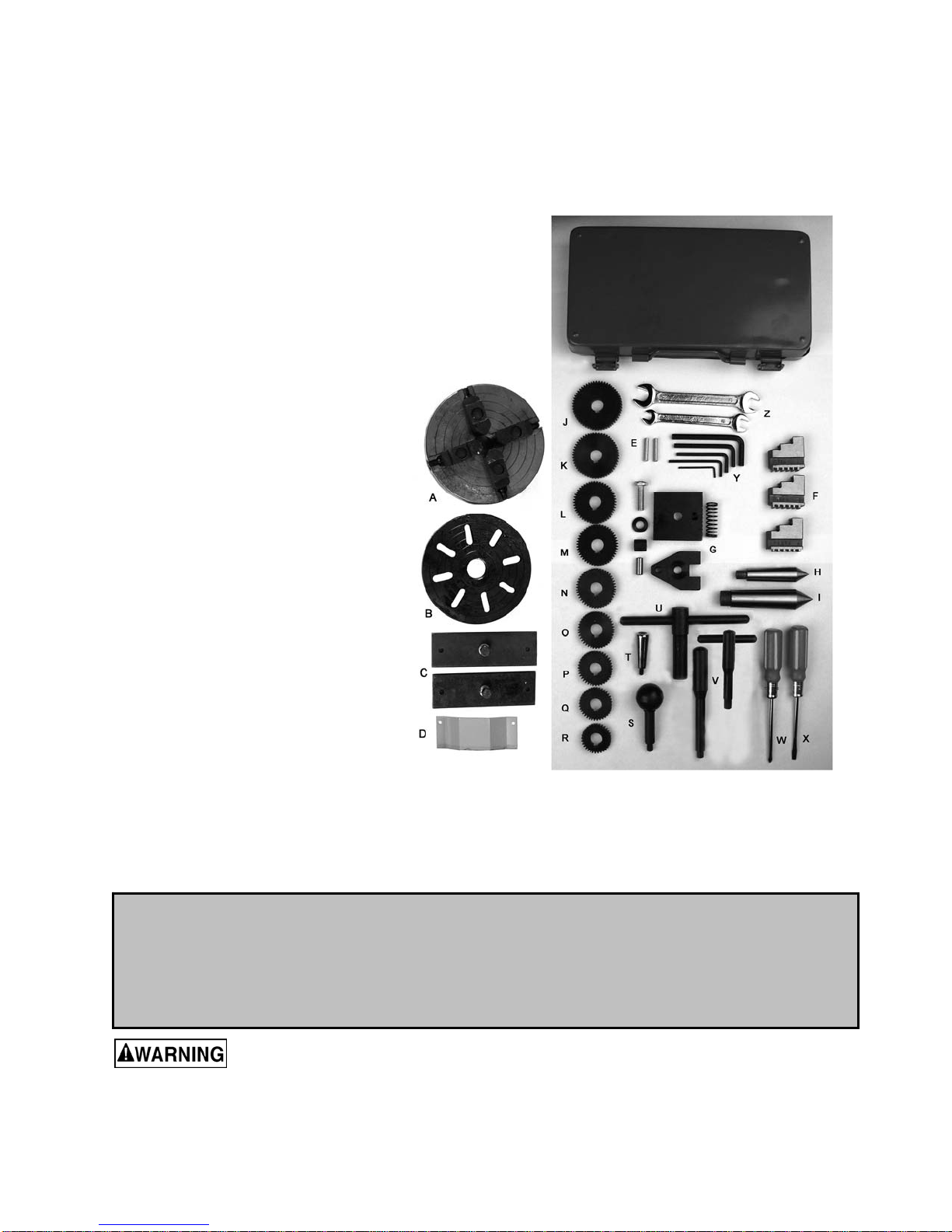
Contents of the Shipping Container......................................................................................................8
Set Up and Preparation for Operation...................................................................................................................9
General Description ..............................................................................................................................................9
Controls...............................................................................................................................................................12
Operation ............................................................................................................................................................13
Tool Set-Up........................................................................................................................................13
Manual Turning..................................................................................................................................13
Longitudinal Turning with Auto-Feed..................................................................................................13
Taper Turning Using Tailstock Off-Set................................................................................................14
Taper Turning by Setting the Top Slide ..............................................................................................14
Turning Between Centers...................................................................................................................14
Thread Cutting...................................................................................................................................15
Metric Thread Cutting.........................................................................................................................15
Lathe Accessories...............................................................................................................................................16
Adjustment and Replacement
...............................................................................................................................18
Adjustment of Main Spindle Bearings.................................................................................................18
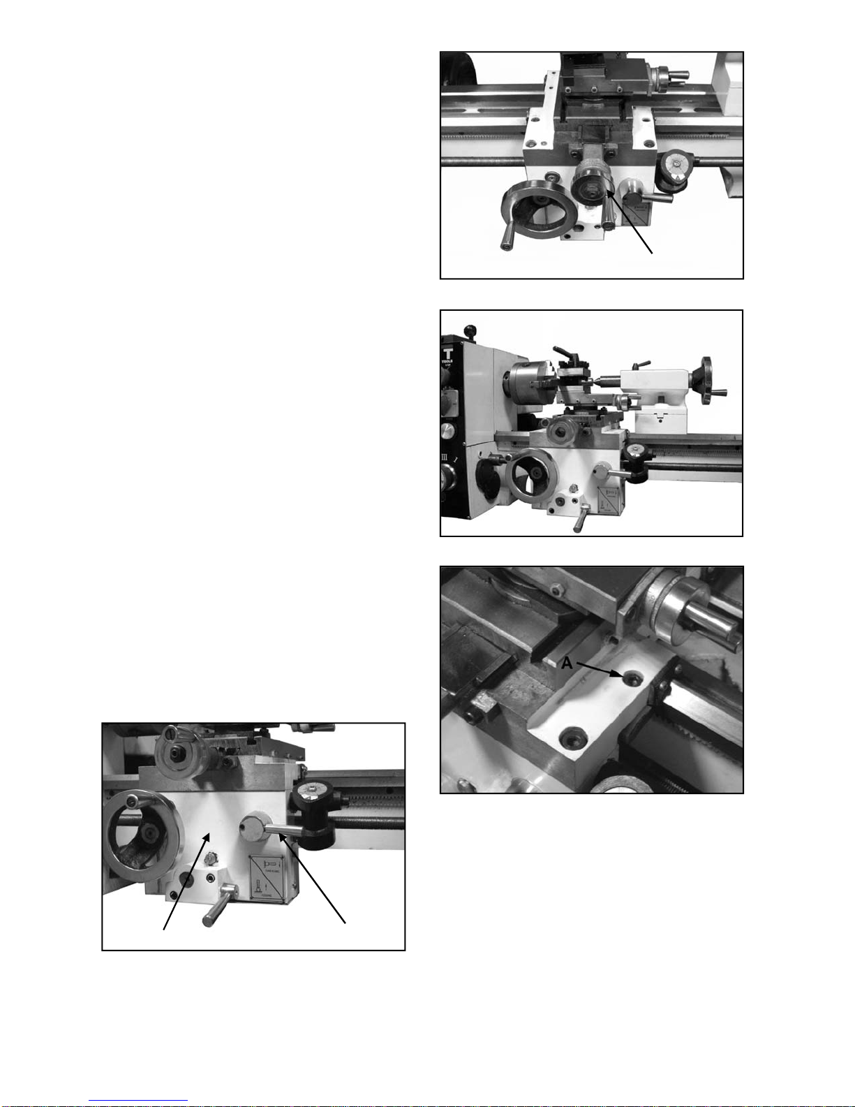
Adjustment of Cross and Top Slide ....................................................................................................18
Adjustment of Compound Feed Screw and Float................................................................................19
Cross Slide Screw..............................................................................................................................19
Compound Slide Spindle Backlash Adjustment ..................................................................................19
Adjustment of Half-Nut guide..............................................................................................................20
Replacing the Shear Pin in the Leadscrew .........................................................................................20
Replacing the V-Belt ..........................................................................................................................20
Lubrication Schedule...........................................................................................................................................21
Replacement Parts..............................................................................................................................................22
Headstock Assembly – Exploded View...............................................................................................22
Headstock Assembly – Parts List.......................................................................................................23
Drive Assembly – Exploded View.......................................................................................................24
Drive Assembly – Parts List................................................................................................................25
Tension Roller Assembly – Exploded View & Parts List......................................................................26
Quadrant Assembly – Exploded View & Parts List..............................................................................27
Electrical Assembly – Exploded View.................................................................................................28
Electrical Assembly – Parts List..........................................................................................................29
Gear Box Assembly – Exploded View.................................................................................................30
Gear Box Assembly – Parts List.........................................................................................................31
Apron Assembly – Exploded View......................................................................................................32
Apron Assembly – Parts List ..............................................................................................................33
Apron Assembly (continued) – Exploded View...................................................................................34
Apron Assembly (continued) – Parts List............................................................................................35
Saddle and Cross Slide – Exploded View...........................................................................................36
Saddle and Cross Slide Assembly – Parts List ...................................................................................37
Top Slide Assembly – Exploded View................................................................................................38
Top Slide Assembly – Parts List.........................................................................................................39
Tailstock Assembly – Exploded View.................................................................................................40
Tailstock Assembly – Parts List..........................................................................................................41
Steady Rest Assembly – Exploded View & Parts List..........................................................................42
Travel Rest Assembly – Exploded View & Parts List...........................................................................43
Lathe Bed Assembly – Exploded View ..............................................................................................44
Lathe Bed Assembly – Parts List........................................................................................................45
Wiring Diagram ...................................................................................................................................................46

4
A. GROUNDING INSTRUCTIONS
1. All grounded, cord-connected tools:
In the event of a malfunction or breakdown, grounding provides a path of least resistance for electric current to
reduce the risk of electric shock. This tool is equipped with an electric cord having an equipment-grounding
conductor and a grounding plug. The plug must be plugged into a matching outlet that is properly installed and
grounded in accordance with all local codes and ordinances.
Do not modify the plug provided - if it will not fit the outlet, have the proper outlet installed by a qualified
electrician.
Improper connection of the equipment-grounding conductor can result in a risk of electric shock. The conductor
with insulation having an outer surface that is green with or without yellow stripes is the equipment-grounding
conductor. If repair or replacement of the electric cord or plug is necessary, do not connect the equipment-
grounding conductor to a live terminal.
Check with a qualified electrician or service personnel if the grounding instructions are not completely
understood, or if in doubt as to whether the tool is properly grounded.
Use only 3-wire extension cords that have 3-prong grounding plugs and 3-pole receptacles that accept the
tool's plug.
Repair or replace damaged or worn cord immediately.
2. Grounded, cord-connected tools intended for use on a supply circuit having a nominal rating less
than 150 volts:
This tool is intended for use on a circuit that has an outlet that looks like the one illustrated in Sketch A. The
tool has a grounding plug that looks like the plug illustrated in Sketch A. A temporary adapter, which looks like
the adapter illustrated in Sketches B and C, may be used to connect this plug to a 2-pole receptacle as shown
in Sketch B if a properly grounded outlet is not available. The temporary adapter should be used only until a
properly grounded outlet can be installed by a qualified electrician.(This adapter is not permitted in Canada)
The green-colored rigid ear, lug, and the like, extending from the adapter must be connected to a permanent
ground such as a properly grounded outlet box.
3. Grounded, cord-connected tools intended for use on a supply circuit having a nominal rating
between 150 - 250 volts, inclusive:
This tool is intended for use on a circuit that has an outlet that looks like the one illustrated in Sketch D. The
tool has a grounding plug that looks like the plug illustrated in Sketch D. Make sure the tool is connected to an
outlet having the same configuration as the plug. No adapter is available or should be used with this tool. If the
tool must be reconnected for use on a different type of electric circuit, the reconnection should be made by
qualified service personnel; and after reconnection, the tool should comply with all local codes and ordinances.
4. Permanently connected tools:
This tool should be connected to a grounded metal permanent wiring system; or to a system having an
equipment-grounding conductor.

5
B. FOR ALL TOOLS AS APPLICABLE
1. READ AND UNDERSTAND the warnings posted on the machine and in this manual. Failure to comply with
all of these warnings may cause serious injury.
2. Replace the warning labels if they become obscured or removed.
3. This lathe is designed and intended for use by properly trained and experienced personnel only. If you are
not familiar with the proper and safe operation of a lathe, do not use until proper training and knowledge
have been obtained.
4. Do not use this lathe for other than its intended use. If used for other purposes, Walter Meier
(Manufacturing) Inc., disclaims any real or implied warranty and holds itself harmless from any injury that
may result from that use.
5. KEEP GUARDS IN PLACE and in working order.
6. REMOVE ADJUSTING KEYS AND WRENCHES. Form habit of checking to see that keys and adjusting
wrenches are removed from tool before turning it on.
7. KEEP WORK AREA CLEAN. Cluttered areas and benches invite accidents.
8. DON'T USE IN DANGEROUS ENVIRONMENT. Don't use power tools in damp or wet locations, or expose
them to rain. Keep work area well lighted.
9. KEEP CHILDREN AWAY. All visitors should be kept safe distance from work area.
10. MAKE WORKSHOP KID PROOF with padlocks, master switches, or by removing starter keys.
11. DON'T FORCE TOOL. It will do the job better and safer at the rate for which it was designed.
12. USE RIGHT TOOL. Don't force tool or attachment to do a job for which it was not designed.
13. WEAR PROPER APPAREL. Do not wear loose clothing, gloves, neckties, rings, bracelets, or other jewelry
which may get caught in moving parts. Nonslip footwear is recommended. Wear protective hair covering to
contain long hair.
14. ALWAYS USE SAFETY GLASSES. Also use face or dust mask if cutting operation is dusty. Everyday
eyeglasses only have impact resistant lenses, they are NOT safety glasses.
15. SECURE WORK. Use clamps or a vise to hold work when practical. It's safer than using your hand and it
frees both hands to operate tool.
16. DON'T OVERREACH. Keep proper footing and balance at all times.
17. MAINTAIN TOOLS WITH CARE. Keep tools sharp and clean for best and safest performance. Follow
instructions for lubricating and changing accessories.
18. Give your work undivided attention. Looking around, carrying on a conversation and “horse-play” are
careless acts that can result in serious injury.
19. DISCONNECT TOOLS before servicing; when changing accessories, such as blades, bits, cutters, and the
like.
20. REDUCE THE RISK OF UNINTENTIONAL STARTING. Make sure switch is in off position before plugging
in.
Other manuals for BD-920W
3
Table of contents
Other Jet Lathe manuals

Jet
Jet BD-920W User manual

Jet
Jet GHB-1236 Troubleshooting guide

Jet
Jet Elite E-1236VS Parts list manual

Jet
Jet JWL-1015 Datasheet

Jet
Jet GH-1640ZX User manual

Jet
Jet JML-1014VSI User manual

Jet
Jet E-1440VS Service manual

Jet
Jet JWL-1640EVS Service manual

Jet
Jet JML-1014 User manual

Jet
Jet JWL-1221VS Service manual