Jet JPJ-12B Service manual

Operating Instructions and Parts Manual
12-inch Planer/Jointer
Models JPJ-12B, JPJ-12BHH
JET
427 New Sanford Road
La Vergne, Tennessee 37086 Part No. M-715100
Ph.: 800-274-6848 Edition 1 10/2021
www.jettools.com Copyright © 2021 JET

2
1.0 Warranty and Service
JET warrants every product it sells against manufacturers’ defects. If one of our tools needs service or repair, please
contact Technical Service by calling 1-800-274-6846, 8AM to 5PM CST, Monday through Friday.
Warranty Period
The general warranty lasts for the time period specified in the literature included with your product or on the official JET
branded website.
JET products carry a limited warranty which varies in duration based upon the product. (See chart below)
Accessories carry a limited warranty of one year from the date of receipt.
Consumable items are defined as expendable parts or accessories expected to become inoperable within a
reasonable amount of use and are covered by a 90-day limited warranty against manufacturer’s defects.
Who is Covered
This warranty covers only the initial purchaser of the product from the date of delivery.
What is Covered
This warranty covers any defects in workmanship or materials subject to the limitations stated below. This warranty
does not cover failures due directly or indirectly to misuse, abuse, negligence or accidents, normal wear-and-tear,
improper repair, alterations, or lack of maintenance. JET woodworking machinery is designed to be used with Wood.
Use of these machines in the processing of metal, plastics, or other materials may void the warranty. The exceptions
are acrylics and other natural items that are made specifically for wood turning.
Warranty Limitations
Woodworking products with a Five-Year Warranty that are used for commercial or industrial purposes default to a Two-
Year Warranty. Please contact Technical Service at 1-800-274-6846 for further clarification.
How to Get Technical Support
Please contact Technical Service by calling 1-800-274-6846. Please note that you will be asked to provide proof
of initial purchase when calling. If a product requires further inspection, the Technical Service representative will
explain and assist with any additional action needed. JET has Authorized Service Centers located throughout the United
States. For the name of an Authorized Service Center in your area call 1-800-274-6846 or use the Service Center
Locator on the JET website.
More Information
JET is constantly adding new products. For complete, up-to-date product information, check with your local distributor
or visit the JET website.
How State Law Applies
This warranty gives you specific legal rights, subject to applicable state law.
Limitations on This Warranty
JET LIMITS ALL IMPLIED WARRANTIES TO THE PERIOD OF THE LIMITED WARRANTY FOR EACH PRODUCT.
EXCEPT AS STATED HEREIN, ANY IMPLIED WARRANTIES OF MERCHANTABILITY AND FITNESS FOR A
PARTICULAR PURPOSE ARE EXCLUDED. SOME STATES DO NOT ALLOW LIMITATIONS ON HOW LONG AN
IMPLIED WARRANTY LASTS, SO THE ABOVE LIMITATION MAY NOT APPLY TO YOU.
JET SHALL IN NO EVENT BE LIABLE FOR DEATH, INJURIES TO PERSONS OR PROPERTY, OR FOR
INCIDENTAL, CONTINGENT, SPECIAL, OR CONSEQUENTIAL DAMAGES ARISING FROM THE USE OF OUR
PRODUCTS. SOME STATES DO NOT ALLOW THE EXCLUSION OR LIMITATION OF INCIDENTAL OR
CONSEQUENTIAL DAMAGES, SO THE ABOVE LIMITATION OR EXCLUSION MAY NOT APPLY TO YOU.
JET sells through distributors only. The specifications listed in JET printed materials and on official JET website are
given as general information and are not binding. JET reserves the right to effect at any time, without prior notice, those
alterations to parts, fittings, and accessory equipment which they may deem necessary for any reason whatsoever.
JET®branded products are not sold in Canada by JPW Industries, Inc.
Product Listing with Warranty Period
90 Days –Parts; Consumable items
1 Year –Motors; Machine Accessories
2 Year –Metalworking Machinery; Electric Hoists, Electric Hoist Accessories; Woodworking Machinery used
for industrial or commercial purposes
5 Year –Woodworking Machinery
Limited Lifetime –JET Parallel clamps; VOLT Series Electric Hoists; Manual Hoists; Manual Hoist
Accessories; Shop Tools; Warehouse & Dock products; Hand Tools; Air Tools
Note: JET is a division of JPW Industries, Inc. References in this document to JET also apply to JPW Industries, Inc.,
or any of its successors in interest to the JET brand.

3
2.0 Table of Contents
Section Page
1.0 Warranty and Service.....................................................................................................................................2
2.0 Table of Contents...........................................................................................................................................3
3.0 Safety Warnings.............................................................................................................................................4
4.0 Specifications.................................................................................................................................................6
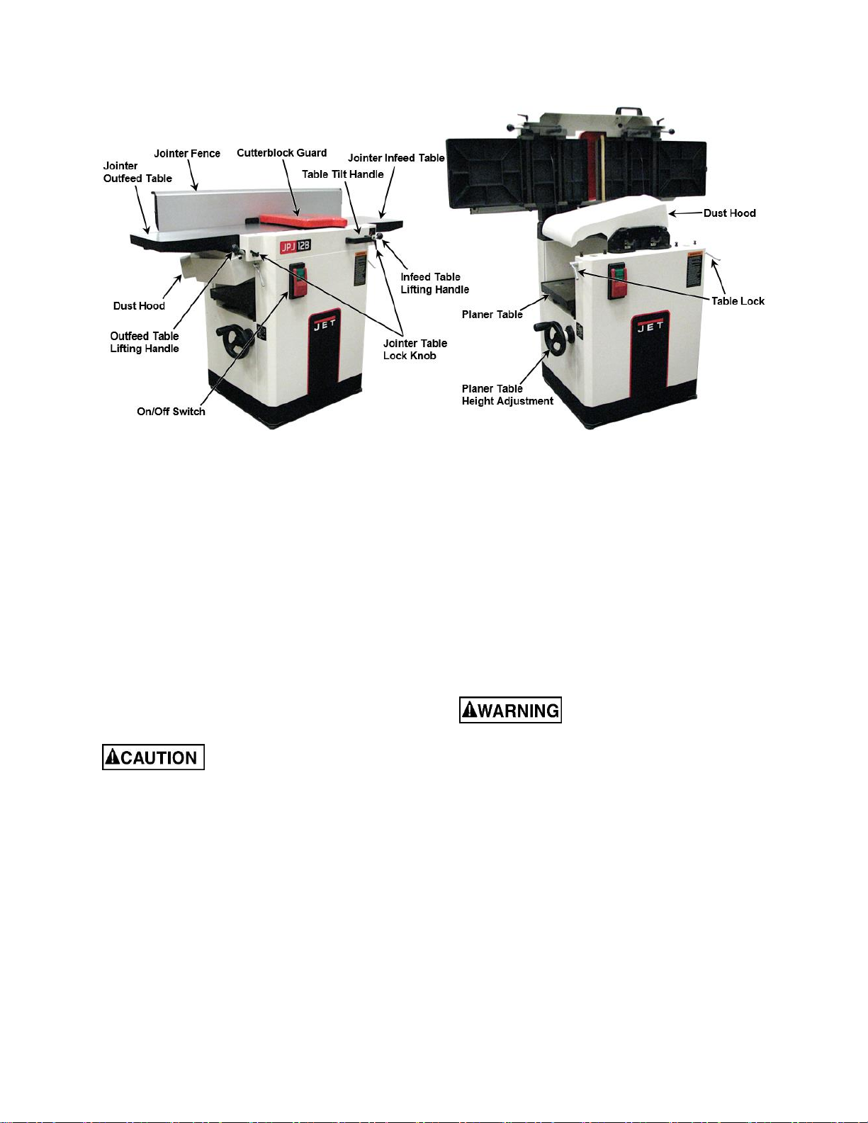
5.0 Features and Terminology .............................................................................................................................7
6.0 Receiving .......................................................................................................................................................7
7.0 Unpacking ......................................................................................................................................................7
9.1 Contents of Shipping Container .................................................................................................................7
8.0 Electrical Connection .....................................................................................................................................7
9.0 Operating Controls.........................................................................................................................................8
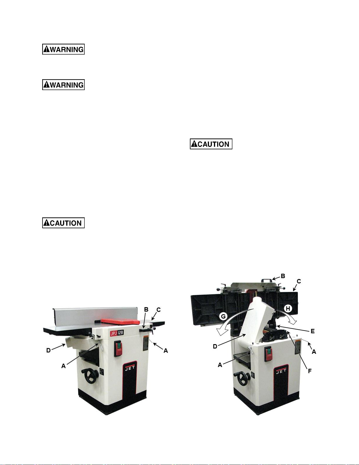
9.1 Jointer to Planer Setup...............................................................................................................................8
9.2 Planer to Jointer Setup...............................................................................................................................8
9.3 Control Switch............................................................................................................................................9
9.4 Planer Controls and Adjustments...............................................................................................................9
9.5 Jointer Controls and Adjustments ..............................................................................................................9
10.0 Adjustments ...............................................................................................................................................10
10.1 Fence Stop Adjustments ........................................................................................................................10
10.2 Table and Knife Adjustments .................................................................................................................11
10.3 Coplanar Alignment................................................................................................................................11
10.4 Setting Knives at Correct Height and Parallel to Outfeed Table ............................................................13
10.5 Replacing Cutterhead Knives (Straight Knives Only).............................................................................15
10.6 Replacing or Rotating Knife Inserts (Helical Cutterhead Only) ..............................................................16
10.7 Jointer Table Lock Handle Adjustment...................................................................................................16
10.8 Belt Replacement...................................................................................................................................17
10.9 Feed Roller Height Adjustment ..............................................................................................................18
10.10 Feed Roller Pressure Adjustment ........................................................................................................18
10.11 Planer Table Adjustment......................................................................................................................19
11.0 Basic Operations........................................................................................................................................20
11.1 Dust Collection .......................................................................................................................................20
11.2 Initial Startup ..........................................................................................................................................20
11.3 Changing Mode of Operation .................................................................................................................20
11.4 Jointer Operations..................................................................................................................................20
11.5 Planer Operations ..................................................................................................................................22
12.0 Maintenance...............................................................................................................................................23
12.1 Blade Care .............................................................................................................................................23
12.2 Sharpening the Knives (Straight Knives Only) .......................................................................................24
13.0 Lubrication..................................................................................................................................................24
14.0 Troubleshooting the JPJ-12B,JPJ-12BHH.................................................................................................25
14.1 Performance Troubleshooting –Jointer.................................................................................................25
14.2 Performance Troubleshooting –Planer..................................................................................................26
14.3 Mechanical Troubleshooting –Planer/Jointer........................................................................................27
15.0 Replacement Parts.....................................................................................................................................27
15.1 Infeed Table Assembly –Exploded View...............................................................................................28
15.2 Infeed Table Assembly –Parts List........................................................................................................29
15.3 Outfeed Table Assembly –Exploded View............................................................................................30
15.4 Outfeed Table Assembly –Parts List.....................................................................................................31
15.5 Cutterhead Assembly –Exploded View.................................................................................................32
15.6 Cutterhead Assembly –Parts List..........................................................................................................33
15.7 Planer Table Assembly –Exploded View...............................................................................................34
15.8 Planer Table Assembly –Parts List .......................................................................................................35
15.9 Blade Guard Assembly –Exploded View...............................................................................................36
15.10 Blade Guard Assembly –Parts List......................................................................................................37
15.11 Gearbox Assembly –Exploded View...................................................................................................38
15.12 Gearbox Assembly –Parts List............................................................................................................39
15.13 Cabinet Assembly –Exploded View.....................................................................................................40
15.14 Cabinet Assembly –Parts List .............................................................................................................41
15.15 Fence Assembly –Exploded View.......................................................................................................43
15.16 Fence Assembly –Parts List................................................................................................................44
16.0 Electrical Connections for JPJ-12B, JPJ-12BHH.......................................................................................45
17.0 Optional Accessories .................................................................................................................................46

4
3.0 Safety Warnings
1. Read and understand the entire owner's manual before attempting assembly or operation.
2. Read and understand the warnings posted on the machine and in this manual. Failure to comply with all of
these warnings may cause serious injury.
3. Replace the warning labels if they become obscured or removed.
4. This woodworking Planer-Jointer is designed and intended for use by properly trained and experienced
personnel only. If you are not familiar with the proper and safe operation of a woodworking jointer or planer,
do not use until proper training and knowledge have been obtained.
5. Do not use this machine for other than its intended use. If used for other purposes, JET disclaims any real
or implied warranty and holds itself harmless from any injury that may result from that use.
6. Always wear approved safety glasses/face shield while using this woodworking planer-jointer.
Note:Everyday eyeglasses only have impact resistant lenses; they are not safety glasses.
7. Before operating this woodworking planer-jointer, remove tie, rings, watches, and other jewelry, and roll
sleeves up past the elbows. Do not wear loose clothing. Confine long hair. Non-slip footwear or anti-skid
floor strips are recommended. Do not wear gloves.
8. Wear ear protectors (plugs or muffs) during extended periods of operation.
9. Do not operate this machine while tired or under the influence of drugs, alcohol, or any medication.
10. Make certain the switch is in the OFF position before connecting the machine to the power source.
11. Make certain the machine is properly grounded.
12. Make all machine adjustments or maintenance with the machine unplugged from the power source.
13. Remove adjusting keys and wrenches. Form a habit of checking to see that keys and adjusting wrenches
are removed from the machine before turning it on.
14. Keep safety guards in place at all times when the machine is in use. If removed for maintenance purposes,
use extreme caution and replace the guards immediately.
15. Make sure the planer-jointer is firmly secured to the floor or bench before use.
16. Check damaged parts. Before further use of the machine, a guard or other part that is damaged should be
carefully checked to determine that it will operate properly and perform its intended function. Check for
alignment of moving parts, binding of moving parts, breakage of parts, mounting and any other conditions
that may affect its operation. A guard or other part that is damaged should be properly repaired or replaced.
17. Provide for adequate space surrounding work area and non-glare, overhead lighting.
18. Keep the floor around the machine clean and free of scrap material, oil, and grease.
19. Keep visitors a safe distance from the work area. Keep children away.
20. Make your workshop child proof with padlocks, master switches or by removing starter keys.
21. Give your work undivided attention. Looking around, carrying on a conversation and “horse-play” are
careless acts that can result in serious injury.
22. Maintain a balanced stance at all times so that you do not fall or lean against the cutterhead or other moving
parts. Do not overreach or use excessive force to perform any machine operation.
23. Use the right tool at the correct speed and feed rate. Do not force a tool or attachment to do a job for which
it was not designed. The right tool will do the job better and more safely.
24. Use recommended accessories; improper accessories may be hazardous.
25. Maintain tools with care. Keep cutters sharp and clean for the best and safest performance. Follow
instructions for lubricating, and changing accessories.

5
26. Make sure the workpiece is securely attached or clamped to the table. Never use your hand to hold the
workpiece.
27. Turn off the machine before cleaning. Use a brush or compressed air to remove chips or debris —do not
use your hands.
28. Do not stand on the machine. Serious injury could occur if the machine tips over.
29. Never leave the machine running unattended. Turn the power off and do not leave the machine until the
cutterhead comes to a complete stop.
30. Before turning on machine, remove all extra equipment such as keys, wrenches, scrap, stock, and cleaning
rags away from the machine.
Jointer Operation
31. Always use a hold-down or push block when surfacing stock less than 12" long, 3" wide, or 3" thick.
32. Do not perform jointing operations on material shorter than 8", narrower than 3/4", or less than 1/4" thick.
33. Hands must never be closer than 3" to the cutterhead (see the Figure
at right).
34. Never apply pressure to stock directly over the cutterhead. This may
result in the stock tipping into the cutterhead along with the operator's
fingers. Position hands away from extreme ends of stock, and push
through with a smooth, even motion. Never back workpiece toward the
infeed table.
35. To avoid kickback, the grain must run in the same direction you are cutting. Before attempting to joint or
plane, each workpiece must be carefully examined for stock condition and grain orientation.
36. When working with a swirl grain wood or burls, making it necessary to plane against the grain, use a lesser
depth of cut and a slow rate of feed.
37. Move the hands in an alternate motion from back to front as the work continues through the cut. Never pass
the hands directly over the cutter knife. As one hand approaches the knives, remove it from the stock in an
arc motion and place it back on the stock in a position beyond the cutter knife.
38. At all times hold the stock firmly against the table and fence.
Planer Operation
39. Keep hands outside the machine. NEVER reach under the guards to try to clear stock that stops feeding. Do
not clear chips and sawdust with hands; use a brush. Do not have any part of the hands under that part of
the board that is over the table when starting a cut; the infeed roll will engage the board and force it down
against the table causing a pinching action.
40. Check stock condition. Do not plane boards with loose knots or with nails or any foreign material on its
surface. Knife impact on these objects can cause the knives to be pulled out and cause them to shatter
against the chipbreaker or pressure bar. Twisted, warped, or in wind stock should first be jointed on one
surface before attempting to plane a parallel surface on the planer. Serious stock flaws cannot be removed
by use of a planer alone.
41. To avoid kickbacks, use this machine for single board surfacing only. Never make cuts deeper than 5/32"
(4mm).
WARNING: This product can expose you to chemicals including lead which is known to the State of
California to cause cancer and birth defects or other reproductive harm. For more information go to
http://www.p65warnings.ca.gov.
WARNING: Drilling, sawing, sanding, or machining wood products generates wood dust and other
substances known to the State of California to cause cancer. Avoid inhaling dust generated from wood products
or use a dust mask or other safeguards for personal protection.
Wood products emit chemicals known to the State of California to cause birth defects or other reproductive
harm. For more information go to http://www.p65warnings.ca.gov/wood.

6
Familiarize yourself with the following safety notices used in this manual:
This means that if precautions are not heeded, it may result in minor injury and/or possible
machine damage.
This means that if precautions are not heeded, it may result in serious injury or possibly even
death.
4.0 Specifications
Model number ....................................................................... JPJ-12B................................................ JPJ-12BHH
Stock number..........................................................................715100.......................................................715155
Cutterhead speed (rpm)..............................................................5300...........................................................5300
Cutterhead diameter (in.) ............................................................2-3/4...........................................................2-3/4
Number of knives..............................................................................3.................................. 42 four-sided inserts
Knife size (LxWxT) (in.).....................................12-3/16 x 11/16 x 1/8...................................... 0.59 x 0.59 x 0.10
Dust port outside diameter (in.).........................................................4.................................................................4
Dust collection minimum (CFM)....................................................550.............................................................550
Jointer table size (LxW) (in.) ...........................................55 x 12-1/32...............................................55 x 12-1/32
Table height from floor (in.).......................................................33-1/2.........................................................33-1/2
Maximum stock removal (in.).........................................................1/8..............................................................1/8
Fence size (LxH) (in.)....................................................43-1/4 x 5-7/8.............................................43-1/4 x 5-7/8
Fence tilt.......................................................................... 90°to 45°R................................................90°to 45°R
Fence positive stop...................................................... 90°and 45°R.............................................90°and 45°R
Fence travel (in.) ...............................................................................6.................................................................6
Planer table size (LxW) (in.)............................................25 x 12-1/32...............................................25 x 12-1/32
Maximum workpiece thickness (in.) ............................................8-3/4...........................................................8-3/4
Maximum depth of cut (in.)...........................................................5/32............................................................5/32
Minimum length of workpiece (in.) ..................................................10...............................................................10
Feed rate (low speed / high speed) (fpm) ................................16 / 26........................................................16 / 26
Table movement per one handwheel revolution (in.)...................5/32............................................................5/32
Motor, TEFC...................................3HP, 1PH, 230V only, 60Hz, 15A.............. 3HP, 1PH, 230V only, 60Hz, 15A
Switch...............................................magnetic switch and limit switch................magnetic switch and limit switch
Power cord.............................................................14AWG 300V, 6 ft......................................14AWG 300V, 6 ft
Power cord plug ..............................................CSA 6-15P, 15A/250V............................... CSA 6-15P, 15A/250V
Overall dimensions (LxWxH) (in.) .................55-7/16 x 28-15/16 x 40.............................55-7/16 x 28-15/16 x 40
Stand footprint (LxW) (in.).................................................24 x 21-1/4.................................................24 x 21-1/4
Net weight (lb)...............................................................................453.............................................................453
The specifications in this manual are given as general information and are not binding. JET reserves the right to effect,
at any time and without prior notice, changes or alterations to parts, fittings, and accessory equipment deemed
necessary for any reason whatsoever.
Read and understand the entire contents of this manual before attempting
assembly or operation! Failure to comply may cause serious injury!

7
5.0 Features and Terminology
Figure 1
6.0 Receiving
Carefully unpack the machine and any loose
items from the wood case and inspect for
damage. Any damage should be reported
immediately to your distributor and shipping
agent. Before proceeding further, read your
manual thoroughly to familiarize yourself with
proper assembly, maintenance, and safety
procedures.
Remove the clear plastic protective sheets and
remove the protective coating from the tables and
cutterhead. This coating may be removed with a
soft cloth moistened with kerosene. Do not use
acetone, gasoline, or lacquer thinner for this
purpose. Do not use solvents on plastic parts.
Use care when cleaning the
cutterhead; the knives are very sharp.
7.0 Unpacking
1. Remove all contents from the shipping
carton. Do not discard the carton or packing
material until the machine is set up and
running satisfactorily.
2. Inspect the contents for shipping damage.
Report damage, if any, to your distributor.
This machine arrives fully assembled. However,
some tools may be needed for adjustments.
9.1 Contents of Shipping Container
1 Planer/Jointer
2 Push blocks
1 6mm hex wrench
1 Aluminum knife gauge (JPJ-12B only)
2 Star point screwdrivers (JPJ-12BHH only)
10 Knife inserts (JPJ-12BHH only)
10 Knife insert screws (JPJ-12BHH only)
1 Owner's manual
1 Warranty card
8.0 Electrical Connection
All electrical connections
must be done by a qualified electrician. All
adjustments or repairs must be done with the
machine disconnected from the power
source, unplugged. Failure to comply may
result in serious injury!
The model JPJ-12B and JPJ-12BHH Planer-
Jointer is rated at 230V. This machine is not
supplied with a plug. Use a plug and outlet rated
at least 30 amps. The circuit for the machine
should also be protected by at least a 30-amp
circuit breaker or fuse.
Make sure the cutterhead rotates in the proper
direction. If it does not, disconnect machine from
power supply and reverse two of the phase wires
on the supply input.

8
9.0 Operating Controls
Disconnect machine from
power source before making any
adjustments. Failure to comply may cause
serious injury.
Cutterhead knives are
dangerously sharp. Use extreme caution
when working around them. Failure to comply
may cause serious injury.
9.1 Jointer to Planer Setup
Refer to Figures 2 and 3:
To change the machine configuration from jointer
to planer:
1. Release both cabinet table locks (A) by
rotating the handles toward the operator,
then pulling away from the machine.
2. Raise the table (C) using the handle (B).
When raised, the table should be in the
vertical position as shown in C, Fig. 3. The
latch (E) should be engaged, preventing the
table from an accidental forward fall.
Table is heavy. Use care when
raising. Failure to comply may cause serious
injury.
3. Position the dust chute (D) to the right (H).
Use extreme care to avoid contact with
cutterhead knives.
Note: The planer table may need to be lowered
to allow clearance needed to position the dust
chute.
Figure 2
9.2 Planer to Jointer Setup
Refer to Figures 2 and 3:
To change the machine configuration from planer
to jointer:
1. Pull the dust chute release knob (F) and
reposition the dust chute (D) to the left (G). It
should be positioned as shown in D, Fig. 2.
Note: The planer table may need to be lowered
to allow clearance needed to position the dust
chute.
2. Release the latch (E) and bring the table
forward using the handle (B). It should be
positioned as shown in C, Fig. 2.
Table is heavy. Use care when
lowering. Failure to comply may cause
serious injury.
3. Lock the table (C) by pushing the lock
handles (A) in toward the machine and
rotating down (away from the operator).
Figure 3

9
9.3 Control Switch
Refer to Figure 4:
Press the green switch to start. Press the red
switch to stop.
To prevent unauthorized or accidental starting of
the machine, remove the safety key from the
green switch and store in a safe place. The key
must be reinserted to start the machine.
Figure 4
9.4 Planer Controls and Adjustments
Refer to Figure 5:
Table Height Adjustment
To set the planer table height, rotate the height
adjustment handwheel (E) counterclockwise to
raise the planer table (C), clockwise to lower.
Each revolution of the handwheel (E) results in a
5/32" up or down movement of the table (C). A
scale on the handwheel column indicates the
amount of handwheel rotation. A pointer (B)
indicates the table position relative to the
cutterhead on the scale (A) located on the side of
the cabinet.
Power Feed
The gearbox has two feed speeds. These are set
by pulling out or pushing in the shift lever (D).
Always change feed speed while the machine
is running. A diagram showing lever positions
and associated feed speeds can be found above
the gearbox cover. It is also shown in Figure 6.
Planer must be running when
changing the feed rate. Do not attempt to
change the feed speed while stock is passing
through the machine. Failure to comply may
damage the gearbox.
Figure 5
Figure 6
9.5 Jointer Controls and
Adjustments
Outfeed Table Height Adjustment
Refer to Figure 7:
The outfeed table lock handle (C) and outfeed
table adjustment handle (B) control the height
adjustment of the outfeed table (A).The outfeed
table is initially adjusted at the factory and should
not be repositioned except during certain
adjustments. These are described in sect. 10.2,
Table and Knife Adjustments.
Infeed Table Height Adjustment
Refer to Figure 7:
The infeed table lock handle (D) and infeed table
adjustment handle (E) control the height
adjustment of the infeed table (F).
To adjust:
1. Loosen the infeed table lock handle (D).
2. Raise infeed table adjustment handle (E) to
raise the infeed table (F) for a shallow depth
of cut. Lower the handle for a deeper cut.
3. Tighten the infeed table lock handle (D).
The infeed table adjustment handle in the fully
lowered position results in a depth of cut of 1/8".
Note: A depth of cut 1/16" or less is recom-
mended.

10
Figure 7
Cutterhead Guard
Refer to Figure 8:
Properly positioned, the cutterhead guard (B)
should rest against the fence (A).
Fence Movement
Refer to Figure 8:
The fence (A) can be moved forward (C) or
backward (D) across half the width (W) of the
table, with 6" travel. It also tilts up to 45°
backwards (E) and has positive stops at 90° and
45°R.
When edge jointing, the fence assembly should
periodically be moved to different positions to
distribute wear on the cutterhead knives.
To Slide Fence Forward or Backward
Refer to Figure 8:
1. Loosen the assembly locking handle (H).
2. Move the entire fence assembly (G) to the
desired position.
3. Tighten the assembly locking handle (H).
To Tilt Fence Backward
Refer to Figure 8:
The fence (A) can be tilted backward (E) up to
45°; that is, for a total included angle of 135°from
table surface.
1. Loosen the tilt locking handle (F).
2. Flip the stop plate (I) out of the way.
3. Tilt the fence (A) back (E) to the desired
angle, up to 135°. Or place a beveled
reference piece on the table and against the
fence, adjusting the fence until the fence
angle matches the bevel of gauge piece.
4. Tighten the tilt locking handle (F).
Important: When the tilted operation is finished
and the fence is returned to 90°, make sure to flip
the stop plate (I) back to its original position.
Figure 8
10.0 Adjustments
10.1 Fence Stop Adjustments
Refer to Figure 9:
Periodically check the 90° and 45° backward
(135°) tilt accuracy of the fence with an angle
measuring device, such as an adjustable square
or machinist’s protractor.
90°Stop Fence Adjustment
The 90ºstop is controlled by the stop bolt (C) and
the stop plate (D).
1. Set the infeed table (F, Fig. 7) to approx-
imately the same height as the outfeed table
(A, Fig. 7).
2. Move the fence (A) by releasing the
assembly locking handle (F) and pushing the
fence assembly (E) until it overlaps the
tables. Then, tighten the assembly locking
handle (F).
3. Adjust the fence (A) to a 90º angle by
releasing tilt locking handle (G), pulling the
fence upright, and tightening the tilt locking
handle.
Note: The stop bolt (C) should be resting against
the stop plate (D).
4. Place an angle measuring device on the table
and against the fence (A) to confirm a 90º
setting.

11
5. If the fence (A) is not square to the table,
release the tilt locking handle (G), loosen the
lock nut (B), and turn the stop bolt (C) until
the fence is square to the table.
6. Tighten the lock nut (B) to retain the setting.
Tighten the tilt locking handle (G).
45°Backward Stop Fence Adjustment
The 45º fence backward stop (fence positioned
away from the operator) is controlled by the
backward stop bolt (H).
1. Set the infeed table (F, Fig. 7) to approx-
imately the same height as the outfeed table
(A, Fig. 7).
2. Move the fence (A) by releasing the
assembly locking handle (F) and pushing the
fence assembly (E) until it overlaps the
tables, then tighten the assembly locking
handle (F).
3. Adjust the fence (A) to a 135° angle by
releasing the tilt locking handle (G), moving
the stop plate (D) out of the way, and
positioning the fence against the backward
stop bolt (H). Tighten the tilt locking handle
(G).
4. Place an angle measuring device on the table
and against the fence (A) to confirm a 135º
setting.
5. To adjust, loosen the tilt locking handle (G)
and lock nut (I), then turn the backward stop
bolt (H) until a 135ºangle is obtained.
6. Tighten the lock nut (I) to retain the setting.
Tighten the tilt locking handle (G).
Figure 9
10.2Table and Knife Adjustments
For accurate jointing, at least three things must
be true:
1. Infeed and outfeed tables must be coplanar.
2. Knives or knife inserts must be set in the
cutterhead so that the highest point of their
arc is level with the outfeed table.
3. On the standard cutterhead, knives must be
parallel with the outfeed table across the
entire length of the knives.
These alignments are explained below.
10.3Coplanar Alignment
Definition of Coplanar
When the infeed table is set to the same level as
the outfeed table and all points on the tables lie in
the same plane, thus forming a “perfect”flat
surface, the tables are said to be coplanar.
For optimum performance of the jointer, the
infeed and outfeed tables must be coplanar. If
they are not, the finished workpiece may have a
slight taper or twist across its jointed width or
length.
Determining If Tables Are Coplanar
Refer to Figures 10 and 11:
The tables have been set coplanar at the factory,
but they should be double-checked by the
operator. Also, as the machine undergoes use,
the tables should be checked occasionally and
adjusted if necessary.
The procedure described below uses a steel
straight edge to set the tables, which should be
accurate enough for most purposes.
Important: The tables must be locked in position
when performing the following test.
Disconnect machine from
power source before making any
adjustments. Failure to comply may cause
serious injury.
1. Disconnect machine from power source.
2. Fully swing the cutterhead guard (G) away
from the fence (B). It is recommended to then
use a 6mm hex wrench (F) (one is included
with the machine) as a makeshift stop to hold
the guard in place. To do this, insert the
wrench into the front right roller tension
adjustment screw. The cutterhead guard can
then be released and the wrench will prevent
it from swinging back towards the fence.

12
3. Slide the fence assembly (B) back (C) as far
as it will go, or remove it from the machine
entirely (use a 5mm hex wrench to remove
the four button head socket screws and then
remove the fence assembly).
4. Loosen the outfeed table lock handle (C, Fig.
7) on the outfeed table (A). Use the outfeed
table adjustment handle (B, Fig. 7) to raise
the outfeed table higher than the cutterhead.
5. Place a straight edge (D) across the back of
the outfeed table (A) and extending over the
infeed table (E). Note the position of the
infeed table. Note the position of the straight
edge in Figure 10 with respect to the fence
(B).
6. Raise the infeed table (A) until it contacts the
straight edge (D).
The straight edge should lie level across both
tables. Move the straight edge to the front of the
outfeed table as shown in Figure 11 and perform
the same test.
If the straight edge does not lie level, the front or
back of one of the tables must be adjusted to
make the tables coplanar. Proceed as described
in Performing the Coplanar Alignment below.
Figure 10
Figure 11
Performing the Coplanar Alignment
Refer to Figure 12:
If alignment is needed as determined in the
previous section, proceed with step 7. A 2.5mm
hex wrench and a 22mm open wrench is
required.
7. Each table has four adjustment cams; two in
front (A) and two in back (D). A small hole
with a set screw (C) inside is near each cam.
Note: The two cams at the front of each table are
concealed by the front cover (B). The front cams
furthest from the cutterhead can be accessed
from below the cover, when the jointer table is
raised and the machine is in the planer orientation
(see sect. 9.1, Jointer to Planer Setup). If
adjusting one of the front cams closest to the
cutterhead, the front cover must first be removed
to access the set screw. Use a cross-head
screwdriver to remove the infeed table scale
pointer, turn the infeed table lock handle (D, Fig.
7) and outfeed table lock handle (C, Fig. 7)
counterclockwise to remove them, and use a
5mm hex wrench to remove the four flat head
socket screws along the top of the front cover;
then remove the front cover.
Note: One cam at the back of each table is
obscured by the jointer fence assembly. The
cams can be accessed by removing the fence
assembly, which can be done after removing four
button head socket screws (B, Fig. 17) with a
5mm hex wrench.
8. Near the point of the table where the
adjustment must be made, use a 2.5mm hex
wrench to loosen the set screw (C) by turning
it counterclockwise.
9. Turn the associated cam (A or D) with a
22mm open wrench. This adjustment is
sensitive and should be made in small
increments.
Note: There is a notch on the cam that marks the
alignment of the cam’s eccentricity. There is a
positive correlation between the mark and the
infeed/outfeed table adjustment.When thecam is
adjusted with the mark rotated upward, the
corresponding area of the table is raised;
conversely, when the mark is rotated downward,
that part of the table is lowered.
10. Use the straight edge (D, Fig. 10 and 11)
upon the tables to check the adjustment until
the tables are coplanar.
11. When the adjustment is satisfactory and the
tables now coplanar, tighten the set screw
(C) with the 2.5mm hex wrench.

13
It may be necessary to repeat the exercise in this
section more than once to achieve coplanar
alignment.
Note: If the tables do not lock properly after the
adjustment, see sect. 10.7, Jointer Table Lock
Handle Adjustment.
Figure 12
10.4Setting Knives at Correct Height
and Parallel to Outfeed Table
Refer to Figures 13 - 17:
For accurate jointing, the outfeed table surface
must be level with the knives (or knife inserts for
the helical cutterhead) at the high point of their
arc. In addition, on the straight cutterhead, the
knives must be parallel with the outfeed table
along the entire length of the knives.
When you receive the jointer, the knives have
been pre-set at the factory. However, the height
and parallelism of the knives with the outfeed
table should be checked, and any needed
adjustments made, before operating the jointer.
Height setting of knives is not applicable to the
helical head model, in which the knife inserts are
immediately at the proper height after installing.
However, the height of the outfeed table must still
be verified in relation to the arc of the knife
inserts, as follows.
Important: Before performing any adjustments in
this section, the infeed and outfeed tables must
be coplanar (see sect. 10.3, Coplanar Alignment).
Preparation
Disconnect machine from
power source before making any
adjustments. Failure to comply may cause
serious injury.
Cutterhead knives are
dangerously sharp! Use extreme caution
when inspecting, removing, sharpening, or
replacing knives into the cutterhead. Failure
to comply may cause serious injury!
1. Disconnect machine from power source.
2. Fully swing the cutterhead guard (G, Fig. 11)
away from the fence (B, Fig. 11). It is
recommended to then use a 6mm hex
wrench (one is included with the machine) as
a makeshift stop to hold the guard in place.
To do this, insert the wrench into the front
right roller tension adjustment screw. The
cutterhead guard can then be released and
the wrench will prevent it from swinging back
towards the fence.
3. Remove the fence assembly (A, Fig. 17) and
upper back panel (C, Fig. 17) to access the
cutterhead pulley (O, Fig. 19).
Setting the Outfeed Table Height
Use care when handling the
straightedge near blades to prevent damage.
4. Place a straightedge (B) on the outfeed table
(A) near the back of the table. One end of the
straightedge should be positioned over the
cutting knife (E) near the end of the blade as
shown in Figure 16.
Always rotate the cutterhead (D)
via the cutterhead pulley (O, Fig. 19). Do not
contact the cutterhead itself to rotate it.
5. Rotate the cutterhead (D) until one of the
blades is at its highest point in its cutting arc.
6. Loosen outfeed table lock handle (C, Fig. 7).
7. Use the outfeed table adjustment handle (B,
Fig. 7) to lower the outfeed table (A) until the
straightedge (B) contacts the knife (E), as
shown in Figure 13. Rock the cutterhead (D)
slightly to make sure the apex of the knife is
contacting the straightedge (B).

14
Figure 13
8. Lock the outfeed table (A) at that height by
tightening the outfeed table lock handle (C,
Fig. 7).
The outfeed table has now been locked at a
standard height, level with the arc of the knife.
Note: After the outfeed table has been set at the
correct height, it should not be changed except
for special operations or after replacing knives.
On the helical cutterhead, after the outfeed table
has been set, no further adjustments will be
needed for the knife inserts. When inserts are
installed properly in the helical cutterhead, they
will automatically be set at the proper position.
On the straight knife cutterhead, further fine
adjustments will now be achieved by adjusting
the knives in the cutterhead. Proceed as follows.
Fine Knife Adjustment
9. Lower the infeed table (H) out of the way by
loosening the infeed table locking handle (D,
Fig. 7) and pushing down on the infeed table
adjustment handle (E, Fig. 7).
10. An aluminum knife setting gauge, shown in
Figure 14, is provided with the machine.
Place the knife setting gauge at the back of
the outfeed table (toward the fence support
side) and extending over the cutterhead (D)
as shown in Figure 14. Place the gauge so
that the right mark lines up with the edge of
the outfeed table, as shown.
Figure 14
11. Rotate the cutterhead clockwise. If the
outfeed table and knives are set correctly, the
knife will contact the gauge and move it until
the left mark lines up with the edge of the
outfeed table, as shown in Figure 15.
Figure 15
12. Place the knife gauge at the front of the
outfeed table and repeat the process.
This test should be performed on the remaining
knives using the provided gauge.
If any knife is either too high or too low at one of
its ends to correctly move the gauge as described
above, then the height and/or parallelism of that
knife in the cutterhead needs to be adjusted.
Proceed as follows.
13. Use a 13mm open wrench to slightly loosen
the seven gib lock screws (F) by turning into
the lock bar (G), clockwise as viewed from
the infeed table (H).
14. Adjust the blade (E) height by turning the jack
screws (C) upon which the blades rest with a
3mm hex wrench. To lower the blade, turn the
screw clockwise. To raise the blade, turn the
screw counterclockwise.
15. Use the edge of a board to push the knife (E)
back down so that it is flush against the jack
screws (C). Tighten the gib screws (F) only
enough to keep the knife in position in the
cutterhead. Do not fully tighten.
16. Check the height of the knife (E) again by
using the gauge at the front and back of the
outfeed table (A). Make further adjustments
to the jack screw(s) (C) as needed.
Repeat this process for each of the other knives
in turn. Do not fully tighten gib screws (F), only
tighten them enough to keep the knife in position.

15
For best results, knives should be set at
approximately .04" above the cutterhead. Knife
height should not vary more than .002 - .003"
across the length of the cutterhead. All three
knives must be set at equal height in the
cutterhead and parallel to the outfeed table
across their length.
17. After all three knives are positioned properly
in the cutterhead and made snug, continue
tightening the gib screws (F). The gib screws
should be tightened in increments, to prevent
any distortion to the cutterhead or buckling of
the knives. Begin tightening the gib screws a
little more on one knife. Start with the center
screw and work your way to the ends. Do not
fully tighten yet.
18. Rotate the cutterhead to the other two knives
in turn. Repeat step 17 for each knife.
19. The tightening process should continue at
least two more times, each time tightening
the gib screws (F) further on all three knives
in turn. On the third time, the gib screws
should all be firmly tightened.
Before operating the machine,
make sure all gib screws are firmly tightened.
A loose knife thrown from the cutterhead can
cause severe or fatal injury.
20. After all knife adjustments are completed, the
upper back panel (C, Fig. 17) and the fence
assembly (A, Fig. 17) should be placed back
on the machine before operating.
Figure 16 –Straight Knife Cutterhead
(Model JPJ-12B Only)
Figure 17 –Straight Knife Cutterhead
(Model JPJ-12B Only)
10.5Replacing Cutterhead Knives
(Straight Knives Only)
Refer to Figures 16 and 17:
Disconnect machine from
power source before making any
adjustments. Failure to comply may cause
serious injury.
Cutterhead knives are
dangerously sharp. Use extreme caution
when inspecting, removing, sharpening, or
replacing knives into the cutterhead. Failure
to comply may cause serious injury.
1. Disconnect machine from power source.
2. Fully swing the cutterhead guard (G, Fig. 11)
away from the fence (B, Fig. 11). It is
recommended to then use a 6mm hex
wrench (one is included with the machine) as
a makeshift stop to hold the guard in place.
To do this, insert the wrench into the front
right roller tension adjustment screw. The
cutterhead guard can then be released and
the wrench will prevent it from swinging back
towards the fence.
3. Turn all seven gib lock screws (F) into the
lock bar (G) by turning in a clockwise
direction as viewed from the infeed table (H).
4. Carefully remove the cutter knife (E) and lock
bar (G).
5. Thoroughly clean all surfaces of the
cutterhead, knife slots, and lock bars of any
dust or debris.
6. Insert the replacement knife (E) into the knife
slot, making sure it faces the proper direction.

16
7. Insert the lockbar (G) and tighten just enough
to hold it in place.
Repeat steps 3 - 7 for the other two knives.
The knives must now be adjusted as described in
sect. 10.4, Setting Knives at Correct Height and
Parallel to Outfeed Table.
10.6Replacing or Rotating Knife
Inserts (Helical Cutterhead Only)
Refer to Figure 18:
Disconnect machine from
power source before making any
adjustments. Failure to comply may cause
serious injury.
Cutterhead knives are
dangerously sharp. Use extreme caution
when inspecting, removing, sharpening, or
replacing knives into the cutterhead. Failure
to comply may cause serious injury.
The knife inserts on the model JPJ-12BHH are
four-sided. When dull, simply remove each insert,
rotate it 90°for a fresh edge, and re-install it.
Use the provided star point screwdriver to remove
the knife insert screw. See Figure 18. It is
advisable to rotate all inserts at the same time to
maintain consistent cutting. However, if one or
more knife inserts develops a nick, rotate only
those inserts affected.
Each knife insert has an etched reference mark
to keep track of the rotations.
An extra set of ten knife inserts and knife insert
screws are included with your JPJ-12BHH.
Figure 18 –Helical Cutterhead
(Model JPJ-12BHH Only)
Important: When removing or rotating inserts,
clean saw dust from the screw, the insert, and the
cutterhead platform. Dust accumulation between
these elements can prevent the insert from
seating properly, and may affect the quality of the
cut.
Before installing each screw, lightly coat the
screw threads with machine oil and wipe off any
excess.
Securely tighten each screw which holds the knife
inserts before operating the planer. Knife inserts
should be torqued to approximately 50 to 55
pound-inches.
Make sure all knife insert
screws are tightened securely. Loose inserts
can be propelled at high speed from a rotating
cutterhead, causing injury.
10.7Jointer Table Lock Handle
Adjustment
Refer to Figure 19:
For best performance, the jointer table lock
handles (C) should be approximately in the fully
down position when in the locked position. If
adjustment is required:
Disconnect machine from
power source before making any
adjustments. Failure to comply may cause
serious injury.
1. Disconnect machine from power source.
2. Unlock the lock handles (C) and raise the
table to the upright position.
3. Loosen locking nut (B) with a 19mm open
wrench.
4. Adjust the table locking shaft (A) in
increments of 1/4 turns or less. Turn
clockwise to tighten the lock handle
performance and counterclockwise to loosen.
5. Tighten the locking nut (B).
6. Test locking function and repeat if necessary.

17
Figure 19
10.8Belt Replacement
Refer to Figures 20 - 22:
Preparation
To replace the cutterhead drive belt and/or the
planer feed-roller belt, the jointer fence assembly
and two back panels must first be removed as
described below. A 4mm hex wrench, 5mm hex
wrench, and 17mm open wrench are required.
Disconnect machine from
power source before making any
adjustments. Failure to comply may cause
serious injury.
1. Disconnect machine from power source.
2. Remove four button head socket screws (B)
and the jointer fence assembly (A).
3. Remove two button head socket screws (D)
and the upper back panel (C).
4. Remove four button head socket screws (F)
and the lower back panel (E).
5. Loosen top nut (L) on the tension adjustment
screw (N), then turn the bottom nut (M) to
raise the motor (I) and create slack in feed-
roller belt (H) and cutterhead drive belt (G).
If there is still tension in feed-roller belt,
loosen two socket head cap screws attaching
gearbox to cabinet using a 5mm hex wrench.
6. Remove the feed-roller belt (H) from around
the feed-roller pulley (P) and motor pulley (K).
If the cutterhead drive belt (G) is to be replaced,
continue. Otherwise, proceed to step 10.
Cutterhead Drive Belt Replacement
Note: If the cutterhead drive belt (G) is to be
replaced, steps 1 - 6 must be performed to
remove the feed-roller belt (H) before the
cutterhead drive belt can be replaced.
7. Remove cutterhead drive belt (G) from
around cutterhead pulley (O) and pulley (J).
8. Loop the new cutterhead drive belt around
the larger (inner) motor pulley (J) and
cutterhead pulley (O).
If the feed-roller belt (H) is to be replaced as well,
proceed to step 10. Otherwise, continue.
9. Loop the original feed-roller belt (H) around
the smaller (outer) motor pulley (K) and feed-
roller pulley (P).
Proceed to step 11.
Feed-Roller Belt Replacement
10. Loop the new feed-roller belt around the
smaller (outer) motor pulley (K) and feed-
roller pulley (P).
Concluding Steps
11. Turn bottom nut (M) on tension adjustment
screw (N) to lower the motor (I) and create
tension in feed-roller belt (H) and cutterhead
drive belt (G), then tighten the top nut (L).
If the gearbox was adjusted in step 5,
reposition the gearbox to maintain tension on
the feed-roller belt and tighten the two socket
head cap screws.
12. Replace the lower back panel (E), upper back
panel (C), and jointer fence assembly (A) with
their respective screws.
Figure 20

18
Figure 21
Figure 22
10.9Feed Roller Height Adjustment
Refer to Figure 23:
The height of the infeed and outfeed rollers has
been set by the manufacturer for planing
operations. If this setting should ever need
adjustment, it is done using the screw (C) and nut
(B) at each end of the rollers. Two 10mm open
wrenches are required.
Note: The front ends of the rollers can be
accessed when the jointer table is raised and the
machine is in the planer orientation (see sect. 9.1,
Jointer to Planer Setup). The back ends of the
rollers can be accessed by taking off the jointer
fence assembly (A, Fig. 17) with a 5mm hex
wrench and the upper back panel (C, Fig. 17) with
a 4mm hex wrench.
Disconnect machine from
power source before making any
adjustments. Failure to comply may cause
serious injury.
1. Disconnect machine from power source.
2. Loosen the hex nut (B) and rotate the screw
(C) as needed to raise or lower that end of
the roller.
Note:Feed rollers must remain parallel to the
table, and about 1/32" below the cutting arc of the
knives or knife inserts.
3. Adjust any of the four screw/nut assemblies
as needed.
4. Use a gauge on the planer table to verify the
height of the rollers in relation to the
cutterhead.
5. When settings are correct, tighten the hex
nuts (B) up against the casting.
Note: Replace upper back panel (C, Fig. 17) and
jointer fence assembly (A, Fig. 17) if they were
removed to access the back ends of the rollers.
6. Make test cuts to verify the setting.
10.10 Feed Roller Pressure
Adjustment
Refer to Figure 23:
The pressure of the feed rollers against the
workpiece during planing operations is
maintained by spring tension. To adjust this
tension, turn the socket head screw (A),
clockwise to increase pressure or
counterclockwise to decrease pressure.
Figure 23

19
10.11 Planer Table Adjustment
Checking Planer Table Parallel to Cutterhead
Refer to Figures 24 and 25:
The planer table is set parallel to the cutterhead
by the manufacturer and no further adjustment
should be needed. If your machine is planing a
taper, first check to see if the knives are properly
adjusted in the cutterhead (see sect. 10.4, sect.
10.4, Setting Knives at Correct Height and
Parallel to Outfeed Table) and make adjustments
if necessary.
After the knives are confirmed to be properly set,
check to see if the work table is set parallel to the
cutterhead as follows.
Disconnect machine from
power source before making any
adjustments. Failure to comply may cause
serious injury.
1. Disconnect machine from power source.
2. Rotate the cutterhead such that one of the
knives (A) is at the 6 o'clock position.
Figure 24
3. Place a gauge block (B) or another
measuring device on the work table (C) at
one edge (D) directly under the cutterhead.
4. With the handwheel (F), gently raise the
table (C) until the gauge block (B) makes
slight contact with the tip of the knife blade.
5. Move the gauge block (B) to opposite end of
table (E).
If the distance from the table to tip of the knife
blade is the same at both ends, the table is
parallel to the cutterhead.
Figure 25
Adjusting Work Table Parallel to Cutterhead
Refer to Figure 26:
If the work table is not parallel to the cutterhead,
perform the adjustment procedure as follows:
6. Identify which side of the planer table (A) you
intend to adjust: the front or back side.
7. With an 8mm hex wrench, loosen the two
socket head cap screws along the edge the
adjustment is being made: B1and B2if
adjusting the front of the table, or C1and C2if
adjusting the back.
8. Bring the table (A) parallel to the cutterhead
by turning both the corresponding lead
screws (D) by hand an equal amount.
Note: Turning the lead screw clockwise will
increase the distance between the table and
cutterhead. Turning the lead screw counter-
clockwise will decrease the distance.
9. Repeat steps 3 - 5 to determine if the planer
table (A) is level with the cutterhead. If further
adjustment is necessary, repeat steps 6 - 8.
When the table is determined to be parallel to the
cutterhead, tighten the socket head cap screws
(B1, B2, C1, C2).

20
Figure 26
11.0 Basic Operations
11.1 Dust Collection
Before initial operation, the machine must be
connected to a dust collector.
11.2 Initial Startup
After the assembly and adjustments are
complete, the planer is ready to be tested. Turn
on the power supply at the main panel. Press the
start button. Keep your finger on the stop button
in case of a problem. The planer should run
smoothly with little or no vibration or rubbing
noises. Investigate and correct the source of any
problems before further operation.
DO NOT attempt to inves-
tigate or adjust the planer while it is running.
Wait until the planer is turned off, unplugged,
and all working parts have come to a
complete standstill.
Always wear ANSI-approved
safety glasses or goggles when operating the
planer-jointer.
11.3 Changing Mode of Operation
When changing the operating mode (planer to
jointer and back), the machine must be turned off
and at a complete standstill. To change the mode
of operation, see sect. 9.1, Jointer to Planer
Setup and sect. 9.2, Planer to Jointer Setup.
11.4 Jointer Operations
Correct Operating Position
The operator must be positioned offset to the
infeed table (Figure 27).
Hand Placement
Never pass hands directly
over the cutterhead.
At the start of the cut, the left hand holds the
workpiece firmly against the infeed table and
fence while the right hand pushes the workpiece
in a smooth, even motion toward the cutterhead.
After the cut is under way, the new surface rests
firmly on the outfeed table. The left hand is
transferred to the outfeed side (Figure 27) and
presses down on this part of the workpiece, at the
same time maintaining flat contact with the fence.
The right hand presses the workpiece forward
and before the right hand reaches the cutterhead
it should be moved to the work on the outfeed
table.
Figure 27
Surfacing
The purpose of planing on a jointer is to produce
one flat surface (Figure 28). The other side can
then be milled to precise, final dimensions on a
thickness planer, resulting in a board that is
smooth and flat on both sides and each side
parallel to the other.
If the wood to be jointed is cupped or bowed,
place the concave side down and take light
cuts until the surface is flat.
Never surface pieces shorter than 12" or
thinner than 3/8" without the use of a special
work holding fixture.
Never surface pieces thinner than 3" without
the use of a push block.
Cuts of approximately 1/16" at a time are
recommended, which provides for better
control over the material being surfaced.
More passes can then be made to reach the
desired depth.
Figure 28
This manual suits for next models
1
Table of contents
Other Jet Planer manuals
Popular Planer manuals by other brands

Makita
Makita 1806B instruction manual

General International
General International 30-125CE M1 operating instructions

Central Machinery
Central Machinery 41831 Assembly & operating instructions

Grizzly
Grizzly G0505 owner's manual

Makita
Makita DKP181 instruction manual

Laguna Tools
Laguna Tools PX-16 SHEARTEC II owner's manual