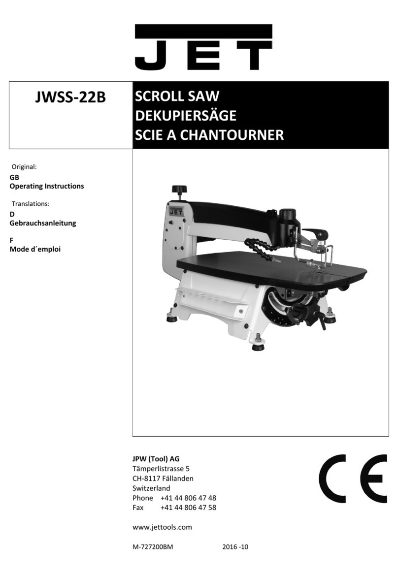
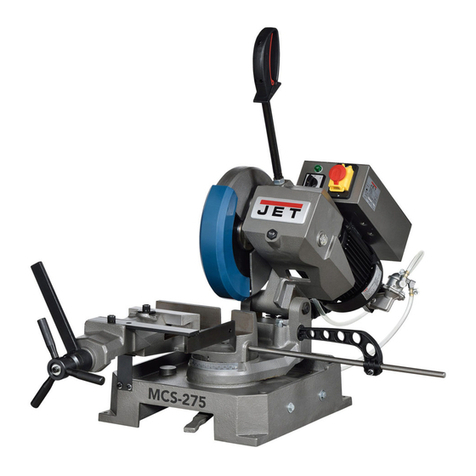
Jet ELITE EVTBS16V-230 Service manual

Operating Instructions and Parts Manual
Vertical Tilting Band Saw
Models EVTBS16V-230, EVTBS16V-460
JET®
427 New Sanford Road
LaVergne, Tennessee 37086
www.jettools.com
Ph.: 855-336-4032
Part No. M-891200
EDITION 2 05/2022
Copyright © 2022 JET
891200_EVTBS16V Tilting Band Saw_Edition 1.indd 1891200_EVTBS16V Tilting Band Saw_Edition 1.indd 1 5/10/22 10:22 AM5/10/22 10:22 AM

2
Vertical Tilting Band Saw
1.0 TABLE OF CONTENTS
1.0 TABLE OF CONTENTS................................................................................................................................2
2.0 IMPORTANT SAFETY INSTRUCTIONS......................................................................................................3
3.0 INTRODUCTION ..........................................................................................................................................6
4.0 SPECIFICATIONS........................................................................................................................................7
5.0 MACHINE DIMENSIONS .............................................................................................................................9
6.0 MACHINE TRANSPORT............................................................................................................................10
6.1 Shipping Contents................................................................................................................................10
7.0 SPOTTING and INSTALLATION ................................................................................................................ 11
7.1 Equipment Setting................................................................................................................................12
8.0 ELECTRICAL CONNECTIONS..................................................................................................................12
8.1 Three-Phase Test Run .........................................................................................................................12
9.0 CONTROL PANEL DESCRIPTION ............................................................................................................13
10.0 SET UP AND OPERATION PREPARATIONS............................................................................................13
10.1 Blade Installation..................................................................................................................................13
10.2 Blade Tracking Adjustment ..................................................................................................................14
10.3 Head Tilt Adjustment ............................................................................................................................14
10.4 Vise Plate Positioning ..........................................................................................................................14
10.5 Feeding Stroke.....................................................................................................................................15
10.6 Blade Speed Adjustment......................................................................................................................16
10.7 Feed Force Adjustment........................................................................................................................16
10.8 Upper Blade Guide Adjustment............................................................................................................16
10.9 Adjusting Cutter Head Weight..............................................................................................................17
10.10 Alignment Blade Squareness:..............................................................................................................17
10.11 Blade Guide Bearings Adjustment .......................................................................................................17
11.0 BAND SAW OPERATION...........................................................................................................................18
11.1 Blade Break-In Procedure....................................................................................................................18
11.2 Pre-Operation Checklist.......................................................................................................................18
11.3 Operation Procedure............................................................................................................................19
11.4 EvaluatingCuttingEfciency ...............................................................................................................19
12.0 MAINTENANCE .........................................................................................................................................20
12.1 Inspection And Service Schedule ........................................................................................................20
12.2 Lubrication Schedule ...........................................................................................................................20
12.3 Accessing And Cleaning The Coolant System.....................................................................................21
12.4 Pneumatic Care ..................................................................................................................................21
13.0 TROUBLESHOOTING ...............................................................................................................................22
13.1 Operating Problems .............................................................................................................................22
13.2 Mechanical and Electrical Problems ....................................................................................................23
13.2 Mechanical and Electrical Problems (cont.).........................................................................................24
14.0 SPEED AND PITCH CHART......................................................................................................................25
15.0 REPLACEMENT PARTS — EVTBS16V ....................................................................................................26
16.0 WIRING DIAGRAM — EVTBS16V.............................................................................................................46
17.0 HYDRAULICS / PNEUMATICS — EVTBS16V ..........................................................................................47
18.0 WARRANTY AND SERVICE ......................................................................................................................48
891200_EVTBS16V Tilting Band Saw_Edition 1.indd 2891200_EVTBS16V Tilting Band Saw_Edition 1.indd 2 5/10/22 10:22 AM5/10/22 10:22 AM

3
EVTBS16V
Read and understand the entire instruction manual before operating machine.
This band saw is designed and intended for use by properly trained and experienced personnel only. If you are not
familiar with the proper and safe operation of a band saw, do not use until proper training and knowledge has been
obtained.
WARNING – To reduce risk of injury:
1. Read and understand the warnings posted on the machine and in this manual. Failure to comply with all of these warnings
may cause serious injury.
2. Replace the warning labels if they become obscured or removed.
3. Do not use this band saw for other than its intended use. If used for other purposes, JET®, disclaims any real or implied
warranty and holds itself harmless from any injury that may result from that use.
4. Always wear approved safety glasses/face shields while using this band saw. Everyday eyeglasses only have impact resistant
lenses; they are not safety glasses.
5. Before operating this band saw, remove your tie, rings, watches and other jewelry, and roll sleeves up past the elbows. Remove
alllooseclothingandconnelonghair.Non-slipfootwearoranti-skidoorstripsarerecommended.Donotweargloves.
6. Wear ear protectors (plugs or muffs) during extended periods of operation.
7. Donotoperatethismachinewhiletiredorundertheinuenceofdrugs,alcoholoranymedication.
8. Make certain the switch is in the OFF position before connecting the machine to the power supply.
9. Make certain the machine is properly grounded.
10. Make all machine adjustments or maintenance with the machine unplugged from the power source.
11. Remove adjusting keys and wrenches. Form a habit of checking to see that keys and adjusting wrenches are removed from
the machine before turning it on.
12. Avoid contact with coolant, especially guarding your eyes.
13. Alwayskeephandsandngersawayfromthebladewhenthemachineisrunning.
14. Never hand hold the material. Always use the vise and clamp it securely.
15. Deburr sharp edges before handling or cutting.
16. Always provide adequate support for long and heavy material.
17. Keep safety guards in place at all times when the machine is in use. If removed for maintenance purposes, use extreme
caution and replace the guards immediately after maintenance is complete.
18. Check damaged parts. Before further use of the machine, a guard or other part that is damaged should be carefully checked
to determine that it will operate properly and perform its intended function. Check for alignment of moving parts, binding of
moving parts, breakage of parts, mounting and any other conditions that may affect its operation. A guard or other part that is
damaged should be properly repaired or replaced.
19. Do not use power tools in damp/wet locations or other dangerous environments. Do not expose them to rain. Keep work area
well lit. Provide for adequate space surrounding the work area and non-glare overhead lighting.
20. Keeptheooraroundthemachinecleanandfreeofscrapmaterial,oilandgrease.
21. Keep visitors a safe distance from the work area. Keep children away. Workshop should be childproof; padlocks, master switches,
remove starter keys.
2.0 IMPORTANT SAFETY INSTRUCTIONS
891200_EVTBS16V Tilting Band Saw_Edition 1.indd 3891200_EVTBS16V Tilting Band Saw_Edition 1.indd 3 5/10/22 10:22 AM5/10/22 10:22 AM

4
Vertical Tilting Band Saw
WARNING: This product can expose you to chemicals including titanium dioxide which is known to the State of
California to cause cancer, and lead which is known to the State of California to cause cancer and birth defects or other
reproductive harm. For more information go to http://www.p65warnings.ca.gov.
WARNING: Some dust, fumes and gases created by power sanding, sawing, grinding, drilling, welding and other
construction activities contain chemicals known to the State of California to cause cancer and birth defects or other
reproductive harm. Some examples of these chemicals are:
• lead from lead based paint
• crystalline silica from bricks, cement and other masonry products
• arsenic and chromium from chemically treated lumber
Your risk of exposure varies, depending on how often you do this type of work. To reduce your exposure to these chemicals,
workinawell-ventilatedareaandworkwithapprovedsafetyequipment,suchasdustmasksthatarespecicallydesigned
tolteroutmicroscopicparticles.Formoreinformationgotohttp://www.p65warnings.ca.gov/and http://www.p65warnings.
ca.gov/wood.
22. Give your work your undivided attention. Looking around, carrying on a conversation and “horse-play” are careless acts that
can result in serious injury.
23. Maintain a balanced stance at all times so that you do not fall or lean against the blade or other moving parts. Do not overreach
or use excessive force to perform any machine operation.
24. Use the right tool at the correct speed and feed rate. Do not force a tool or attachment to do a job for which it was not designed.
The right tool will do the job better and more safely.
25. Use recommended accessories; improper accessories may be hazardous.
26. Maintain tools with care. Keep the blade sharp and clean for the best and safest performance. Follow instructions for lubricating
and changing accessories.
27. Maintain proper adjustment of blade tension, blade guides and thrust bearings.
28. Turn off the machine and disconnect from power before cleaning. Use a brush to remove chips or debris — do not use your
hands.
29. Do not stand on the machine. Serious injury could occur if the machine tips over.
30. Never leave the machine running unattended. Turn the power off and do not leave the machine until it comes to a complete
stop.
31. Be sure that the blade is not in contact with the workpiece when the motor is started. The motor shall be started and you should
allow the saw to come up to full speed before bringing the saw blade into contact with the workpiece.
32. Adjustupperguidetoclearworkpiece.Holdworkpiecermlyagainstthetable.
33. Direction of feed — feed work into a blade or cutter against the direction of rotation of the blade or cutter only.
34. Installation work and electrical wiring must be done by a qualied electrician in accordance with all applicable codes and
standards.
35. Do not remove jammed pieces until blade has stopped.
36. Do not bypass or defeat safety interlock systems.
891200_EVTBS16V Tilting Band Saw_Edition 1.indd 4891200_EVTBS16V Tilting Band Saw_Edition 1.indd 4 5/10/22 10:22 AM5/10/22 10:22 AM

5
EVTBS16V
2.1 Warning Labels
!
This means that if precautions are not heeded, it may
result in minor injury and/or possible machine dam-
age.
!
This means that if precautions are not heeded, it may
result in serious or even fatal injury.
Familiarize yourself with the following safety notices used in this manual:
Replace warning labels if they become obscured or
removed.
- Keep hands and other body parts away from a running
blade.
- Do not open the blade cover while machine is running.
- Do not store combustible materials near or around
machine.
- Always wear approved safety glasses/face shields while
using this machine.
- Keep machine guards in place at all times.
- Do not wear gloves.
-Removelooseclothingandconnelonghair.
- Keep the work area clean and free of miscellaneous
objects.
891200_EVTBS16V Tilting Band Saw_Edition 1.indd 5891200_EVTBS16V Tilting Band Saw_Edition 1.indd 5 5/10/22 10:22 AM5/10/22 10:22 AM

6
Vertical Tilting Band Saw
3.0 INTRODUCTION
This manual is provided by JET®covering the safe operation and maintenance procedures for a JET Model EVTBS16V Tilt-
ing Band Saw. This manual contains instructions on installation, safety precautions, general operating procedures, mainte-
nance instructions and parts breakdown. Your machine has been designed and constructed to provide consistent, long-term
operation if used in accordance with the instructions as set forth in this document.
If there are questions or comments, please contact your local supplier or JET. JET can also be reached at our web site:
www.jettools.com/us/en/elite.
Retain this manual for future reference. If the machine transfers ownership, the manual should accompany it.
Mail in the provided registration card, or register online:
http://www.jettools.com/us/en/service-and-support/warranty/registration/
NOTE: Illustrations in this manual may not always show your exact model.
891200_EVTBS16V Tilting Band Saw_Edition 1.indd 6891200_EVTBS16V Tilting Band Saw_Edition 1.indd 6 5/10/22 10:22 AM5/10/22 10:22 AM

7
EVTBS16V
Model Number EVTBS16V-230 EVTBS16V-460
Stock Number 891200 891210
Motor and Electricals
Main motor type Totally enclosed, fan-cooled, AC induction
Horsepower 2 HP (1.5kW)
Phase 3 phase
Voltage prewired 230V prewired 460V
Cycle 60 Hz
Listed FLA (full load amps) 6.5 A 3.25 A
Starting amps/inrush current 23 A 12.5 A
Running amps, no load 1.1 A 0.6 A
Motor speed 1720 RPM
On/off switch magnetic, pushbutton with E-stop
Power transfer Gear reducer
Gearbox ratio 1:30
Power cable (unattached) 14AWGx3C, 6 ft., no plug
Recommended circuit size 15 A
Sound emission 70 dB at 3 ft. from machine
Coolant pump 32W, 230V 1PH, 2P, 2800RPM, 0.25A
Capacities
Round
90 deg. 16 in. (406mm)
45 deg. (R) 13-1/4 in. (337mm)
45 deg. (L) 11-1/2 in. (292mm)
Square
(WxH)
90 deg. 16 x 16 in. (406 x 406mm)
45 deg. (R) 13-1/4 x 13-1/4 in.(337 x 337mm)
45 deg. (L) 11-1/2 x 11-1/2 in. (292 x 292mm)
Rectangle
(WxH)
90 deg. 20 x 16 in. (508 x 406mm)
45 deg. (R) 13-1/4 x 16 in.(337 x 406mm)
45 deg. (L) 11-1/2 x 16 in. (292 x 406mm)
Blade (WxTxL) 1-1/16 x 0.035 x 168-1/2” 4/6T Lenox
Blade wheel size (Dia. x W) 18.11”(460mm)
Blade speed (SFPM) variable within 76~430
Cuttinguid/coolanttank 60 L
Main materials
Stand Steel
Bow Steel
Blade wheels Cast iron
Bed Cast iron
Vise jaws Cast iron
4.0 SPECIFICATIONS
891200_EVTBS16V Tilting Band Saw_Edition 1.indd 7891200_EVTBS16V Tilting Band Saw_Edition 1.indd 7 5/10/22 10:22 AM5/10/22 10:22 AM

8
Vertical Tilting Band Saw
EVTBS16V-230 EVTBS16V-460
General dimensions
Heightofbedfromoor 39-3/8”(1000mm)
Overall dimensions (LxWxH 94.5 x 49.2 x 90.55 in. (2400 x 1250 x 2300mm)
Shipping dimensions (LxWxH) 83.5 x 38.18 x 92.91 in. (2120L x 970W x 2360Hmm)
Weights
Net weight (approx.) 1408 lbs (640kg)
Shipping weight (approx.) 1584 lbs (720kg)
The specications in this manual were current at time of publication, but because of our policy of continuous improvement,
JET®, reserves the right to change specications at any time and without prior notice, without incurring obligations.
891200_EVTBS16V Tilting Band Saw_Edition 1.indd 8891200_EVTBS16V Tilting Band Saw_Edition 1.indd 8 5/10/22 10:22 AM5/10/22 10:22 AM

9
EVTBS16V
5.0 MACHINE DIMENSIONS
891200_EVTBS16V Tilting Band Saw_Edition 1.indd 9891200_EVTBS16V Tilting Band Saw_Edition 1.indd 9 5/10/22 10:22 AM5/10/22 10:22 AM

10
Vertical Tilting Band Saw
6.0 MACHINE TRANSPORT
6.1 Shipping Contents
Item Description
Cross driver 1 piece
Flat driver 1 piece
17/19 Open wrench 1 piece
12/14 Open wrench 1 piece
4/5/6/8 Hex wrench 1 piece
M12x45 Hex Cap Screw 4 pieces
M12 Nut 4 pieces
Note: DO NOT use alternate lift points.
891200_EVTBS16V Tilting Band Saw_Edition 1.indd 10891200_EVTBS16V Tilting Band Saw_Edition 1.indd 10 5/10/22 10:22 AM5/10/22 10:22 AM

11
EVTBS16V
7.0 SPOTTING AND INSTALLATION
Note: Read and understand the entire manual before
attempting setup or operation.
1. Finish uncrating the saw and inspect for damage. Should
any damage have occurred, immediately contact your
local distributor and shipping agent.
2. Remove the four (4) nuts and washers holding the band
saw to the pallet.
3. Use the four lifting rings to lift the band saw to its permanent
location. See section 6.0. For best performance, the
machine should be located on a solid and level concrete
foundation. Allow room for servicing and for moving large
stock around the band saw when deciding a location for
the machine.
4. Attach the base frame cover (Fig. 1). Install the M12 nuts
(4pcs).Installthehexheadscrewsandatwashersinto
the saw base, then tighten using a 19mm wrench.
Fig. 3
5. To level the machine, place a level on the table and
observe in both directions.
6. Anchoringthe machine to theconcrete oor is highly
advised (B, Fig. 1A).
7. An alternative to anchoring is to use metal plates or
shims. Use a metal shim under each leveling bolt (Fig.
1A).
8. To level, adjust the bolts on each corner (A, Fig. 1) until
the unit is level in both directions. Tighten the jam nuts
against the mounting foot.
9. Remove the red shipping bracket (C, Fig. 2).
10. Loosen the two (2) set screws underneath the table
preventing the carriage from sliding during shipment (D,
Fig. 3). Loosen these with a 6mm hex wrench.
11. Remove any preservatives from exposed metal surfaces
with a cleaner/degreaser. Do not use gasoline, paint
thinner, or any cellulose-based product, as these will
damage painted surfaces.
A
Fig. 1
Fig. 2
Fig. 1A
891200_EVTBS16V Tilting Band Saw_Edition 1.indd 11891200_EVTBS16V Tilting Band Saw_Edition 1.indd 11 5/10/22 10:22 AM5/10/22 10:22 AM

12
Vertical Tilting Band Saw
8.0 ELECTRICAL CONNECTIONS
!
All electrical connections must be done by a
qualied electrician in compliance with all relevant
codes. This machine must be properly grounded to
help prevent serious or fatal injury.
7.1 Equipment Setting
1. Fill the coolant reservoir with 18 gallons of the appropriate
coolant.
2. Acompressedairlineshouldbeconnectedtothelterat
the back of the saw (Fig. 5).
3. Use clean dry air regulated from 0.5 – 1.0CFM @ 80 –
100psi(.55–.69MPa),supplyairtotheairlterthrough
the 1/4” NPT inlet port.
4. Drainany accumulatedmoisture withinthe lter at least
monthly.
5. Reference section 17.0, Pneumatics / Hydraulics for the
compressed air diagram.
Fig. 5
The EVTBS16V is wired for 3-phase, 230V, or 3-phase
460V, depending on your model.
This tool should be connected to a grounded metal
permanent wiring system; or to a system having an
equipment-grounding conductor. The band saw must be
grounded. A qualied electrician can make the proper
electricalconnectionsandconrmthatthepoweronsiteis
compatible with the saw.
Before connecting to the power source, make sure the
switch is in the OFF position.
8.1 Three-Phase Test Run
After wiring the band saw, you should check that the wires
have been connected properly. Connect the machine to
the power source and turn it on for an instant to watch the
direction of the blade movement.
If the blade runs upward instead of downward, disconnect
the machine from the power, and switch any two of the
three leads in the motor junction box (see section 16.0,
Wiring Diagram).
EXCESS
COOLANT
OVERFLOW
Fig. 4
891200_EVTBS16V Tilting Band Saw_Edition 1.indd 12891200_EVTBS16V Tilting Band Saw_Edition 1.indd 12 5/10/22 10:22 AM5/10/22 10:22 AM

13
EVTBS16V
10.0 SET UP AND OPERATION
PREPARATIONS
9.0 CONTROL PANEL
DESCRIPTION
Reference Figure 6
A: EMERGENCY STOP SWITCH:
Press to immediately stop all machine functions. To
restart machine, twist it clockwise (CW) until the button
disengages.
B: LIGHT SWITCH:
Turn work light on and off.
C: COOLANT SWITCH:
Turnarrowto“I”toturnoncoolantow.Turnarrowto“O”
tostopcoolantow.
D: STOP BUTTON:
Press to stop band saw blade.
E: BLADE FEED SWITCH:
Press the switch to follow blade feed action.
F: BLADE SPEED READOUT:
Identiesbladespeedinsurfacefeetperminute.
G: BLADE SPEED CONTROL KNOB:
Turn this knob clockwise (CW) to increase blade speed.
H: START BUTTON:
Press to start band saw blade.
I: POWER INDICATOR LIGHT:
Illuminates whenever machine is powered On.
Fig. 6
A
B C D E
F
G
H
IFig. 7
10.1 Blade Installation
1. Make certain the cutting head is locked
in the vertical position.
2. Unlock the clamps on both the upper
and lower blade wheel housings and
open the covers.
3. Uncoil a blade. Route the blade around
the blade wheels, through each of the
guards, and through both blade guide
assemblies.
4. Slide the blade on the wheels so the
back edge of the blade is approximately
1/32”fromthebackangeofthewheel.
Check the teeth on the portion of the
blade between the upper and lower
blade guides to see that they point down
toward the table (Fig. 7).
5. Tension the blade by turning the tension
handle counterclockwise (CCW). (The
factory set is 1400 kgs/cm2.) Before
proceeding, make sure all guards and
covers are in place and secured.
6. Turn the feed force to “0”. Push the START button on
control panel and let the blade spin several times around
the blade wheels.
7. Push the STOP button on the control panel. Check to
see if the back edge of the blade has maintained an
approximate 1/32” gap from the ange on the back of
blade wheels. If the blade rides against the ange or is
more than 1/32” away from the ange, adjust the lower
wheel tilt angle as follows (use hex wrenches to adjust the
three M10 set screws).
8. Once the blade has been installed, tensioned and tracked
properly on the wheels, close the upper and lower covers.
Lock the clamps and secure all guards in place.
!
All adjustments or repairs to machine must be done
with power off and machine disconnected from
power source. Failure to comply may cause serious
injury.
891200_EVTBS16V Tilting Band Saw_Edition 1.indd 13891200_EVTBS16V Tilting Band Saw_Edition 1.indd 13 5/10/22 10:22 AM5/10/22 10:22 AM

14
Vertical Tilting Band Saw
10.2 Blade Tracking Adjustment
Typically, the blade should track with the back edge of
the blade maintaining an approximate 1/32" gap from the
angeonthebackofbladewheels.
1. Loosen the three (3) hex head mounting bolts (A, Fig. 8)
on the back side of the lower wheel housing 1 to 1-1/2
turns.
2. Adjust the set screw (B, Fig. 8) to change the tracking of
the blade.
3. When the tracking is correct, evenly tighten the three (3)
hex head screws.
4. Check the tracking again.
10.3 Head Tilt Adjustment
1. The cutting head is adjustable to make angled cuts from
-45° to +45°. Be sure the upper blade guide will clear
any obstructions on the table before adjusting the cutting
head angle.
2. To adjust the cutting head angle, turn the lock handle
counterclockwise (CCW) (C, Fig. 9).
3. Holding the cutting head handle, tilt the head to desired
angle (D, Fig. 9).
4. When the desired angle is obtained, turn the lock handle
clockwise (CW) to secure the cutting head for operation.
10.4 Vise Plate Positioning
Reference Figures 10 and 11.
The vise system consists of two (2) interchangeable vise
plates and a quick clamp. One vise plate is mounted as the
stationary (rear) vise plate (E) and the other is mounted as the
movable (front) vise plate (F). The quick clamp is mounted in
the T-slot inline with and attached to the front vise plate.
The vise plates may be mounted on either side of the blade
and with either the square or angled edge toward the blade.
The quick clamp is moved to align with the plate which is
being used as the movable (front) plate.
The following gives only one example of how the vise plates
can be mounted to the saw table.
Fig. 8
Fig. 9
1. Place the rear vise plate in the T-slot and at a position on
the table so that the hold down bolts (I) are aligned with
the threaded mounting holes in the tabletop.
2. Use a hex key to secure the rear vise plate to the tabletop
with the hold down bolts (I).
3. Place the front vice plate in the T-slot, opposite the rear vise
plate.Thiswillbeviseplateatsurfacetoatsurface.
4. Place the quick clamp assembly into the T-slot aligned with
thefrontviseplatewiththeatthreadedendagainstthe
vise plate and the ball knob (G) outward for the operator.
This assembly may be positioned as needed to allow for
clamping and releasing the vise plate.
5. Insert the M8 x25 socket head screw (J) through the plate
and into the slide bar for the quick clamp.
Fig. 10
A
B
A
D
C
EJK
G
I
FH
891200_EVTBS16V Tilting Band Saw_Edition 1.indd 14891200_EVTBS16V Tilting Band Saw_Edition 1.indd 14 5/10/22 10:22 AM5/10/22 10:22 AM
15
EVTBS16V
6. The lock handle (K, Fig. 10) secures the clamp assembly
to the table T-slot.
7. Pulling the release handle (H, Fig. 10) unlocks the slide
bar, allowing the front plate to be moved to clamp or
unclamp the material. Pushing the release handle forward
presses the slide bar forward slightly, locking the slide
bar.
8. Figure 11 shows an optional clamping procedure to use
when working with large diameter pieces. Use the vise
plates to support and align the workpiece. Then use the
ratchet straps (L, Fig. 11) hooked on the edge of the
table to secure the workpiece and prevent unintended
movement.
10.5.2 Saw Head Movement - Automatic
1. The saw also can be fed forward automatically by
adjusting the feed force. Pull upward on the knob (N,
Fig. 13) and rotate clockwise (CW) or counterclockwise
(CCW) until the desired feed is obtained.
2. Observe the chips to determine when the feed is
correct.
3. Press down on the adjustment knob to lock the setting.
Fig. 11
L
L
Fig. 12
M
10.5.3 Saw Head Movement - Travel Limits
1. The travel stops are generally used when cutting
multiple pieces to the same length.
2. The contact block (O, Fig. 14) contacts and actuates
the travel limit switches.
3. The retract travel stop (P, Fig. 14) is set at the factory
and is not normally adjusted.
4. The forward stop (Q, Fig. 14) should be adjusted about
1/8" - 1/4" past the point where the blade exits a cut.
Fig. 13
N
10.5 Feeding Stroke
Reference Figures 12, 13, and 14.
11.5.1 Saw Head Movement - Manual
The cutting head can be fed forward or backwards manually
by rotating the feed handle (M, Fig. 12) counterclockwise
(CCW) or clockwise (CW), respectively.
!
The lock handle (K) must be tight and the workpiece
clamped with the release handle (H) locked during
any cutting to prevent unintended movement.
891200_EVTBS16V Tilting Band Saw_Edition 1.indd 15891200_EVTBS16V Tilting Band Saw_Edition 1.indd 15 5/10/22 10:22 AM5/10/22 10:22 AM

16
Vertical Tilting Band Saw
3. Hold the saw head in this position and slide the forward
stopbackuntilitrmlycontactsthecontactblock.
4. During normal cutting, when the contact block (O, Fig. 14)
contacts the forward stop (Q, Fig. 14), the cutting head
will automatically stop its forward movement, the blade
will shut off, and the saw head will retract to the start
position.
5. The retract stop should be adjusted so that the saw head
stops at a position that has the blade retracted out of the
cut area and before it reaches the full retracted physical
limits.
10.6 Blade Speed Adjustment
1. Always set the feed force to “0” before adjusting the blade
speed.
2. Push the START button on the control panel.
3. If the carriage still moves forward, adjust the feed
force knob counterclockwise (CCW) until it remains
stationary.
4. Push the STOP button. You are now ready to adjust the
blade speed.
5. The blade speed readout on the control panel displays
the blade speed in surface feet per minute. Choice of
blade speed depends on the type and thickness of metal
being cut. Reference Table 1 for the recommended blade
speeds.
Fig. 14
Q
O
P
To adjust:
1. Loosen the forward travel adjustment handle (Q, Fig. 14)
and slide the adjustment block forward to allow the saw
head to travel forward to simulate the complete cut plus
1/8" - 1/4".
2. Using the manual saw head feed handwheel, move the
saw head forward until the teeth of the blade are forward
far enough to have cut the material plus 1/8" - 1/4". This
will ensure that the material is cut complete.
6. Push the START button on the control panel. Twist the
blade speed control knob clockwise (CW) to increase the
blade speed, counterclockwise (CCW) to reduce blade
speed.
7. Once the proper blade speed is obtained, push the STOP
button on the control panel. Both blade speed and feed
force may be adjusted as necessary while the blade is
cutting.
Recommended Speed for Cutting Various Materials
SPEED FPM MATERIAL TO BE CUT
76 – 100 TOOL STEEL, STAINLESS STEEL,
HARD BRONZE, HARD CAST IRON
100 – 150 MILD STEEL, SOFT CAST IRON,
MEDIUM HARD BRASS AND BRONZE
150 – 250 SOFT BRASSES AND BRONZES,
HARD ALUMINUM, PLASTIC
250 – 430 PLASTICS, SOFT ALUMINUM, WOOD,
OTHER LIGHT MATERIALS
Table 1
10.7 Feed Force Adjustment
1. Feed force is indicated by the dial gauge above the feed
force knob.
RECOMMENDED FEED FORCE
Speed FPM Material (solid) Feed Force (PSI)
76-100 up 5" 15-20
100-150 5" to 8" 25-50
150-250 9"to 10" 50-60
250-430 over 10" 60-70
Table 2
2. Reference Table 2 for recommended feed force settings.
Twist the feed force knob to increase or decrease the feed
force setting.
10.8 Upper Blade Guide Adjustment
The upper blade guide assembly should be adjusted down
as close to the workpiece as possible without interfering
with the workpiece or vice clamps.
1. To adjust the arm up or down, grasp the handwheel of the
upper blade guide.
2. Loosen the locking handle (R, Fig. 15) and rotate the
handwheel (S, Fig. 15) to lift or lower the guide to the
desired height.
3. Hold the guide in this position and tighten the locking
handle (R, Fig. 15).
891200_EVTBS16V Tilting Band Saw_Edition 1.indd 16891200_EVTBS16V Tilting Band Saw_Edition 1.indd 16 5/10/22 10:22 AM5/10/22 10:22 AM

17
EVTBS16V
10.9 Adjusting Cutter Head Weight
Adjusting the weight of the cutter head helps provide
support of the head during tilting.
Use the manual handwheel to move the cutting head
forward to the stop limit. If additional space is needed,
adjust the forward stop limit to allow travel fully forward.
Tightening the M12 x 90L bolt (T, Fig. 16) will increase the
tension on the springs which will thereby decrease the
balance weight of the cutting head.
Loosening the M12 x 90L bolt (T, Fig. 16) will decrease
the tension on the springs which will thereby increase the
balance weight of the cutting head.
10.10 Alignment Blade Squareness:
1. To check, move the upper blade guide to its uppermost
position.
2. Use a square (U, Fig. 17) to check that the blade is
perpendicular to the tabletop.
3. If alignment is necessary, loosen the two (2) bolts (V, Fig.
17) holding the lower blade guide assembly.
4. Move the lower blade guide block (W, Fig. 17) to the left or
right as necessary.
5. Retighten the two (2) bolts loosened in Step 3.
Fig. 15
S
R
Fig. 16
T
Fig. 17
U
V
10.11 Blade Guide Bearings Adjustment
Reference Figure 18.
For this procedure, “Left” and “Right” are based upon
standing in front of the saw looking directly at the
teeth of the saw blade. Similar to the angle shown in
Fig. 18.
1. From the angle shown in Fig. 18, the guide to the left of the
blade is on a concentric shaft. The guide to the right of the
blade is on an eccentric shaft. The eccentric shaft (right) is
the shaft that will be adjusted.
2. Loosen the lock nut (X, Fig. 18) with a 12 mm open end
wrench while holding the adjuster with a 14 mm open end
wrench.
W
!
Blade guides must be properly adjusted or damage
may occur to the blade and/or guides.
891200_EVTBS16V Tilting Band Saw_Edition 1.indd 17891200_EVTBS16V Tilting Band Saw_Edition 1.indd 17 5/10/22 10:22 AM5/10/22 10:22 AM

18
Vertical Tilting Band Saw
3. Turn the adjuster (Y, Fig. 18) to adjust the bearing. The
bearing should barely touch the blade (0.003"). This
clearance can be measured with a piece of thin paper
whichshouldjusttintothegapbetweenthebearingand
the blade.
4. Tighten the lock nut (X, Fig. 18).
5. Set the lower blade guide bearing in the same manner.
6. When correct guide bearing adjustment is done, the blade
runs smoothly and evenly without twisting or snagging
anywhere along its path.
Fig. 18
X
Y
11.0 BAND SAW OPERATION
ConsultSection9.0foridenticationofthecontrols.
11.1 Blade Break-In Procedure
New blades are very sharp and therefore have a tooth
geometry that is easily damaged if a careful break-in
procedure is not followed. Consult the blade manufacturer’s
literatureforbreak-inofspecicbladesonspecicmaterials.
The following procedure will be adequate, however, for
break-in of JET-supplied blades on lower alloy ferrous
materials.
1. Use a section of round stock.
2. Operate the saw at low speed. Start the cut with a very
light feed rate.
3. When the saw has completed about 1/3 of the cut, increase
the feed rate slightly and allow the saw to complete the
cut.
4. Keep the feed rate at the same setting and begin a second
cut on the same or similar workpiece.
5. When the saw has completed about 1/3 of the cut,
increase the feed rate while watching the chip formation
untilcuttingisatitsmostefcientrate(referenceSection
11.4 - “Evaluating Cutting Efciency”). Allow the saw to
complete the cut.
6. The blade is now considered ready for use.
11.2 Pre-Operation Checklist
The following items should be checked at the beginning
of each shift and by each new operator. This checklist is
designed to maintain peak saw performance, increase
blade life, reduce saw repairs, and provide a safe machine
for the operator.
• Guards and covers in place and closed securely.
• Checkthehydraulicuidlevel-llasnecessary.
• Remove any unnecessary tools and equipment from
the work surfaces and work area.
• Inspect blade-wheels and blade guides - be sure to
remove chips. Check that the blade cleaning brush is
aligned with the blade. Replace the blade brush if worn.
• Inspect the blade - replace if worn or if missing teeth.
• Check that the proper blade is installed.
• Check the blade tension - adjust if needed.
• Visually inspect the saw for damage or leaks. REPAIR
BEFORE OPERATING.
• Check cutting uid - add as necessary, change if
contaminated.
891200_EVTBS16V Tilting Band Saw_Edition 1.indd 18891200_EVTBS16V Tilting Band Saw_Edition 1.indd 18 5/10/22 10:22 AM5/10/22 10:22 AM

19
EVTBS16V
!
Never operate band saw without blade and wheel
covers in place and secured.
!
Material longer than the table must be properly
supported to prevent unintended movement.
11.3 Operation Procedure
Operation of this band saw is quite simple once the function
of each control and feature is understood.
1. Turn the main disconnect switch to On and allow the
system to boot up.
2. Twist and release the Emergency Stop Switch.
3. Turn the LAMP ON/OFF switch to the ON position.
4. Raise the guide arm high enough to clear the material. If
tilting the bow to the left. This will also need to clear the
vise.
5. Determine the angle of the cut. Use the lock lever to
loosen the saw bow and manually tilt the bow from 45° left
tilt to 45° right tilt. Never rely solely on the scale markers
for the correct tilt angle. Always verify the angle with a
protractor.
6. Mark the material for the location and angle of the cut.
7. Place the material between the vise plates. The vise
may be positioned on either side of the cut and has other
forward and aft adjustments.
8. Align the cut mark with the saw blade.
9. Close the vise to clamp the material.
10. Turn the coolant switch to On to start the coolant ow.
Adjusttheowatthenozzleusingtheballvalvelocated
at the nozzle.
11. Press the START switch to start the saw blade and
advance the saw bow into the cut.
NOTE: Reference Table 4 - Speed and Pitch chart in Section
14.0. Select the speed setting for the material to be cut.
12. Adjust the saw blade speed using the adjustment knob
on the right side of the console and monitoring the speed
using the blade speed indicator. Set the speed so that the
speed is ±5 SFPM of the desired setting. Getting an exact
matchwillbedifcult.
13. Set the feed pressure to a pressure as recommended in
pressure chart, Table 2 - Recommended Feed Force.
14. Press the “STOP” button to stop the bow movement if
necessary. The saw bow will advance until the forward
stop limit switch is engaged. The saw blade will then stop,
the frame will retract to the home position and wait for the
next cut cycle.
15. Slowly turn the feed speed knob counterclockwise (CCW)
until the feed speed is set. This value is the “Cutting Rate”
from the Cutting Chart. It is listed in Surface Inches Per
Minute (SIPM).
16. Once the feed rate and pressure cutting rate are set,
lightly tighten the lock knobs to hold these setting. This
will keep the settings for as long as the same material is
to be cut.
17. When the cut is complete, (either by the feed stroke limits
or by the operator pressing the STOP button) the saw
blade will stop and the saw bow will retract to the start
position.
18. Once the saw frame has returned to the home position, the
saw may be set for the next cut. This will be determined by
eachspecicprojecttobesawed.
NOTE:Itisrecommendedtochecktherstcutforaccuracy.
Make any adjustments before cutting the remaining stock.
If the saw frame is not set at 0° the saw will not cut squarely.
19. When the saw is not in operation, power the saw down by
pressing the E-Stop. If leaving the saw unattended, turn
the main disconnect to the Off position.
11.4 EvaluatingCuttingEfciency
The best way to determine whether a blade is cutting
efcientlyistoobservethechipsformedbythecutting.
• If chip formation is powdery, then the feed rate is too
light, or the blade is dull.
• If the chips formed are curled, but colored – blue or
straw colored from heat generated during the cut –
then feed rate is excessive.
• If chips are slightly curled and not colored by heat, then
thebladeissufcientlysharpandiscuttingatitsmost
efcientrate.
891200_EVTBS16V Tilting Band Saw_Edition 1.indd 19891200_EVTBS16V Tilting Band Saw_Edition 1.indd 19 5/10/22 10:22 AM5/10/22 10:22 AM

20
Vertical Tilting Band Saw
12.0 MAINTENANCE
!
Before doing maintenance on the machine, discon-
nect it from the electrical supply by pulling out the
plug or switching off the main switch. Failure to com-
ply may cause serious injury.
The maintenance jobs listed in this section, are divided
into daily, weekly, and monthly intervals. If the following
operations are neglected, the result will be premature wear
of the machine and poor performance.
Use a brush to loosen the accumulated chips and debris.
Use a shop vacuum to remove the debris. Make sure the
chip brush on the lower band wheel is properly adjusted.
If the power cord is worn, cut, or damaged in any way, have
it replaced immediately.
Wipe off the rubber tires, and clean the tables after each
day’s use.
12.1 Inspection and Service Schedule
12.1.1 Daily
• Check daily for any unsafe conditions and x
immediately.
• Check that all nuts and bolts are properly tightened.
• Give general cleaning to the machine to remove
accumulated shavings.
• Clean the lubricating coolant drain hole to avoid excess
uid.
• Top off the level of lubricating coolant.
• Check blade for wear.
• Drainanywaterbuildupfromtheairlter.
• Check functionality of the shields and emergency stops.
12.1.2 Weekly
• Lubricate threaded components and sliding devices.
• Lubricate the feed chain with SAE 30 oil.
• Apply rust inhibitive lubricant to all non-painted
surfaces.
• Thoroughly clean the machine to remove shavings,
especially from the coolant tank.
• Removal of pump from its housing, cleaning of the
suctionlterandsuctionzone.
• Clean the lter of the pump suction head and the
suction area.
• Use compressed air to clean the blade guides (guide
bearings and drain hole of the lubricating and cooling
tank).
• Cleanywheelhousingsandtheraceoftheywheels.
• Check and add coolant.
• Checkthehydraulicuidlevel.Movethecuttinghead
allthewayforwardandchecktheuidlevelindicator.
12.1.3 Monthly
• Check that the blade guide bearings on the heads are
in perfect running condition.
• Lubricate the lower blade guide pivot with a molybdenum
disuldegrease.
• Lubricate cutting head pivot collar (grease tting
attached on the carriage assembly) with a molybdenum
disuldegrease.
• Check the tightness of the screws for the motor, pump,
and accident protection guards.
12.1.4 Three Months
• Lubricate the blade tensioner screw and blade tension
slidingplatewithamolybdenumdisuldegrease.
• Replace the coolant.
12.1.5 Yearly
• Replacethehydraulicuid.Siphonuidoutandreplace
withSAE10Whydraulicuidwhilethecuttingheadis
all the way forward. Oil Disposal. Used oil products
must be disposed of in a proper manner following your
local regulations.
• Check blade alignment.
123.2 Lubrication Schedule
Upper Blade Guide Shaft – lightly grease weekly. Clean
after each day’s use.
Speed Change Handle–greasemonthlywithalightlm
on teeth and threads.
Variable Pulley - insert a light weight grease into the
greasettinglocatedontheendofthepulleyshaft.
Blade Tension Screw – grease monthly.
AII ball bearings are permanently lubricated and sealed.
They require no further lubrication.
891200_EVTBS16V Tilting Band Saw_Edition 1.indd 20891200_EVTBS16V Tilting Band Saw_Edition 1.indd 20 5/10/22 10:22 AM5/10/22 10:22 AM
This manual suits for next models
1
Table of contents
Other Jet Saw manuals

Jet
Jet HVBS-712K User manual

Jet
Jet JWBS-14 User manual

Jet
Jet VBS-3612 Service manual

Jet
Jet MBS-827DGVI User manual

Jet
Jet J-FK350-2 Service manual

Jet
Jet JTS-315LA User manual

Jet
Jet JWBS-18QT Service manual

Jet
Jet XACTA JTAS-12-DX Service manual

Jet
Jet JWBS-16B Service manual

Jet
Jet HVBS-712 Service manual
Popular Saw manuals by other brands

Yard force
Yard force LS F12 Original instructions

Workzone
Workzone M1Y-DU10-190 Original operating instructions

EINHELL
EINHELL NEW GENERATION KGSZ 3050 operating instructions

Hilti
Hilti DST 10-E operating instructions

RIDGID
RIDGID R4141 Operator's manual

Zipper Mowers
Zipper Mowers ZI-TKS 250H Operation manual