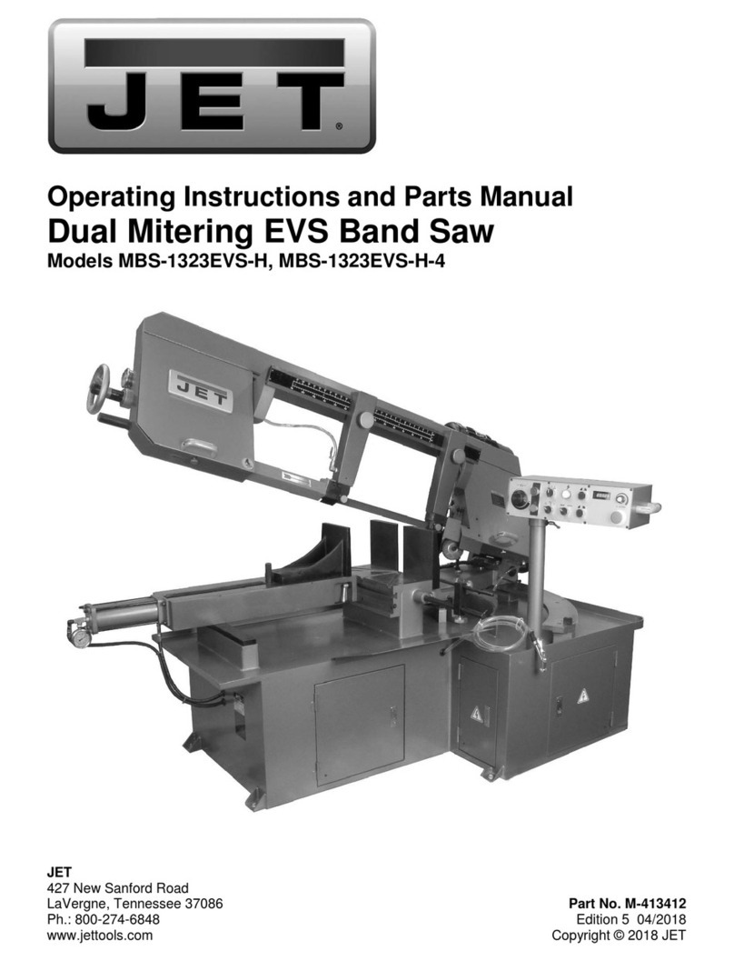
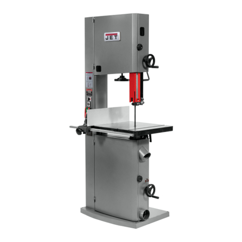
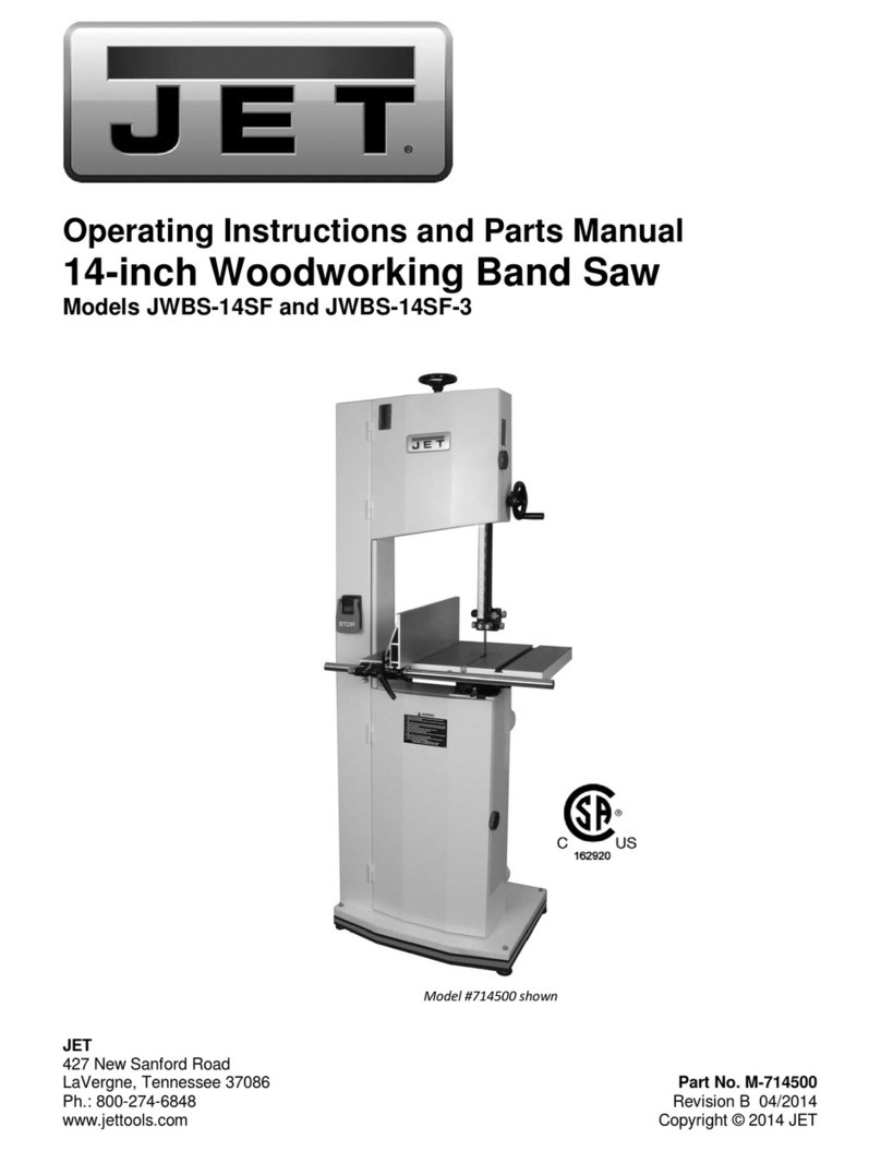
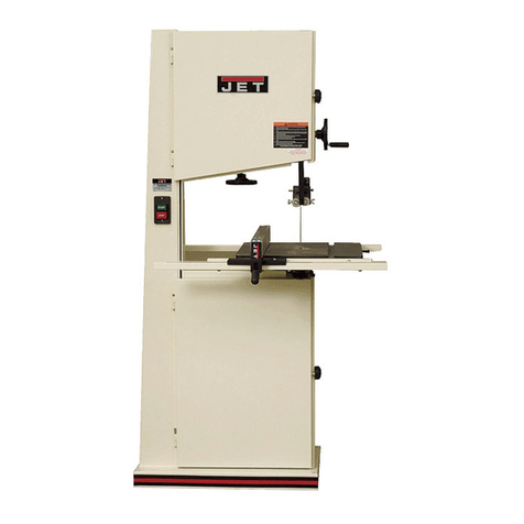
Jet JWBS-18 User manual

GB - ENGLISH
Operating Instructions
Dear Customer,
Many thanks for the confidence you have shown in us with the purchase of your new JET-machine. This manual has been prepared
for the owner and operators of a JET JWBS-15, JWBS-18, JWBS-20 band saw to promote safety during installation, operation and
maintenance procedures. Please read and understand the information contained in these operating instructions and the
accompanying documents. To obtain maximum life and efficiency from your machine, and to use the machine safely, read this manual
thoroughly and follow instructions carefully.
…Table of Contents
1. Declaration of conformity
2. Warranty
3. Safety
Authorized use
General safety notes
Remaining hazards
4. Machine specifications
Machine description
Technical data
Noise emission
Dust emission
Contents of delivery
5. Transport and start up
Transport and installation
Assembly
Mains connection
Dust connection
Starting operation
6. Machine operation
7. Setup and adjustments
Saw blade selection
Changing the saw blade
Blade tracking adjustment
Blade tension adjustment
Blade guide adjustment
Blade speed adjustment
Folding the bandsaw blade
8. Maintenance and inspection
9. Troubleshooting
10. Environmental protection
11. Available accessories
12. „Safe operation” ............ appendix A
1. Declaration of conformity
On our own responsibility we hereby declare that this
product complies with the regulations* listed on page 2.
Designed in consideration with the standards**. CE type
examination*** performed by****.
2. Warranty
JPW (Tool) AG guarantees that the supplied product is free
from material defects and manufacturing faults.
This warranty does not cover any defects which are
caused, either directly or indirectly, by incorrect use,
carelessness, accidental damage, repair, inadequate
maintenance or cleaning and normal wear and tear.
Any warranty details (i.e. warranty period) can be found in
the General Terms and Conditions (GTC) that are
integral part of the contract. These GTC can be viewed at
the website of your dealer or sent to you upon request.
JPW (Tool) AG reserves the right to make changes to the
product and accessories at any time.
3. Safety
3.1 Authorized use
This machine is designed for sawing wood, wood derived
materials as well as similar to be machined hard plastics only.
Machining of other materials is not permitted and may be
carried out in specific cases only after consulting with the
manufacturer.
No metal workpieces may be machined.
The workpiece must allow to safely be loaded, supported and
guided.
The proper use also includes compliance with the operating
and maintenance instructions given in this manual.
The machine must be operated only by persons familiar with
its operation, maintenance and repair and who are familiar
with its hazards.
The required minimum age must be observed
The machine must only be used in a technically perfect
condition.
When working on the machine, all safety mechanisms and
covers must be mounted.

In addition to the safety requirements contained in this
operating instructions and your country’s applicable
regulations, you should observe the generally recognized
technical rules concerning the operation of woodworking
machines.
Any other use exceeds authorization.
In the event of unauthorized use of the machine, the
manufacturer renounces all liability and the responsibility is
transferred exclusively to the operator.
3.2 General safety notes
Woodworking machines can be dangerous if not used
properly. Therefore the appropriate general technical rules as
well as the following notes must be observed.
Read and understand the entire instruction manual before
attempting assembly or operation.
Keep this operating instruction close by the machine,
protected from dirt and humidity, and pass it over to the new
owner if you part with the tool.
No changes to the machine may be made.
Daily inspect the function and existence of the safety
appliances before you start the machine.
Do not attempt operation in this case, protect the machine by
unplugging the mains cord.
Before operating the machine, remove tie, rings, watches,
other jewellery, and roll up sleeves above the elbows.
Remove all loose clothing and confine long hair.
Wear safety shoes; never wear leisure shoes or sandals.
Always wear the approved working outfit
- safety goggles
- ear protection
- dust protection
Do not wear gloves while operating this machine.
Wear work gloves for the safe handling of sawblades.
Observe the chapter “save operation” in this manual.
Control the stopping time of the machine, it may not be
longer than 10 seconds.
Work only with a sharp and flawless sawblade.
Work only with fence well tightened.
Use suitable table extensions and supporting aids for difficult
to handle workpieces.
Insure that the workpiece does not roll when cutting round
pieces.
Always lower the blade guide close to the workpiece.
With the machine table is inclined use the fence and position
it on the bottom side only.
Always hold and guide the workpieces safely during
machining.
Remove cut and jammed workpieces only when motor is
turned off and the machine is at a complete standstill.
Install the machine so that there is sufficient space for safe
operation and workpiece handling.
Keep work area well lighted.
The machine is designed to operate in closed rooms and must
be placed stable on firm and levelled ground.
Make sure that the power cord does not impede work and
cause people to trip.
Keep the floor around the machine clean and free of scrap
material, oil and grease.
Stay alert!
Give your work undivided attention.
Use common sense.
Keep an ergonomic body position.
Maintain a balanced stance at all times.
Do not operate the machine when you are tired.
Do not operate the machine under the influence of drugs,
alcohol or any medication. Be aware that medication can
change your behaviour.
Never reach into the machine while it is operating or running
down.
Keep children and visitors a safe distance from the work area.

Never leave a running machine unattended. Before you leave
the workplace switch off the machine.
Do not operate the electric tool near inflammable liquids or
gases.
Observe the fire fighting and fire alert options, for example
the fire extinguisher operation and place.
Do not use the machine in a dump environment and do not
expose it to rain.
Wood dust is explosive and can also represent a risk to
health.
Dust form some tropical woods in particular, and from
hardwoods like beach and oak, is classified as a carcinogenic
substance.
Always use a suitable dust extraction device
Before machining, remove any nails and other foreign bodies
from the workpiece.
Use a push block when working the ends of narrow stock.
Always store the push stick or the push wood handle with the
machine, also when not in use.
Specifications regarding the maximum or minimum size of the
workpiece must be observed.
Do not remove chips and workpiece parts until the machine is
at a complete standstill.
Never operate with the guards not in place – serious risk of
injury!
Do not stand on the machine.
Connection and repair work on the electrical installation may
be carried out by a qualified electrician only.
Have a damaged or worn cord replaced immediately.
Make all machine adjustments or maintenance with the
machine unplugged from the power source.
Remove defective sawblades immediately.
3.3 Remaining hazards
When using the machine according to regulations some
remaining hazards may still exist
The moving sawblade in the work area can cause injury.
Broken saw blades can cause injuries.
Thrown workpieces can lead to injury
Wood chips and sawdust can be health hazards. Be sure to
wear personal protection gear such as safety goggles ear- and
dust protection.
Use a suitable dust exhaust system.
The use of incorrect mains supply or a damaged power cord
can lead to injuries caused by electricity.
4. Machine specifications
4.1 Machine Description
Fig 1
1…Blade tracking window
2…Blade tension lever
3…Door catch
4…Height adjust hand wheel
5…Guide post
6…Upper blade guides
7…Mitre gauge
8…Cast iron table
9…Dust port
10…Lower wheel cover
11…Fence support rail
12…Fence
13…On/Off magnetic switch
14…Warning label
15…Blade tension window
16…Blade tension hand wheel
17…Upper wheel cover
18…Lifting ring

4.2 Technical data
JWBS-15:
Wheel diameter 375 mm
Cutting width max 360 mm
Cutting height max 356 mm
Sawblade length 3380 mm (3350~3390mm)
Blade width 3 - 25 mm
Blade thickness 0,5 – 0,7 mm
Cutting speed 760 m/min
Machine Table(Lx W) 545x405 mm
Table tilting range -5° to 45°
Working height 890mm
Dust port diameter (2x) 100mm
Overall (WxDxH) 750x810x1880mm
Mains 1~230V, PE, 50Hz
Motor output power 1.1 kW (1.5HP) S1
Reference current 6 A
Extension cord (H07RN-F): 3x1,5mm²
Installation fuse protection 16A
Weight 172 kg
Mains 3~400V, PE, 50Hz
Motor output power 1.5 kW (2 HP) S1
Reference current 3.8 A
Extension cord (H07RN-F): 5x1,5mm²
Installation fuse protection 16A
Weight 174 kg
Insulation protection class I
JWBS-18:
Wheel diameter 470 mm
Cutting width max 457 mm
Cutting height max 406 mm
Sawblade length 3810 mm ( 3785~3835)
Blade width 3 - 30 mm
Blade thickness 0,6 – 0,8 mm
Cutting speed 580 & 900 m/min
Machine Table(Lx W) 690x508 mm
Table tilting range -5° to 45°
Working height 940mm
Dust port diameter (2x) 100mm
Overall (WxDxH) 915x865x2035mm
Mains 1~230V, PE, 50Hz
Motor output power 1.5 kW (2 HP) S1
Reference current 8 A
Extension cord (H07RN-F): 3x1,5mm²
Installation fuse protection 16A
Weight 214 kg
Mains 3~400V, PE, 50Hz
Motor output power 2.2 kW (3 HP) S1
Reference current 5 A
Extension cord (H07RN-F): 5x1,5mm²
Installation fuse protection 16A
Weight 217 kg
Insulation protection class I
JWBS-20:
Wheel diameter 514 mm
Cutting width max 508 mm
Cutting height max 406 mm
Sawblade length 4013 mm (3990~4035mm)
Blade width 3 - 38 mm
Blade thickness 0,6 – 0,9 mm
Cutting speed 640 & 1220 m/min
Machine Table(Lx W) 690x508 mm
Table tilting range -5° to 45°
Working height 940mm
Dust port diameter (2x) 100mm
Overall (WxDxH) 940x845x2235mm
Mains 1~230V, PE, 50Hz
Motor output power 2.2 kW (3 HP) S1
Reference current 12 A
Extension cord (H07RN-F): 3x1,5mm²
Installation fuse protection 16A
Weight 258 kg
Mains 3~400V, PE, 50Hz
Motor output power 3.7 kW (5 HP) S1
Reference current 8.8 A
Extension cord (H07RN-F): 5x1,5mm²
Installation fuse protection 16A
Weight 276 kg
Insulation protection class I
4.3 Noise emission
Determined according to EN 1807
(Inspection tolerance 4 dB)
Workpiece beech:
T=30mm, L=1500mm, moisture 8,5%
Acoustic power level (according to EN ISO 3746):
Idling LwA 82 dB(A)
Operating LwA 93 dB(A)
Acoustic pressure level (according to EN ISO 11202):
Idling LpA 74 dB(A)
Operating LpA 87 dB(A)
The specified values are emission levels and are not
necessarily to be seen as safe operating levels. Although
there is a correlation between emission and imission levels,
these do not constitute a basis for determining the necessity
of additional safety measures. Workplace conditions which
could influence the noise imission level include the duration
of resonance, spatial particulars, other noise sources etc. For
example, the number of machines and other work being
performed. The permissible workplace levels can vary from
country to country.
This information is intended to allow the user to make a
better estimation of the hazards and risks involved.

4.4 Dust emission
The band saw has been dust emission inspected.
At an air velocity of 20 m/s on the dust port dia 100mm:
Vacuum pressure 1250 Pa
Volume flow 565 m³/h
The machine meets a workplace dust emission of 2 mg/m³.
4.5 Content of delivery
Band saw
Fence body – A
Fence profile – B
Table – C
Table insert – D
Guide rail – E
Lifting ring – F
Hand wheel with handle – G
Mitre gauge – H
Saw blade
Operating manual
Spare parts list
Hardware package containing:
2x Socket head screws – HP1
2x Flat washers – HP2
4x Hex cap screws – HP3
4x Lock washers – HP4
4x Flat washers – HP5
1x Table slot handle assembly – HP6
Fig 2
5. Transport and start up
5.1 Transport and installation
The machine will be delivered on an open crate.
For transport use a forklift or hand trolley. Make sure the
machine does not tip or fall off during transport.
The machine is designed to operate in closed rooms and must
be placed stable on firm and levelled ground.
The machine can be bolted down if required (Fig 3).

Fig 3
For packing reasons the machine is not completely
assembled.
5.2 Assembly
If you notice any transport damage while unpacking, notify
your supplier immediately. Do not operate the machine!
Dispose of the packing in an environmentally friendly
manner.
Clean all rust protected surfaces with a mild solvent.
Attach the hand wheel:
Attach the hand wheel (G, Fig 4) and tighten two set screws.
Fig 4
Attach the table:
Install table so that blade passes through slot (A, Fig 5).
Fig 5
Insert four hex cap screws with lock washers and flat washers
(Fig 6). Hand tighten screws only.
Fig 6
Check that table is parallel to blade:
Tension blade and place a long straight edge against blade
(Fig 7).
Fig 7
If mitre slot is not parallel to blade, shift table as needed.
Tighten the four screws (Fig 6) securely.
Install table insert (D, Fig 5), level the insert with table.
Install slot handle assembly (HP6, Fig 5), and tighten.
Attach fence guide rail:
Attach guide rail (E, Fig 8) to table.
Secure with the included nuts and washers.
Do not fully tighten yet until fence adjustments have been
made in the following section.

Fig 8
Install fence assembly and adjust:
Slide fence body (A, Fig 9) onto guide rail and move fence
body to right of blade.
Install fence profile (B) and tighten with two knobs (A1).
Slide fence against edge of mitre slot, and tighten handle
(A2). The fence should align parallel to mitre slot.
If adjustment is needed, loosen and rotate hex nuts on guide
rail studs (A3) as needed.
Tighten nuts.
Fig 9
Install table bracket (JWBS-20 only):
Install bracket (J, Fig 10) on left side of table.
Level with surface of table and tighten screws.
Fig 10
Install mitre gauge:
Slide mitre gauge into table slot.
Use a square to verify that mitre gauge face is square to the
table slot (=square to the fence profile).
If mitre gauge is not square, loosen lock knob (H1, Fig 11) and
adjust to proper setting.
If pointer is not at 90 degrees, loosen screw (H2) to adjust.
Fig 11
Fence aluminium profile adjustments:
Loosen knobs (A1, Fig 12) to adjust the aluminium fence
profile.
Fig 12: vertical
The fence profile can be installed in two positions, vertically
(Fig 12) or horizontally (Fig 13).
Horizontal position is useful for smaller workpieces, for
narrow shallow cuts.
Fig 13: horizontal
Fence fine adjustment:
Loosen fence lock knob (A, Fig 14).
Loosen knob (B).

Slide fence to approximate position.
Tighten knob (B).
Rotate knurled knob (C) to achieve fine adjustment.
When setting is reached, tighten fence lock knob (A).
Fig 14
Table tilt:
To tilt the table, loosen the lock handle (D, Fig 15) and rotate
the knob (E).
Adjust according to the scale (G).
Fig 15
The 90° table stop (F) must be pivoted out of the way to tilt
table to the left.
Tighten lock handle (D).
Table 90° stop adjustment:
The 90° table stop (F) must be adjusted, so that the table is
square to the sawblade..
Place a square against the saw blade to inspect (F 16).
Fig 16
Loosen nut (F1, Fig 15) to adjust the stop.
Levelling table insert:
Remove table insert to expose set screws in the table.
Rotate screws as needed until insert sits flush with table
surface.
5.3 Mains connection
Mains connection and any extension cords and plugs used
must comply with the information on the machine licence
plate.
The mains connection must have a 16A surge-proof fuse.
Only use extension cords marked H07RN-F, with wires
1,5mm2 or more.
Power cords and plugs must be free from defects.
Connections and repairs to the electrical equipment may only
be carried out by qualified electricians.
ATTENTION:
-Check first if the saw blade is tensioned and runs freely and if
all safety devices are fitted before starting the machine.
- If the direction of rotation is not correct, the phase
converter inside the CEE Euro plug must be pushed in and
turned 180°.
(The saw blade must run down to the table)
5.4 Dust connection
Before initial operation, the machine must be connected to a
dust extractor. The suction should switch on automatically
when the bandsaw is switched on.
The flow rate on the suction port must be 20m/sec.
Flexible hoses must be of non-flammable quality, and must be
connected to the machine ground system.
5.5 Starting operation
You can start the machine with the green ON-button (A, Fig
18). The red OFF-button (B) on the main switch stops the
machine.

Fig 18
In case of machine overload the motor overload cut-off will
react.
After appr.10 min of cooling the machine can be started
again.
6. Machine operation
Correct working position:
In front of the machine standing in the direction of cutting.
Cut preparation:
Bring the upper blade guide to a distance of approximately
3mm to the workpiece (Fig 19).
Fig 19
For your own safety, always set the saw guide as close to the
workpiece as possible.
Work only with a sharp and flawless sawblade.
Make sure blade is tracked and tensioned correctly.
Make sure blade guides are adjusted correctly.
If using the fence, move it into position and lock it to the
guide rail. Work only with rip fence securely locked in place.
For narrow shallow cuts on the rip fence, place the fence
profile into the horizontal position (Fig 13).
Turn on band saw and allow it to reach full speed.
Workpiece handling:
Hands placed flat on the workpiece outside the cutting area.
Feed the workpiece towards the saw blade in the direction of
the saw line, and cut as required by turning to follow the line
drawn.
Push the workpiece steadily forward; complete the cut as a
single movement.
If possible, do not draw the workpiece back, as this could
cause the sawblade to run off its wheels.
Support long and wide workpieces with helping roller stands.
Near the cutting area use a push stick to feed, to prevent your
hands to come close to the saw blade.
Make relief cuts whenever necessary. A relieve cut is an extra
cut made through the waste portion of the wood.
Use a feeding template to safely guide small and narrow
workpieces.
Use a suitable wedge to prevent round timber from turning
under the pressure of the cut.
Blade Drift:
Blade drift is a frequent problem on rip cuts and during
resawing.
Blade drift may occur when the fence is being used, the blade
begins to wander off the cutting line (Fig 20).
.
Fig 20
Blade drift can be caused by a number of factors.
- The saw blade follows the grain
- The saw blade is dull.
- Blade guides not adjusted correctly.
- Blade tension insufficient.
- Blade-teeth have asymmetric“set”

Ripping (Fig 21)
Fig 21
Crosscutting (Fig 22)
Fig 22
Resawing (Fig 23)
Fig 23
For the authorized use of the machine observe the appendix
A
“safe operation“
(on the last pages of this operating manual)
A.1: Performing high cuts
A.2.: Performing diagonal cuts
A.3.: Tenon cutting
A.4.: Cutting of wedges
A.5.: Curved cuts
A.6.: Arc cuts
A.7.: Cutting with template
A.8.: Circular cutting
A8.1 Set up without workpiece
A8.2 Placing the workpiece
A8.3 Machining
7. Setup and adjustments
General note:
Setup and adjustment work may only be carried out after
the machine is protected against accidental starting by
pulling the mains plug.
7.1 Saw blade selection
The sawblade has to meet the technical specification.
Choose a suitable sawblade, according to the cutting
operation and according to the material to be cut.
For a high rip cut:
- use a wide sawblade, coarse teethed
(e.g. 20mm, 3 T/”)
For a narrow curved cut:
- use a narrow sawblade
(e.g. 3mm, 14 T/”).
Pitch:
The pitch should not be smaller than necessary, as the feed
speed is reduced if there are too many teeth working on the
workpiece simultaneously, which causes the saw blade to
wear more quickly.
Ideally, 3 to 12 teeth should be in action at the same time (Fig
24).
Fig 24
The following table shows recommended saw blade pitch in
relation to workpiece thickness (Fig 25).

Fig 25
Tooth Shape:
The tooth shape effects the chip capacity and the feed rate.
The following table shows common tooth shapes (Fig 26):
Fig 26
A- Regular tooth:
The most common used tooth shape. 0° rake angle.
Suited for cut-off and contour sawing of most materials. For
cutting materials where a fine cut is required.
B- Skip tooth:
Widely spaced teeth, to prevent clogging. 0°rake angle.
For resawing and ripping thick stock, especially soft woods.
C- Hooked tooth:
Large teeth and a positive rake angle, for aggressive, faster
cutting.
For resawing and ripping thick stock, especially hard woods.
D- Variable tooth:
Variable tooth shape and spacing produces smooth cuts and
dampens vibrations.
Set:
Saw teeth are bent out of the plane of the saw body, resulting
in a wide cut in the workpiece.
This helps reduce friction and allows curve cuts).
The alternate set (Y, Fig 27) is the most used for woodworking
blades.
Fig 27
X- Raker set
Y- Alternate set
Z- Wavy set
Blade width:
Use a possibly wide blade, except for contour cutting.
The following table shows relation between saw blade width
and smallest cutting radius (Fig 28).
Fig 28
Blade material:
- carbon steel
- alloy steel
- bimetal (HSS teeth welded onto alloy steel blade body)
-carbide tipped.
7.2 Changing the sawblade
Check sawblade for flaws (cracks, broken teeth, bending)
before installation. Do not use faulty sawblades.
The sawblade teeth must point in cutting direction (down)
Always wear suitable gloves when handling sawblades.
To remove the blade:
Open the wheel covers.
Remove the table insert (D, Fig 29) and the slot handle
assembly (E).

Fig 29
Release the blade tension by operating the quick blade
tension lever (Q, Fig 30) and by turning the blade tension
hand wheel (L).
Fig 30
Open the blade guards (Fig 31, Fig 32)
Fig 31
Fig 32
Remove the dust block (J, Fig 33)
Fig 33
Install new saw blade.
After the new saw blade is installed, tighten the sawblade
sufficiently.
Follow the scale (M, Fig 34).
Fig 34
Install the dust block (J).
Close the blade guards.
Close the wheel covers.

7.3 Blade tracking adjustment
Blade tracking shall never be performed when the machine is
running.
The sawblade must run on the centre of the rubber tyres (Fig
35).
Fig 35
Lower the guide post until you can see the blade through the
tracking window (O, Fig 36).
Loosen the lock handle (P)
With the knob (R) on the back of the machine the blade
tracking can be adjusted.
Fig 36
Tighten the lock handle.
7.4 Blade tension adjustment
Blade tension is set with the blade tension hand wheel (L, Fig
37).
Tighten the placed sawblade sufficiently.
Follow the scale (M, Fig 34).
Quick blade tension lever :
To operate the machine, place the quick blade tension lever
(Q, Fig 37) in the Full-Tension position (X).
Fig 37
Note:
When the band saw is not in use, place the quick blade
tension lever to the Partial-Tension position (Y), this will
prolong the blade’s life.
For blade changing, place the lever to the Fully-Released
position (Z).
Adjusting quick blade tension lever:
The quick blade tension lever (Q) allows you to adjust how
much tension is released when lever is used.
To adjust tension lever, remove the saw blade.
Move tension lever to Full Tension position (X).
JWBS-15 and JWBS-18: Turn adjustment screw (A, Fig 38)
until gap between screw and wheel shaft hinge is 3 to 5mm.
Fig 38
JWBS-20: Move stop bushing (B, Fig 39) until gap between
stop bushing and wheel shaft hinge is 3 to 5mm.

Fig 39
Gide post adjustment:
The guide post is adjusted ex works.
It should be parallel to the sawblade, thus the guide bearing
remain a constant relationship to the blade.
For adjustment, slightly loosen the screws (O, Fig 40) and turn
the set screws (P) gently as needed.
Fig 40
7.5 Blade guide adjustment
Blade guide adjustment shall never be performed when the
machine is running.
Upper blade guide:
Loosen the lock knob (F, Fig 42).
Position the guide assembly forward/ backward so that the
teeth keep a distance of approximately 2mm to the guide
rollers (Fig 41).
Loosen the lock knob (I, Fig 42).
Adjust the back guide roller so that the distance to the saw
blade is 1mm (Fig 41) .
Fig 41
Fig 42
Fig 43
Lower blade guide:
Loosen the lock knob (L, Fig 44).
Position the guide assembly forward/ backward so that the
teeth keep a distance of approximately 2mm to the guide
rollers (Fig 41).
Loosen the knurled nut (O, Fig 45).
Adjust the back guide roller with the adjust screw (P) so that
the distance to the saw blade is 1mm (Fig 41).

Fig 44
Fig 45
Upper and lower blade guide:
The back guide rollers (J, Fig 46) have a grove, which needs to
be in line with the saw blade.
Loosen the grub screw (E) to adjust the roller position.
Fig 46
Set the lateral guide bearings so that they contact the
sawblade lightly.
The sawblade may not be pushed out of place.
Loosen the lock knobs (G).
Adjust the lateral guide bearings by rotating the knurled
knobs (H).
Note:
Set the lateral guide bearings so that they contact the
sawblade lightly.
A quick way to achieve the spacing needed (~0.1mm) is
placing a paper note between blade and guide bearing (Fig
47).
Fig 47
Lock all fasteners.
Test run:
Make sure all fasteners are locked.
Turn the blade wheels by hand and inspect the adjustments
made.
Start the machine with care.
7.6 Blade speed adjustment (JWBS-18 and JWBS-20)
The JWBS-18 and JWBS-20 band saws will operate at two
different speeds (Fig 48).
H…High speed
For standard cutting operations.
L….Low speed
Gives higher blade force, for high rip cuts and cutting hard
wood.
Fig 48
To change the speed:
Disconnect machine from power source.
Loosen the locking handle (A, Fig 49).

Fig 49
Lift the motor with handle (B) and lock handle (A)
Open the wheel covers.
Slide the belt onto the appropriate set of pulleys.
Re-tension the belt by pushing down the handle (B) with
moderate pressure.
Lock the locking handle (A).
Close the wheel covers.
7.7 Folding the bandsaw blade
A folded saw blade needs less space.
Always wear suitable gloves when handling sawblades.
Hold the bandsaw blade in one hand. Let it hang down
vertically and hold it to the floor with a foot. Turn your hand
through 360°, a complete circle, as you move it down towards
the floor (Fig 50).
Fig 50
8. Maintenance and inspection
General notes:
Maintenance, cleaning and repair work may only be carried
out after the machine is protected against accidental
starting by pulling the mains plug.
Repair and maintenance work on the electrical system may
only be carried out by a qualified electrician.
Clean the machine regularly.
Inspect the proper function of the dust extraction daily.
All protective and safety devices must be re-attached
immediately after completed cleaning, repair and
maintenance work.
Defective safety devices must be replaced immediately.
Inspect the correct blade tension regularly. Take away the
blade tension if the machine is not in use for a longer time
period.
Inspect the blade guide adjustment regularly.
Check bandsaw blades regularly for faults. Replace a
defective sawblades immediately.
Wheels:
The rubber tyre of the wheels must be cleaned regularly.
The upper wheel support must be lubricated regularly.
Drive:
The belt tension must be inspected regularly.
The motor brake works electro-mechanically (brake motor).
If braking time should exceed 10 seconds, the motor brake
assembly needs to be replaced. Contact your JET service
station immediately.
Belt replacement:
Disconnect machine from power source.
Remove the bolt and washer (F, Fig 51).
Fig 51
Remove the bandsaw wheel.
(you may need to use a pulley puller to remove it).
Install the new belt.
Reassemble.
Table insert:
Replace a worn table insert.
The table insert (Fig 52) must be made out of cut-able
material (e.g. wood, plastic, aluminium, brass).

Fig 52
JET part number: JWBS15-1125
The table insert may not project above table surface.
Saw blades:
The servicing of sawblades should only be performed by a
trained person.
Only use sharp and properly set sawblades.
Lubrication points:
Periodically apply a light all-purpose grease to rack and pinion
(Fig 53).
Fig 53
To the table trunnions (Fig 54).
Fig 54
To the blade tension screw (Fig 55).
Fig 55
Note:
Bearings on the band saw are pre lubricated and sealed and
do not require attention.
9. Trouble shooting
Motor doesn’t start
*No electricity-
check mains and fuse.
*Defective switch, motor or cord-
consult an electrician.
*Overload has reacted-
Wait and start again.
*Wheel covers not closed-
Machine vibrates excessively
*Stand on uneven floor-
adjust stand for even support.
*dust on wheel-
clean tires.
*sawblade has cracks-
replace sawblade immediately
Cut is not square
*Table stop setting wrong.
*Blade guide setting is bad
Cutting surfaces is bad
*Wrong sawblade used
*resin collection on sawblade
*sawblade is dull
*Blade guide setting is bad
*Blade tension too low
*workpiece inhomogeneous
*Feed pressure too high-
Do not force the workpiece.
10. Environmental protection
Protect the environment.
Your appliance contains valuable materials which can be
recovered or recycled. Please leave it at a specialized
institution.

11. Available accessories
Refer to the JET Pricelist for various saw blades.
12. Safe operation
See appendix A (on the last pages of this operating manual)
A.1: Performing high cuts
A.2.: Performing diagonal cuts
A.3.: Tenon cutting
A.4.: Cutting of wedges
A.5.: Curved cuts
A.6.: Arc cuts
A.7.: Cutting with template
A.8.: Circular cutting
A8.1 Set up without workpiece
A8.2 Placing the workpiece
A8.3 Machining

DE - DEUTSCH
Bedienungsanleitung
Sehr geehrter Kunde,
Vielen Dank für Ihr Vertrauen, dass Sie durch den Kauf Ihrer neuen JET-Maschine in uns gesetzt haben. Diese Anleitung wurde für
den Besitzer und die Bediener der Bandsägen JET JWBS-15, JWBS-18, JWBS-20 erstellt und soll die Sicherheit bei Aufstellung,
Bedienung und Wartung gewährleisten. Bitte lesen Sie die in dieser Betriebsanleitung und den begleitenden Dokumenten
enthaltenen Informationen vollständig und sorgfältig, um sicherzustellen, dass Sie alle Anweisungen genau verstehen. Damit Sie die
Maschine so lange wie möglich sicher betreiben und mit höchstmöglicher Effizienz nutzen können, müssen diese Anleitung gründlich
durchgelesen und alle Anweisungen befolgt werden.
…Inhaltsverzeichnis
1. Konformitätserklärung
2. Garantie
3. Sicherheit
Bestimmungsgemäße Verwendung
Allgemeine Sicherheitshinweise
Restrisiken
4. Spezifikationen der Maschine
Beschreibung der Maschine
Technische Daten
Geräuschemission
Staubemission
Lieferumfang
5. Transport und Inbetriebnahme
Transport und Aufstellung
Montage
Netzanschluss
Anschluss für Staubabsaugung
Starten des Betriebs
6. Bedienung der Maschine
7. Einrichtung und Einstellungen
Auswahl des Sägeblatts
Wechseln des Sägeblatts
Einstellen der Sägeblattführung
Einstellen der Sägeblattspannung
Einstellen der Sägeblattführung
Einstellen der Sägeblattgeschwindigkeit
Falten des Sägebands
8. Wartung und Inspektion
9. Störungsbeseitigung
10. Umweltschutz
11. Verfügbares Zubehör
12. „Sichere Bedienung”.........Anhang A
1. Konformitätserklärung
Wir erklären hiermit auf eigene Verantwortung, dass dieses
Produkt den auf Seite 2 aufgeführten Richtlinien* entspricht
und unter Berücksichtigung der folgenden Normen**
entwickelt und konstruiert wurde. Die CE-
Baumusterprüfung*** wurde von**** durchgeführt.
2. Garantie
Die JPW (Tool) AG garantiert, dass das von ihr gelieferte
Produkt frei von Material- und Herstellungsfehlern ist.
Diese Garantie deckt keinerlei Mängel und Fehler ab, die -
direkt oder indirekt - durch falsche oder nicht sachgemäße
Verwendung, Fahrlässigkeit, Unfallschäden, Reparaturen
oder unzureichende Wartungs- oder Reinigungsarbeiten
sowie durch die natürliche Abnutzung durch Gebrauch
verursacht werden.
Nähere Hintergründe der Garantie (z.B. Garantiezeitraum)
sind in den Allgemeinen Geschäftsbedingungen (AGB)
nachzulesen, die integraler Bestandteil des Vertrages sind.
Diese AGB können auf der Website Ihres Händlers
eingesehen werden oder werden Ihnen auf Wunsch auch
gern zugeschickt.
Die JPW (Tool) AG behält sich das Recht vor, jederzeit
Änderungen am Produkt und am Zubehör vorzunehmen.
3. Sicherheit
3.1 Bestimmungsgemäße Verwendung
Diese Maschine ist ausschließlich für das Sägen von Holz,
holzbasierten Werkstoffen sowie Hartkunststoffe mit
holzähnlichen Eigenschaften ausgelegt.
Das Bearbeiten von anderen Werkstoffen ist nicht zulässig
und darf in Sonderfällen nur nach ausdrücklicher
Genehmigung des Herstellers durchgeführt werden.
Es dürfen keine Werkstücke aus Metall bearbeitet werden.
Das Werkstück muss so beschaffen sein, dass es sicher
geladen, abgestützt und geführt werden kann.
Für die bestimmungsgemäße Verwendung müssen außerdem
die Betriebs- und Wartungsanweisungen in diesem Handbuch
beachtet werden.
Die Maschine darf nur von Personen bedient werden, die mit
der Bedienung, Wartung und Reparatur dieser Maschine und
den damit verbundenen Gefahren vertraut sind.
Das erforderliche Mindestalter muss beachtet werden.
Die Maschine darf nur in technisch einwandfreiem Zustand
verwendet werden.
Beim Arbeiten mit der Maschine müssen alle
Sicherheitsmechanismen und Sicherheitsabdeckungen
funktionstüchtig und korrekt montiert sein.

Zusätzlich zu den in dieser Betriebsanleitung aufgeführten
Sicherheitsmaßnahmen und den in Ihrem Land geltenden
Regelungen müssen außerdem die allgemein anerkannten
technischen Grundsätze hinsichtlich der Bedienung von
Holzbearbeitungsmaschinen beachtet werden.
Jegliche anderweitige Verwendung ist untersagt.
Bei nicht bestimmungsgemäßer Verwendung der Maschine
übernimmt der Hersteller keinerlei Haftung und der Bediener
trägt die volle Verantwortung.
3.2 Allgemeine Sicherheitshinweise
Holzbearbeitungsmaschinen bergen bei nicht sachgemäßer Verwendung
ein großes Gefahrenpotential. Daher müssen die entsprechenden
technischen Grundsätze und die folgenden Hinweise beachtet werden.
Vor Montage und Inbetriebnahme muss die Bedienungsanleitung
vollständig durchgelesen und verstanden werden.
Diese Bedienungsanleitung muss in der Nähe der Maschine aufbewahrt,
vor Schmutz und Feuchtigkeit geschützt und bei Weitergabe des
Produkts an einen neuen Besitzer mit übergeben werden.
An der Maschine dürfen keine Änderungen vorgenommen werden.
Vor dem Starten der Maschine müssen alle Sicherheitseinrichtungen
täglich auf Funktionstüchtigkeit und Vorhandensein geprüft werden.
In diesem Fall darf die Maschine nicht in Betrieb genommen werden
und muss durch Abziehen des Netzkabels gesichert werden.
Bevor mit dieser Maschine gearbeitet wird, Krawatten, Ringe,
Armbanduhren und anderen Schmuck ablegen und die Ärmel
bis über die Ellbogen aufrollen.
Locker sitzende Kleidung darf nicht getragen werden und
lange Haare zusammenbinden.
Sicherheitsschuhe tragen; niemals mit Freizeitschuhen oder
Sandalen arbeiten.
Stets zulässige und geeignete Arbeitskleidung tragen:
- Schutzbrille
- Gehörschutz
- und Staubschutzmaske
Beim Arbeiten mit dieser Maschine keine Handschuhe tragen.
Zur sicheren Handhabung der Sägebänder und Sägeblätter
Schutzhandschuhe tragen.
Die Anweisungen im Kapitel "Sichere Bedienung" in diesem
Handbuch beachten.
Sicherstellen, dass die Abschaltzeit der Maschine nicht mehr
als 10 Sekunden beträgt.
Nur mit einem scharfen und fehlerfreien Sägeblatt arbeiten.
Nur mit sicher angebrachter Schutzleiste arbeiten.
Geeignete Tischverlängerungen und Stützvorrichtungen für
schwer zu handhabende Werkstücke verwenden.
Beim Bearbeiten von runden Werkstücken sicherstellen, dass
das Werkstück nicht wegrollt.
Die Bandführung erst dann absenken, wenn sie sich nahe am
Werkstück befindet.
Ist der Maschinentisch geneigt, die Schutzleiste verwenden.
Nur an der Unterseite positionieren.
Die Werkstücke müssen während der Bearbeitung sicher
festgehalten und geführt werden.
Fertig Bearbeitete und verklemmte Werkstücke nur bei ausgeschaltetem
Motor und vollständigem Stillstand der Maschine entfernen.
Die Maschine muss so aufgestellt werden, dass ausreichend
Platz zur sicheren Bedienung und zur Handhabung des
Werkstücks gewährleistet ist.
Der Arbeitsbereich muss stets gut beleuchtet sein.
Die Maschine ist für den Betrieb in geschlossenen Räumen
ausgelegt und muss stabil und sicher auf einer festen und
ebenen Fläche aufgestellt werden.
Es muss sichergestellt werden, dass das Netzkabel die
Arbeiten nicht behindert und keine Stolpergefahr darstellt.
Den Boden rund um das Gerät sauber und frei von
Ausschussmaterial, Öl oder Schmierfett halten.
Stets aufmerksam bleiben!
Der Arbeit ist uneingeschränkte Aufmerksamkeit zu widmen.
Mit gesundem Menschenverstand vorgehen.
Stets auf eine ergonomische Körperhaltung achten.
Stets für sicheren Stand sorgen.
Die Maschine darf nicht bei Müdigkeit bedient werden.
Die Bedienung dieser Maschine unter dem Einfluss von
Drogen, Alkohol oder Medikamenten ist untersagt. Urteils-
und Reaktionsvermögen sowie Motorik können durch
Einnahme von Medikamenten beeinträchtigt werden.
Greifen Sie niemals in die Maschine hinein, während sich
diese in Betrieb befindet oder nachläuft.
Kinder und Unbefugte müssen vom Arbeitsbereich
ferngehalten werden.
This manual suits for next models
4
Table of contents
Languages:
Other Jet Saw manuals