JETWAY NAF591 Series User manual

NAF591 Series
User’s Manual
No. G03-NAF591-F
Rev: 4.0
Release date: October 1, 2019
Trademark:
* Specifications and Information contained in this documentation are furnished for information use only, and are
subject to change at any time without notice, and should not be construed as a commitment by manufacturer.

ii
ENVIRONMENTAL SAFETY INSTRUCTION...........................................................................iii
ENVIRONMENTAL PROTECTION ANNOUCEMENT..............................................................iii
USER’S NOTICE .......................................................................................................................iv
MANUAL REVISION INFORMATION.......................................................................................iv
ITEM CHECKLIST.....................................................................................................................iv
CHAPTER 1 INTRODUCTION OF THE MOTHERBOARD
1-1 SPECIFICATION.........................................................................................................1
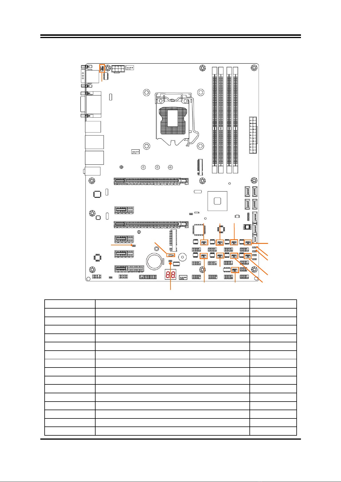
1-2 LAYOUT DIAGRAM....................................................................................................2
CHAPTER 2 HARDWARE INSTALLATION
2-1 JUMPER SETTING .....................................................................................................6
2-2 CONNECTORS AND HEADERS................................................................................11
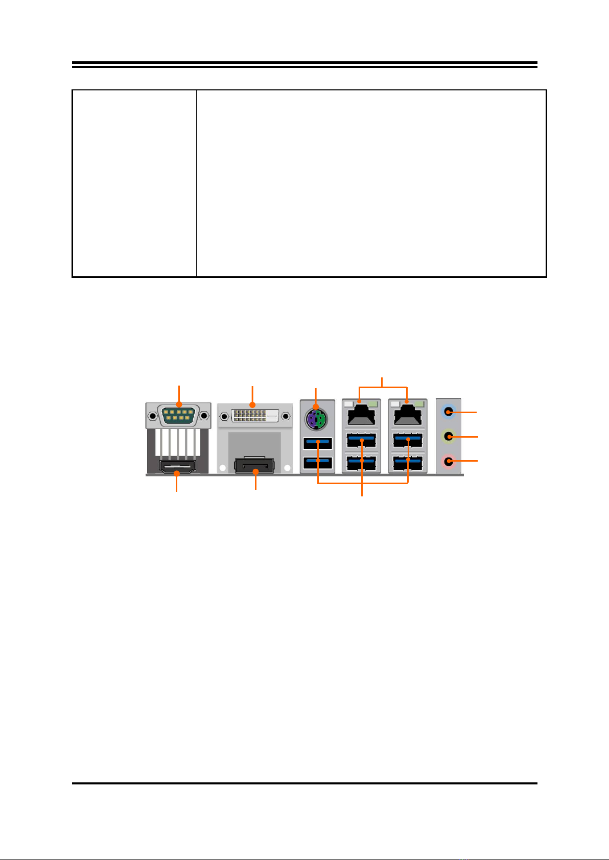
2-2-1 REAR I/O BACK PANEL CONNECTORS....................................................11
2-2-2 MOTHERBOARD INTERNAL CONNECTORS............................................12
2-2-3 HEADER PIN DEFINITION...........................................................................15
CHAPTER 3 INTRODUCING BIOS
3-1 ENTERNING SETUP...................................................................................................20
3-2 BIOS MENU SCREEN ................................................................................................20
3-3 FUNCTION KEYS .......................................................................................................21
3-4 GETTING HELP ..........................................................................................................21
3-5 MENU BARS...............................................................................................................22
3-6 MAIN MENU................................................................................................................22
3-7 ADVANCED MENU.....................................................................................................23
3-8 CHIPSET MENU..........................................................................................................31
3-9 SECURITY MENU.......................................................................................................33
3-10 BOOT MENU...............................................................................................................33
3-11 SAVE & EXIT MENU...................................................................................................34
TABLE OF CONTENT

iii
Environmental Safety Instruction
Avoid the dusty, humidity and temperature extremes. Do not place the product in
any area where it may become wet.
0 to 40 centigrade is the suitable temperature. (The figure comes from the request
of the main chipset)
Generally speaking, dramatic changes in temperature may lead to contact
malfunction and crackles due to constant thermal expansion and contraction from
the welding spots’ that connect components and PCB. Computer should go
through an adaptive phase before it boots when it is moved from a cold
environment to a warmer one to avoid condensation phenomenon. These water
drops attached on PCB or the surface of the components can bring about
phenomena as minor as computer instability resulted from corrosion and oxidation
from components and PCB or as major as short circuit that can burn the
components. Suggest starting the computer until the temperature goes up.
The increasing temperature of the capacitor may decrease the life of computer.
Using the close case may decrease the life of other device because the higher
temperature in the inner of the case.
Attention to the heat sink when you over-clocking. The higher temperature may
decrease the life of the device and burned the capacitor.
Environmental Protection Announcement
Do not dispose this electronic device into the trash while discarding. To minimize
pollution and ensure environment protection of mother earth, please recycle.

iv
USER’S NOTICE
COPYRIGHT OF THIS MANUAL BELONGS TO THE MANUFACTURER. NO PART OF THIS MANUAL,
INCLUDING THE PRODUCTS AND SOFTWARE DESCRIBED IN IT MAY BE REPRODUCED, TRANSMITTED
OR TRANSLATED INTO ANY LANGUAGE IN ANY FORM OR BY ANY MEANS WITHOUT WRITTEN
PERMISSION OF THE MANUFACTURER.
THIS MANUAL CONTAINS ALL INFORMATION REQUIRED TO USE THIS MOTHER-BOARD SERIES AND WE
DO ASSURE THIS MANUAL MEETS USER’S REQUIREMENT BUT WILL CHANGE, CORRECT ANY TIME
WITHOUT NOTICE. MANUFACTURER PROVIDES THIS MANUAL “AS IS” WITHOUT WARRANTY OF ANY
KIND, AND WILL NOT BE LIABLE FOR ANY INDIRECT, SPECIAL, INCIDENTAL OR CONSEQUENTIAL
DAMAGES (INCLUDING DAMAGES FOR LOSS OF PROFIT, LOSS OF BUSINESS, LOSS OF USE OF DATA,
INTERRUPTION OF BUSINESS AND THE LIKE).
PRODUCTS AND CORPORATE NAMES APPEARING IN THIS MANUAL MAY OR MAY NOT BE
REGISTERED TRADEMARKS OR COPYRIGHTS OF THEIR RESPECTIVE COMPANIES, AND THEY ARE
USED ONLY FOR IDENTIFICATION OR EXPLANATION AND TO THE OWNER’S BENEFIT, WITHOUT
INTENT TO INFRINGE.
Manual Revision Information
Reversion Revision History Date
4.0 Fourth Edition October 1, 2019
Item Checklist
Motherboard
Cable(s)
I/O Back panel shield

1
Chapter 1
Introduction of the Motherboard
1-1 Specification
Spec
Description
Design
ATX form factor; PCB size: 30.5 x24.5 cm
Chipset
Intel®Q170 Express Chipset
LGA1155
CPU Socket
Supports Intel
®
Core™ i7, Core™ i5, Core™ i3 series,
Pentium®processor in LAG1151 Package (Max. 65W
TDP)
* for detailed CPU support information please visit our website
Memory Slot
4*DDR4 RAM module slot
Supporting 4* 2133MHz DDR4 RAM Module, expandable
to 64 GB (Maximum)
Support dual-channel function
Expansion Slots
1 * PCI-Express x16 slot (PCIE1, share with PCIE3 slot)
1 * PCI-Express x 8 slot (PCIE3, share with PCIE1 slot)
1 * PCI-Express x4 slot (PCIE6)
3 * PCI-Express x1 slot (PCIE2/4/5)
1 * Full-size Mini-PCIE slot (MPE)
Storage
4 * SATAIII 6Gb/s port (SATA1/2/3/4)
1 * SATA Express 10Gb/s port (SE1)
Support RAID 0, 1, 5, 10 function
1* M.2 Socket 3 connector (Socket 3, M-key, support type
2242/2260/2280/22110 SATA & PCIE x4 SSD, shares
with SATA1, ME FW optional)
LAN Chip
Integrated with Intel i211AT Gigabit PCI-E LAN chip & Intel
i219-LM Gigabit LAN PHY chip
Support Fast Ethernet LAN function of providing
10/100/1000Mbps Ethernet data transfer rate
Audio Chip
Realtek ALC662 6-channel Audio Codec integrated
Audio driver and utility included
BIOS
128M Bit SMT Flash ROM
Multi I/O
Rear Panel I/O:
1*Serial port connector
1*DVI-D port connector
1* HDMI port connector
1* Display port connector
1* PS/2 keyboard & mouse combo port connector
2* RJ-45 LAN port connector
6* USB 3.0 port connector
1*3-jack audio connector (Line-in, Line-out, MIC)
Internal I/O Connectors & Headers:
1 *24-pin main power connector
1 *8-pin 12V power connector

2
1* Front panel audio header
1* HDMI-SPDIF header
1* GPIO header
1* TPM 1.2 header
2* front panel USB 2.0 header (support 4* expansion
USB
2.0 ports)
1* Front panel header
1* Speaker header+ 1* POWER LED header
1* SM_BUS header
2* LAN Status indicator header
9* COM port header (COM2/3/4/5/6/7/8/9/10, COM2
supports RS422/RS485 function )
3* FAN header
1-2 Layout Diagram
Rear IO Diagram
* Note: Many PCs now include XHCI USB controllers which allow for the support of
USB 3.0 and higher USB speeds. This inclusion of XHCI controllers has lessened the
need for EHCI USB controllers within platforms. However, legacy operating systems
(OS) may not natively recognize XHCI controllers. You might need to pre-install XHCI
driver while desiring to install a non-XHCI OS (ex.Windows* 7) on Intel platforms
which do not include EHCI controllers. Please contact your representative for more
details.
COM1
Serial Port
HDMI Port
Display Port
DVI-D Port
RJ-45 LAN Ports
PS/2 KB & MS
Combo Port
Line-OUT
MIC-IN
USB 3.0 Ports
Line-IN

3
Motherboard Internal Diagram
*Note: 1. PCIE1 slot shares function with PCIE3 slot, i.e. only one can function at a time.
2. M.2 shares function with SATA1port; user can only choose one to use at one time.
DVI-D Port over
Display Port
PS/2 KB & MS Port
over USB 3.0 Ports
Audio Connectors
LGA 1151
CPU Socket
ATX Power
Connector
SATAIII Ports
(SATA1/2/3/4)
Intel Q170
Chipset
Serial Port over
HDMI Port
RJ-45 LAN Ports
Over USB 3.0 Ports
ATX 12V
Power Connector
Front Panel
Audio Header
GPIO Header
TPM Header
SYS FAN2 Header
USB 2.0 Headers
Front Panel
Header
PWR LED &
Speaker Header
Serial Port Header
(COM2)
Full-size
Mini-PCIE Slot
(MPE) *
LANLED Headers
SMBUS Header
SATA Express
Connector
(SE1)
DDR4
DIMM Slot x 4
SYS FAN1 Header
CPUFAN Header
PCI Express 2.0 x1 Slot (PCIE2)
PCI Express x16 Slot (PCIE1)
PCI Express x8 Slot (PCIE3)
PCI Express 2.0 x1 Slot (PCIE4)
PCI Express 2.0 x1 Slot (PCIE5)
PCI Express 2.0 x4 Slot (PCIE6
)
HDMI_SPDIF
Header
M.2 Socket 3 Connector
(M1/2/3/4) *
Serial Port Headers
(COM3/4/5/6/7/8/9/10)

4
Motherboard Jumper Position
Jumper
Jumper
Name
Description
JP1
COM1 Port Pin9 Function Select
4-pin Block
JP13
COM2 Header Pin9 Function Select
4-pin Block
JP3
COM3 Header Pin9 Function Select
4-pin Block
JP4
COM5 Header Pin9 Function Select
4-pin Block
JP5
COM7 Header Pin9 Function Select
4-pin Block
JP6
COM9 Header Pin9 Function Select
4-pin Block
JP9
COM4 Header Pin9 Function Select
4-pin Block
JP10
COM6 Header Pin9 Function Select
4-pin Block
JP11
COM8 Header Pin9 Function Select
6-pin Block
JP12
COM10 Header Pin9 Function Select
6-pin Block
JP7
ME_Features Select
2-pin Block
JP8
Mini PCI-E Slot (MPE)VCC3.3V/3.3VSB Select
3-pin Block
JBAT
CMOS RAM Clear Function Setting
2-pin Block
Case_OPEN
Case Open Message Display Function Select
2-pin Block
AT_MODE
ATX/AT Mode Select
2-pin Block
CASE_OPEN
JP1
JBAT
JP13
JP3
JP10
JP9
JP4
JP6
JP7
JP8
JP5
AT_MODE
JP12
JP11

5
Connectors
Connector
Name
ATXPWR
ATX Power Connector
ATX12V
ATX 12V Power Connector
COM1
Serial Port COM Connector
HDMI
High-Definition Multimedia Interface Connector
DVI
DVI-D Port Connector
DP
Display Port Connector
PS2_USB1
Top: PS/2 Keyboard & Mouse Combo Port
Middle & Bottom: USB 3.0 Connector X2
UL1/UL2
Top:RJ-45 LAN Connector X2
Middle & Bottom: USB 3.0 Port Connector X2
AUDIO
Top: Line-in/Optical SPDIF-out Connector
Middle: Line-out Connector
Bottom: MIC Connector
SATA1/2/3/4
SATAIII Connector X4
SE1
SATA Express Port Connector
Headers
Header
Name
Description
FP_AUDIO
Front Panel Audio Header
9-pin Block
HDMI_SPDIF
HDMI_SPDIF Out Header
2-pin Block
GPIO
GPIO Header
10-pin Block
TPM
TPM Header
19-pin Block
USB2/USB3
USB 2.0 Header
9-pin Block
COM 2/3/4/5/6/7/8/9/10
Serial Port Header
9-pin Block
FP (Front Panel Header)
PWR LED/ HD LED/ Power Button
/Reset
9-pin Block
SPK_LED
Power LED & Speaker Header
7-pin Block
SM_BUS
SMBUS Header
5-pin Block
LAN1_LED1/ LAN2_LED
LANLED Activity Header
2-pin Block
SYSFAN1/SYSFAN2/CPUFAN
FAN Header
4-pin Block

6
Chapter 2
Hardware Installation
2-1 Jumper Setting
JP1 (4-pin): COM1 Port Pin9 Function Select
JP1
→
COM1 Port
6
4
2
3
1
5
1
2
4
6
3
5
2
4
6
1
3
5
2-4 Closed:
RI=RS232;
3-4 Closed:
RI= 5V;
4-6 Closed:
RI= 12V;
JP13 (4-pin): COM2 Header Pin9 Function Select
JP13
→
COM2 Header
4-6 Closed:
RI= 12V;
6
4
2
3-4 Closed:
RI= 5V;
2-4 Closed:
RI=RS232;
3
1
5
1
3
5
2
4
6
1
3
5
2
4
6
JP3 (4-pin): COM3 Header Pin9 Function Select
JP3
→
COM3 Header
4-6 Closed:
RI= 12V;
6
4
2
3-4 Closed:
RI= 5V;
2-4 Closed:
RI=RS232;
3
1
5
1
3
5
2
4
6
1
3
5
2
4
6

7
JP4 (4-pin): COM5 Header Pin9 Function Select
JP4
→
COM5Header
4-6 Closed:
RI= 12V;
6
4
2
3-4 Closed:
RI= 5V;
2-4 Closed:
RI=RS232;
3
1
5
1
3
5
2
4
6
1
3
5
2
4
6
JP5 (4-pin): COM7 Header Pin9 Function Select
JP5
→
COM7 Header
4-6 Closed:
RI= 12V;
6
4
2
3-4 Closed:
RI= 5V;
2-4 Closed:
RI=RS232;
3
1
5
1
3
5
2
4
6
1
3
5
2
4
6
JP6 (4-pin): COM9 Header Pin9 Function Select
JP6
→
COM9 Header
4-6 Closed:
RI= 12V;
6
4
2
3-4 Closed:
RI= 5V;
2-4 Closed:
RI=RS232;
3
1
5
1
3
5
2
4
6
1
3
5
2
4
6

8
JP9 (4-pin): COM4 Header Pin9 Function Select
JP9
→
COM4 Header
4-6 Closed:
RI= 12V;
6
4
2
3-4 Closed:
RI= 5V;
2-4 Closed:
RI=RS232;
3
1
5
1
3
5
2
4
6
1
3
5
2
4
6
JP10 (4-pin): COM6 Header Pin9 Function Select
JP10→COM6 Header
4-6 Closed:
RI= 12V;
6
4
2
3-4 Closed:
RI= 5V;
2-4 Closed:
RI=RS232;
3
1
5
1
3
5
2
4
6
1
3
5
2
4
6
JP11 (4-pin): COM8 Port Pin9 Function Select
JP11
→
COM8 Header
4-6 Closed:
RI= 12V;
6
4
2
3-4 Closed:
RI= 5V;
2-4 Closed:
RI=RS232;
3
1
5
1
3
5
2
4
6
1
3
5
2
4
6

9
JP12 (4-pin): COM10 Port Pin9 Function Select
JP12→COM10 Header
4-6 Closed:
RI= 12V;
6
4
2
3-4 Closed:
RI= 5V;
2-4 Closed:
RI=RS232;
3
1
5
1
3
5
2
4
6
1
3
5
2
4
6
JP7 (2-pin): ME Features Select
1-2 Closed:ME Features Disabled.
JP7
→
ME Features
1
2
1-2 Open:ME Features Enabled;
1
2
JP8 (3-pin): Mini PCI-E (MPE) Slot VCC 3.3V/3.3 VSB Select
2-3 Closed:MINI PCI-E VCC= 3.3VSB.
JP8
→
MPE Slot
1-2 Closed:MINI PCI-E VCC= 3.3V;
1
3
1
3

10
JBAT (2-pin): Clear CMOS Function Settings
1-2 Closed: Clear CMOS.
JBAT
→
Clear CMOS
1-2 Open: Normal;
Pin1
Pin1
CASE_ OPEN (2-pin): Case Open Message Display Function Select
1-2 Closed: Case Open Function Selected.
CASE_OPEN
→
Case Open Detection
1-2 Open: Normal;
Pin1
Pin1
Pin 1-2 Closed:Case open display function enabled. Use needs to enter BIOS and
enable ‘Case Open Detect’function. In this case if you case is removed, next time
when you restart your computer a message will be displayed onscreen to inform you
of this.
AT_MODE (2-pin): AT Mode Function Select
1-2 Closed: AT Mode Selected.
AT_MODE
→
AT/ATX Mode Select
1-2 Open: ATX Mode Selected;
Pin1
Pin1
*ATX Mode Selected: Press power button to power on after power input ready;

11
AT Mode Selected: Directly power on as power input ready.
2-2 Connectors and Headers
2-2-1 Rear I/O Back Panel Connectors
*Refer to Page-2.
Icon Name Function
RS232/422/485
Serial Port
Mainly for user to connect external MODEM or
other devices that supports
Serial Communications Interface.
DVI-D Port To connect display device that support DVI
specification
(Max. resolution Support:1920*1080@60Hz).
HDMI Port To connect display device that support HDMI
specification.
(Max. resolution Support: 4096*2160@60Hz)
Display Port To the system to corresponding display device
with compatible DP cable.
(Max. resolution Support : 4096*2304@60Hz)
PS/2 Mouse
& Keyboard
Combo Port
This combo port is for user to connect PS/2
mouse
or keyboard device to the board.
USB 3.0 Port To connect USB keyboard, mouse or other
devices compatible with USB specification. USB
3.0 ports supports up to 5Gbps data transfer rate.
RJ-45 LAN Port This connector is standard RJ-45 LAN jack for
Network connection.
Audio Connectors
BLUE: Line-in Connector
GREEN:Line-out Connector
PINK : MIC Connector
COM1 (9-pin Block): RS232/422/485 Port
COM1 port can function as RS232/422/485 port. In normal settings COM1 functions
as RS232 port. With compatible COM cable COM1 can function as RS422 or RS 485
port.
User also needs to go to BIOS to set ‘Transmission Mode Select’for COM1 (refer to
Page 24)at first, before using specialized cable to connect different pins of this port.

12
2-2-2 Motherboard Internal Connectors
(1) ATXPWR (24-pin block): Main Power Connector
ATX Power Supply connector: This is a new defined 24-pins connector that
usually comes with ATX case. The ATX Power Supply allows using soft power
on momentary switch that connect from the front panel switch to 2-pins Power
On jumper pole on the motherboard. When the power switch on the back of the
ATX power supply turned on, the full power will not come into the system board
until the front panel switch is momentarily pressed. Press this switch again will
turn off the power to the system board.
** We recommend that you use an ATX 12V Specification 2.0-compliant power
supply unit (PSU) with a minimum of 350W power rating. This type has 24-pin
and 4-pin power plugs.
** If you intend to use a PSU with 20-pin and 4-pin power plugs, make sure that the
20-pin power plug can provide at least 15A on +12V and the power supply unit
has a minimum power rating of 350W. The system may become unstable or may
not boot up if the power is inadequate.
** If you are using a 20-pin power plug, please refer to Figure1 for power supply
connection. Power plug form power supply and power connectors from
motherboard both adopt key design to avoid mistake installation. You can insert
the power plug into the connector with ease only in the right direction. If the
direction is wrong it is hard to fit in and if you make the connection by force if is
possible.
Figure1:20-pin power plug Figure 2:24-pin power plug

13
(2) ATX12V (8-pin block): 12V Power Connector
This is a new defined 8-pin connector that usually comes with ATX Power Supply that
supports extra 12V voltage to maintain system power consumption. Without this
connector might cause system unstable because the power supply can not provide
sufficient current for system.
(3) SATA1/2/3/4: SATAIII Port Connector
These connectors are high-speed SATAIII ports that support 6 GB/s transfer rate.
Pin No.
Definition
1
GND
2
TXP
3
TXN
4
GND
5
RXN
6
RXP
7
GND
(4) SE1: SATA Express Port Connector
This SATA Express port connector can support one single SATA Express device that
support 10 GB/s transfer rate.

14
* Note: Port A& Bcan function as SATA III 6Gb/s port as well when not connected with a SATA
Express device.
(5) M2: M2 Socket 3 Connector
This M2 Socket 3 connector support compatible type 2242/2260/2280/22110 SATA &
PCIE x4 SSD module.
M.2 Module Installation Guide
1. Prepare compatible M.2 SATA or M.2 SSD card. Deferent type of cards has different
length. Find corresponding nut location for further installation.
Nut Location
MH1
MH2
MH3
MH4
Card Length
4.2 cm
6 cm
8 cm
11 cm
Module Type
Type 2242
Type 2260
Type 2280
Type 22110
2. Remove the screw post and nut fixed at
location MH4 by default (Skip step 2 & 3
and go straight to Step 4 if you are going
to use the default nut).
3. Lock the screw post into the location
corresponding to the length of the
module.
4. Align and insert corresponding M.2
module, as the photo shows.
5. Tighten up the screw to secure the
module into the M.2 connector. Mare
sure not overtighten the screw to avoid
possible damage to the module.

15
2-2-3 Header Pin Definition
(1) FP_AUDIO (9-pin): Line-Out, MIC-In Header
This header is connected to Front Panel Line-out, MIC connector with cable.
Pin 1
MIC1-R
LINE OUT-L
MIC1-L
LINE OUT-R
NC
GND
NC
NC
NC
2
(2) HDMI_SPDIF (2-pin): HDMI-SPDIF Out header
Pin1
SPDIF
GND
(3) GPIO (10-pin): GPIO Header
9
GPIO
GND
GPIO
GPIO
GPIO
GPIO
GPIO
2
Pin 1
10
VCC
GPIO
GPIO

16
(4) TPM (19-pin): TPM Header
CLK
VCC3.3V
LFRAME-
RESET
LAD3
GND
VCC5V
KEY/NC
2
Pin 1
LAD2
LAD1
LAD0
SMB_CLK
SB 3.3V
GND
GND
SMB_DATA
SERIRQ
NC/GND
GPIO
LPC_PD-
(5) USB 2.0 Port Headers (9-pin): USB3/USB4
Pin 1
VCC
-DATA
GND
+DATA
VCC
NC
-DATA
GND
+DATA
2
(6) FP (9-pin): Front Panel Header
HDLED
RESET
HDDLED+
GND
PWRLED+
PWRBTN
GND
PWRLED-
HDDLED-
RSTSW
VCC
PWRBT
Pin 1
2
PWR LED
Table of contents
Other JETWAY Motherboard manuals

JETWAY
JETWAY NF9M User manual

JETWAY
JETWAY MBD-J-JNF9KC-1047 User manual

JETWAY
JETWAY J-630AF User manual

JETWAY
JETWAY I401R5A User manual

JETWAY
JETWAY NF18GFR3A User manual

JETWAY
JETWAY 993BSR4A User manual

JETWAY
JETWAY M26GT4SVM User manual

JETWAY
JETWAY NF9A-Q67 User manual

JETWAY
JETWAY 845CAR1A User manual

JETWAY
JETWAY 915GDBR3A User manual

JETWAY
JETWAY NF731V Series User manual

JETWAY
JETWAY 531CF-6 User manual

JETWAY
JETWAY 740DMR1A User manual

JETWAY
JETWAY PM9M - REV 2.0 User manual

JETWAY
JETWAY PT800DB - REV 1.0 User manual

JETWAY
JETWAY 867ASR2A User manual

JETWAY
JETWAY 754TURBOR208 User manual

JETWAY
JETWAY NF894 Series User manual

JETWAY
JETWAY MU03 Series User manual

JETWAY
JETWAY 601CFR4A User manual