JETWAY K8M8MSR1A User manual

K8M8MS/K8M8M
USER'S MANUAL
M/B For Socket 754 AMD Athlon64
Processor
NO. G03-K8M8MS
Rev:1.0
Release date: October 2004
Trademark:
* Specifications and Information contained in this documentation are furnished for information use only, and are
subject to change at any time without notice, and should not be construed as a commitment by manufacturer.

i
USER’S NOTICE.....................................................................................................................ii
MANUAL REVISION INFORMATION ..............................................................................ii
COOLING SOLUTIONS........................................................................................................ii
CHAPTER 1 INTRODUCTION OF K8M8MS/K8M8M MOTHERBOARD
1-1 FEATURE OF MOTHERBOARD ...................................................................................... 1
1-2 SPECIFICATION.................................................................................................................. 2
1-3 PERFORMANCE LIST........................................................................................................ 3
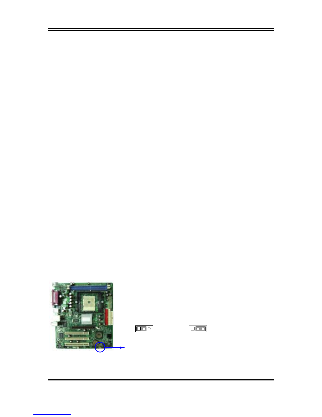
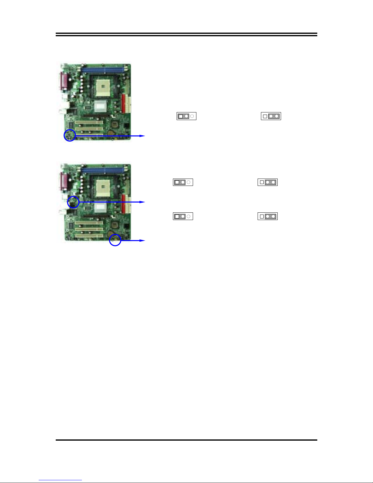
1-4 LAYOUT DIAGRAM & JUMPER SETTING ................................................................... 4
CHAPTER 2 HARDWARE INSTALLATION
2-1 HARDWARE INSTALLATION STEPS............................................................................. 6
2-2 CHECKING MOTHERBOARD'S JUMPER SETTING................................................... 6
2-3 INSTALL CPU....................................................................................................................... 7
2-3-1 GLOSSARY................................................................................................................ 7
2-3-2 ABOUT INTEL AMD K8 754-PIN CPU ............................................................. 8
2-4 INSTALL MEMORY............................................................................................................ 9
2-5 EXPANSION CARD.............................................................................................................. 10
2-5-1 PROCEDURE FOR EXPANSION CARD INSTALLATION ............................... 10
2-5-2 ASSIGNING IRQ FOR EXPANSION CARD......................................................... 10
2-5-3 INTERRUPT REQUEST TABLE FOR THIS MOTHERBOARD....................... 11
2-5-4 AGP SLOT.................................................................................................................. 11
2-6 CONNECTORS, HEADERS ................................................................................................ 12
2-6-1 CONNECTORS.......................................................................................................... 12
2-6-2 HEADERS .................................................................................................................. 15
2-7 STARTING UP YOUR COMPUTER.................................................................................. 17
CHAPTER 3 INTRODUCING BIOS
3-1 ENTERING SETUP............................................................................................................... 18
3-2 GETTING HELP ................................................................................................................... 18
3-3 THE MAIN MENU................................................................................................................ 19
3-4 STANDARD CMOS FEATURES ........................................................................................ 20
3-5 ADVANCED BIOS FEATURES .......................................................................................... 21
3-6 ADVANCED CHIPSET FEATURES .................................................................................. 23
3-6-1 DRAM TIMING SETTINGS.................................................................................... 24
3-6-2 AGP FUNCTION SETTINGS .................................................................................. 25
3-6-3 PCI TIMING SETTINGS ......................................................................................... 25
3-7 INTEGRATED PERIPHERALS.......................................................................................... 26
3-7-1 ONCHIP IDE FUNCTION ....................................................................................... 26
3-7-2 ONCHIP DEVICE FUNCTION ............................................................................... 27
3-7-3 ONCHIP SUPER IO FUNCTION............................................................................ 28
3-8 POWER MANAGEMENT SETUP...................................................................................... 29
3-8-1 PM WAKE UP EVENTS.......................................................................................... 30
3-8-1.1 IRQS ACTIVITIES................................................................................................. 31
3-9 PNP/PCI CONFIGURATION SETUP ................................................................................ 31
3-9-1 IRQ RESOURCES .................................................................................................... 32
3-10 PC HEALTH STATUS ........................................................................................................ 33
3-11 MISCELLANEOUS CONTROL ........................................................................................ 34
3-12 LOAD STANDARD/OPTIMIZED DEFAULTS ............................................................... 35
3-13 SET SUPERVISOR/USER PASSWORD........................................................................... 35
CHAPTER 4 DRIVER & FREE PROGRAM INSTALLATION
MAGIC INSTALL SUPPORTS WINDOWS 9X/ME/NT4.0/2000/XP........................................ 36
4-1 VIA 4 IN 1 INSTALL VIA SERVICE PACK 4 IN 1 DRIVER............................... 37
4-2 VGA INSTALL VIA K8M800 VGA DRIVER ............................................... 38
4-3 SOUND INSTALL AC97 AUDIO CODEC DRIVER ......................................... 39
4-4 LAN INSTALL VIA 10/100MB LAN CONTROLLER DRIVER ................ 40
4-5 USB2.0 INSTALL VIA USB2.0 DEVICE DRIVER ........................................... 40
4-6 SATA INSTALL VIA SERIAL ATA DRIVER ............................................... 41
4-7 PC-CILLIN INSTALL PC-CILLIN2004 ANTI-VIRUS PROGRAM...................... 43
4-8 HOW TO DISABLE ON-BOARD SOUND......................................................................... 44
4-9 HOW TO UPDATE BIOS..................................................................................................... 44
TABLE OF CONTENT

ii
USER’S NOTICE
COPYRIGHT OF THIS MANUAL BELONGS TO THE MANUFACTURER. NO PART OF THIS
MANUAL, INCLUDING THE PRODUCTS AND SOFTWARE DESCRIBED IN IT MAY BE
REPRODUCED, TRANSMITTED OR TRANSLATED INTO ANY LANGUAGE IN ANY FORM OR
BY ANY MEANS WITHOUT WRITTEN PERMISSION OF THE MANUFACTURER.
THIS MANUAL CONTAINS ALL INFORMATION REQUIRED TO USE K8M8MS/K8M8M
MOTHER-BOARD AND WE DO ASSURE THIS MANUAL MEETS USER’S REQUIREMENT BUT
WILL CHANGE, CORRECT ANY TIME WITHOUT NOTICE. MANUFACTURER PROVIDES THIS
MANUAL “AS IS” WITHOUT WARRANTY OF ANY KIND, AND WILL NOT BE LIABLE FOR ANY
INDIRECT, SPECIAL, INCIDENTIAL OR CONSEQUENTIAL DAMAGES (INCLUDING
DAMANGES FOR LOSS OF PROFIT, LOSS OF BUSINESS, LOSS OF USE OF DATA,
INTERRUPTION OF BUSINESS AND THE LIKE).
PRODUCTS AND CORPORATE NAMES APPEARING IN THIS MANUAL MAY OR MAY NOT BE
REGISTERED TRADEMARKS OR COPYRIGHTS OF THEIR RESPECTIVE COMPANIES, AND
THEY ARE USED ONLY FOR IDENTIFICATION OR EXPLANATION AND TO THE OWNER’S
BENEFIT, WITHOUT INTENT TO INFRINGE.
Manual Revision Information
Reversion Revision History Date
1.0 First Edition October 2004
Item Checklist
5K8M8MS/K8M8M motherboard
5Cable for IDE/Floppy
5CD for motherboard utilities
□Cable for USB Port 3/4 (Option)
5Cable for Serial ATA IDE Port
5K8M8MS/K8M8M User’s Manual
AMD K8 Processor Family
Cooling Solutions
As processor technology pushes to faster speeds and higher performance with increasing operation
clock, thermal management becomes increasingly crucial while building computer systems. Maintaining
the proper computing environment without thermal increasing is the key to reliable, stable, and 24
hours system operation. The overall goal is keeping the processor below its specified maximum case
temperature. Heatsinks induce improved processor heat dissipation through increasing surface area
and concentrated airflow from attached active cooling fans. In addition, interface materials allow
effective transfers of heat from the processor to the heatsink. For optimum heat transfer, AMD
recommends the use of thermal grease and mounting clips to attach the heatsink to the processor.
Please refer to the website below for collection of heatsinks evaluated and recommended for Socket-A
processors by AMD. In addition, this collection is not intended to be a comprehensive listing of all
heatsinks that support Socket-754 processors.
For vendor list of heatsinks and Active cooling fans, please visit:
http://www.amd.com/us-en/Processors/DevelopWithAMD/0,,30_2252_869_9460^9515,00.html

1
Chapter 1
Introduction of K8M8MS/K8M8M Motherboard
1-1 Feature of motherboard
The K8M8MS/K8M8M motherboard is design for use 64bit AMD Athlon64 (K8) Processor
in 754 Pin HyperTrnsport Processor with the VIA K8M800 Chipset delivers a high performance
and professional desktop platform solution. Which utilize the Socket 754 design and the
memory size expandable to 2.0GB.
These motherboards use the newest VIA K8M800 Chipset, supports 800MHz System Bus in
data transfer rate. These motherboards provided 133MHz/166MHz/ 200MHz Memory clock
frequency, support DDR266/DDR333/DDR400 DDR Module. The motherboard embedded
VIA VT8237 V-Link LPC South Bridge offer ULTRA ATA 133 and Serial ATA RAID 0, 1
functions to provide speedier HDD throughout that boosts overall system performance. The
K8M8MS used the RealTek RT8100C LAN controller chip supports 10/100Mbps data
transfer rate full duplex, half duplex operation.
These motherboards also has an integrated 6-channel AC’97 CODEC on board which is fully
compatible with Sound Blaster Prothat gives you the best sound quality and compatibility.
K8M8MS/K8M8M motherboards integrated High Performance & High Quality 3D
Accelerator supports Ultra-AGPII with 2GB/s bandwidth, built-in MPEG-2/1 Video Decoder
and Video Accelerator supports VCD DVD HDTV decoding and playback, supports graphic
and video overlay function. Built-in programmable 24-bit true-color RAMDAC up to
300MHz pixel clock. Programmable frame buffer size from 16MB and up to 64MB. For those
wanting even greater graphic performance. K8M8MS/K8M8M provided an AGP slot supports
AGP 8X/4X capability and Fast write Transaction.
With USB control as well as capability of expanding to 8x USB2.0 function ports delivering
480Mb/s bandwidth and rich connectivity, these motherboards meet future USB demand also
has built-in hardware monitor function to monitor and protect your computer.
A useful software tool “Magic BIOS” examines the BIOS version automatically with the
correct version available on the web, links the site for users to download the latest version of
BIOS and updates the BIOS. Use “Magic BIOS”, users can download and update BIOS
automatically and completed under the OS easily.
These motherboards provide high performance & meets future specification demand. It is
really wise choice for your computer.

2
1-2 Specification
Spec Description
Design ∗Micro ATX form factor 4 layers PCB size: 24.4x21.0cm
Chipset ∗VIA K8M800 North Bridge Chipset
∗VIA VT8237 South Bridge Chipset
CPU Socket
(mPGA754 Socket)
∗Support 64bit AMD Athlon64 754-Pin package utilizes Flip-
Chip Pin Grid Array package processor
∗Support CPU Frequency 800MHz
∗Support up to 3200+, 3400+ processor
∗Reserves support for future AMD Athlon64 754-pin processors
Memory Socket ∗184-pin DDR Module socket x 2
∗Support 2pcs DDR266/DDR33/DDR400 DDR Modules
Expandable to 2.0GB
Expansion Slot ∗AGP slot x1 support AGP 2.0 & AGP 3.0 for 4X/8X mode
∗32-bit PCI slot x3
Integrate IDE and
Serial ATA RAID
∗Two PCI IDE controllers support PCI Bus Mastering, ATA
PIO/DMA and the ULTRA DMA 33/66/100/133 functions that
deliver the data transfer rate up to 133 MB/s; Two Serial ATA
ports provide 150 MB/sec data transfer rate for two Serial ATA
Devices and offer RAID 0, 1 functions
VGA
∗Integrated High Performance & High Quality 3D Accelerator
∗Support Ultra-AGPII with 2GB/s bandwidth
∗Built-in programmable 24-bit true-color RAMDAC up to
300MHz pixel clock
∗Programmable frame buffer size from 16MB and up to 64MB.
LAN
( for K8M8MS)
∗Integrated RealTek RT8100C PCI LAN chip
∗Support Fast Ethernet LAN function provide 10/100 Mb/s data
transfer rate
Audio ∗AC’97 Digital Audio controller integrated
∗6-channel AC’97 Audio CODEC on board
∗Audio driver and utility included
BIOS ∗Award 2MB Flash ROM
Multi I/O ∗PS/2 keyboard and PS/2 mouse connectors
∗Floppy disk drive connector x1
∗Parallel port x1
∗Serial port x1
∗USB2.0 port x 4 and headers x 4 (connecting cable option)
∗Audio connector (Line-in, Line-out, MIC)

3
1-3 Performance List
The following performance data list is the testing result of some popular benchmark
testing programs. These data are just referred by users, and there is no responsibility
for different testing data values gotten by users (the different Hardware & Software
configuration will result in different benchmark testing results.)
Performance Test Report
CPU: AMD K8 ATHLON 64 3400+ Support
DRAM: TwinMOS Hynix HY5DU56822CT 512MB DDR400 X 2 (1Gbyte) Memory
On Board VGA : Onboard VGA share 64M (1024X768X32BIT Color)
Hard Disk Driver: IBM IC35L040AVVN07-0 (ATA-100 7200RPM)
BIOS: Award Optimal default
OS: Windows XP Professional (SERVICE PACK 2)
K8M8MS 200/200
3D Mark 2001SE 2069
3D Mark 2003 117
3D Mark 2005 N/A
AQUAMRK3 5174
PCMark2004
System / CPU / Memory 3282 / 4126 / 3574
Graph / HDD 638 / 4571
Content Creation Winstone 2004 33.3
Business Winstone 2004 25.4
Winbench 99 V2.0:
Business/Hi-end Disk Winmark99 13500 / 34700
Business/Hi-end Graphic Winmark 381 / 1550
SISMark 2004: SISMark Rating(Internet Content Creation / Office
Productivity )
SISMark 2004 175 (194 / 158)
3D Creation / 2D Creation 185 / 233
/ Web publication 169
Communication / Document Creation 139 / 187
/ Data Analysis 152
SISOFT Sandra 2004 : 1.CPU Arithmetic Benchmark 2.Memory
bandwidth Benchmark 3.CPU Multi-Media Benchmark
1.Dhrystone ALU MIPS 9185
Whetstone FPU iSSE2 MFLOPS 3468 / 4532
2.Int/Float Buffered iSSE2 MB/S 2786 / 2786
3.Integer/Floating-Point SSE2 IT/S 10409 / 21668
UT2003 Benchmark (flyby/botmatch) 269.68 / 95.36
Quake3 DEMO1 / DEMO2 FPS 67.6 / 68.0
Return to Castle Wolfenstein FPS 59.7
Super Pi (1M) Second 41s
CPUZ System / CPU Clock 200.0 / 2199.9

4
1-4 Layout Diagram & Jumper Setting
LINE-OUT
LINE-IN
COM1 VGA
USB1
MIC
PS/2 Mouse
PS/2 Keyboard
USB
PRINT
(for K8M8MS)
LAN
PC99 Back Panel
PS2 KB/Mouse Port
USB Port
(USB2, USB3)
2MBit Flash ROM BIOS
SFAN1
Floppy Connector
Front Panel Connector
ATA 133 IDE Connector
(IDE1, IDE2)
Clear CMOS (JBAT)
VIA VT8237 Chip
Speaker/Power LED Connector
AGP Slot
VIA K8M800 Chipset
CPU FAN
CPU Socket
DDR Socket X2
USB Port/ LAN Connector
ATX Power Connector
USB Port
Audio Connector
KBMS/USB Power On Jumper
(JP1)
Serial-ATA Connector
(SATA1, 2)
USB Power On Jumper (JP3)
Front Panel Audio
CD Audio In
RealTek RTL8100C LAN Chip
PCI Slot
6-CH AC’97 Audio Codec
SFAN2
FINTEK F71805F LPC I/O chip
LAN function Jumper (JP2)
ATX 12V Power Connector

5
Jumpers
Jumper Name Description Page
JBAT CMOS RAM Clear 3-pin Block P.6
JP1 Keyboard/USB Power On
Enabled/Disabled
3-pin Block P.7
JP2 On board LAN Enabled/Disabled 3-pin Block P.7
JP3 USB Power On Enabled/Disabled 3-pin Block P.7
Connectors
Connector Name Description Page
ATXPWR ATX Power Connector 20-pin Block P.12
ATX12V ATX 12V Power Connector 4-pin Block P.12
PS2KBMS PS/2 Mouse & PS/2 Keyboard
Connector
6-pin Female P.12
USB/USB1 USB Port Connector 4-pin Connector P.12
LAN LAN Port Connector RJ-45 Connector P.12
PARALLEL Parallel Port Connector 25-pin Female P.13
CN1 Audio Connector 3 phone jack Connector P.13
COM1 Serial Port COM1 Connector 9-pin Connector P.13
VGA VGA Connector 15-pin Female P.13
FDD Floppy Driver Connector 34-pin Block P.13
IDE1/IDE2 Primary/Secondary IDE Connector 40-pin Block P.13
SATA1/SATA2 Serial ATA IDE Connector 7-pin Connector P.14
for K8M8MS Only
Headers
Header Name Description Page
AUDIO SPEAKER, MIC header 9-pin Block P.15
USB2, USB3 USB Port Headers 9-pin Block P.15
RESET Reset switch lead 2-pin Block P.15
SPEAK PC Speaker connector 4-pin Block P.15
HD LED IDE activity LED 2-pin Block P.15
PWR LED Power LED 2-pin Block P.15
PWR BTN Power switch 2-pin Block P.16
SFAN1, SFAN2
CPUFAN
FAN Headers 3-pin Block P.16
CDIN CD Audio-In Headers 4-pin Block P.16
Expansion Sockets
Socket/Slot Name Description Page
ZIF Socket 754 CPU Socket 754-pin mPGAB Athlon64 CPU
Socket
P.8
DIMM1, DIMM2 DDR Module Socket 184-pin DDR Module Socket P.9
PCI1, PCI2, PCI3 PCI Slot 32-bit PCI Local Bus Expansion slots P.10
AGP AGP 4X/8X Mode Slot AGP Expansion Slot P.11

6
Chapter 2
Hardware installation
2-1 Hardware installation Steps
Before using your computer, you had better complete the following steps:
1. Check motherboard jumper setting
2. Install CPU and Fan
3. Install System Memory (DIMM)
4. Install Expansion cards
5. Connect IDE and Floppy cables, Front Panel /Back Panel cable
6. Connect ATX Power cable
7. Power-On and Load Standard Default
8. Reboot
9. Install Operating System
10. Install Driver and Utility
2-2 Checking Motherboard’s Jumper Setting
(1) CMOS RAM Clear (3-pin) : JBAT
A battery must be used to retain the motherboard configuration in CMOS RAM short 1-2
pins of JBAT to store the CMOS data.
To clear the CMOS, follow the procedure below:
1. Turn off the system and unplug the AC power
2. Remove ATX power cable from ATX power connector
3. Locate JBAT and short pins 2-3 for a few seconds
4. Return JBAT to its normal setting by shorting pins 1-2
5. Connect ATX power cable back to ATX power connector
Note: When should clear CMOS
1. Troubleshooting
2. Forget password
3. After over clocking system boot fail
CMOS RAM Clear Setting
2-3 closed Clear CMOS
JBAT
13
JBAT
13
1-2 closed Normal

7
(2) On Board LAN function Enabled/Disabled: JP2
On Board LAN Setting
2-3 closed On Board LAN Disabled
JP2
1 3
JP2
13
1-2 closed On Board LAN Enabled
(Default)
(3) Keyboard/USB Power On function Enabled/Disabled: JP1, JP3
Keyboard/USB Power On Setting
2-3 closed KB/USB Power ON Enabled
JP1
1 3
JP1
13
1-2 closed KB/USB Power ON Disable
(Default)
USB2/USB3 Power On Setting
2-3 closed USB Power On Enabled
JP3
1 3
JP3
13
1-2 closed USB Power On Disable
(Default)
2-3 Install CPU
2-3-1 Glossary
Chipset (or core logic) - two or more integrated circuits which control the interfaces between
the system processor, RAM, I/O devises, and adapter cards.
Processor slot/socket - the slot or socket used to mount the system processor on the
motherboard.
Slot (AGP, PCI, ISA, RAM) - the slots used to mount adapter cards and system RAM.
AGP - Accelerated Graphics Port - a high speed interface for video cards; runs at 1X
(66MHz), 2X (133MHz), or 4X (266MHz), or 8X (533MHz).
PCI - Peripheral Component Interconnect - a high speed interface for video cards, sound
cards, network interface cards, and modems; runs at 33MHz.
ISA - Industry Standard Architecture - a relatively low speed interface primarily used for
sound cards and modems; runs at approx. 8MHz.
Serial Port - a low speed interface typically used for mouse and external modems.
Parallel Port - a low speed interface typically used for printers.
PS/2 - a low speed interface used for mouse and keyboards.
USB - Universal Serial Bus - a medium speed interface typically used for mouse, keyboards,
scanners, and some digital cameras.

8
Sound (interface) - the interface between the sound card or integrated sound connectors and
speakers, MIC, game controllers, and MIDI sound devices.
LAN (interface) - Local Area Network - the interface to your local area network.
BIOS (Basic Input/Output System) - the program logic used to boot up a computer and
establish the relationship between the various components.
Driver - software, which defines the characteristics of a device for use by another device or
other software.
Processor - the "central processing unit" (CPU); the principal integrated circuit used for doing
the "computing" in "personal computer"
Front Side Bus Frequency - the working frequency of the motherboard, which is generated
by the clock generator for CPU, DRAM and PCI BUS.
CPU L2 Cache - the flash memory inside the CPU, normal it depend on CPU type.
2-3-2 About AMD Athlon64 754-pin CPU
This motherboard provides a 754-pin surface mount, Zero Insertion Force (ZIF) socket,
referred to as the mPGA754 socket supports AMD Athlon64 processor in the 754 Pin package
utilizes Flip-Chip Pin Grid Array package technology.
The CPU that comes with the motherboard should have a cooling FAN attached to prevent
overheating. If this is not the case, then purchase a correct cooling FAN before you turn on
your system.
WARNING! Be sure that there is sufficient air circulation across the processor’s
heatsink and CPU cooling FAN is working correctly, otherwise it may
cause the processor and motherboard overheat and damage, you may install
an auxiliary cooling FAN, if necessary.
To install a CPU, first turn off your system and remove its cover. Locate the ZIF socket and
open it by first pulling the level sideways away from the socket then upward to a 90-degree
angle. Insert the CPU with the correct orientation as shown below. The notched corner
should point toward the end of the level. Because the CPU has a corner pin for two of the
four corners, the CPU will only fit in the orientation as shown.
CPU ZIF mPGAB Socket
Colden Arrow
Socket 754
When you put the CPU into the ZIF socket. No force require to insert of the CPU, then press
the level to Locate position slightly without any extra force.

9
2-4 Install Memory
This motherboard provides two 184-pin DDR DUAL INLINE MEMORY MODULES
(DIMM) sites for DDR memory expansion available from minimum memory size of 64MB to
maximum memory size of 2.0GB DDR SDRAM.
Valid Memory Configurations
Bank 184-pin DDR DIMM PCS Total Memory
Bank 0, 1 (DIMM1) DDR266/DDR333/DDR400 DDR DRAM
Module
X1 64MB∼1.0GB
Bank 2, 3 (DIMM) DDR266/DDR333/DDR400 DDR DRAM
Module
X1 64MB∼1.0GB
Total System Memory (Max. 2.0GB) X2 64MB∼2.0GB
Generally, installing DDR SDRAM modules to your motherboard is very easy, you can refer
to figure 2-4 to see what a 184-pin DDR SDRAM module looks like.
DIMM1 (BANK0+BANK1)
DIMM2 (BANK2+BANK3)
NOTE! When you install DIMM module fully into the DIMM socket the eject tab
should be locked into the DIMM module very firmly and fit into its
indention on both sides.
WARNING! For the DDR SDRAM CLOCK is set at 200MHz, use only DDR400- compliant
DDR Modules. When this motherboard operate at 200Mhz, most system will
not even boot if non-compliant modules are used because of the strict
timing issues, if your DDR Modules are not DDR400-compliant, set the
SDRAM clock to 133MHz to ensure system stability.
Figure 2-4

10
2-5 Expansion Cards
WARNING! Turn off your power when adding or removing expansion cards or other
system components. Failure to do so may cause severe damage to both
your motherboard and expansion cards.
2-5-1 Procedure For Expansion Card Installation
1. Read the documentation for your expansion card and make any necessary hardware or
software setting for your expansion card such as jumpers.
2. Remove your computer’s cover and the bracket plate on the slot you intend to use.
3. Align the card’s connectors and press firmly.
4. Secure the card on the slot with the screen you remove above.
5. Replace the computer system’s cover.
6. Set up the BIOS if necessary.
7. Install the necessary software driver for your expansion card.
2-5-2 Assigning IRQs For Expansion Card
Some expansion cards need an IRQ to operate. Generally, an IRQ must exclusively assign to
one use. In a standard design, there are 16 IRQs available but most of them are already in use.
Standard Interrupt Assignments
IRQ Priority Standard function
0 N/A System Timer
1 N/A Keyboard Controller
2 N/A Programmable Interrupt
3 * 8 Communications Port (COM2)
4 * 9 Communications Port (COM1)
5 * 6 Sound Card (sometimes LPT2)
6 * 11 Floppy Disk Controller
7 * 7 Printer Port (LPT1)
8 N/A System CMOS/Real Time Clock
9 * 10 ACPI Mode when enabled
10 * 3 IRQ Holder for PCI Steering
11 * 2 IRQ Holder for PCI Steering
12 * 4 PS/2 Compatible Mouse Port
13 N/A Numeric Data Processor
14 * 5 Primary IDE Channel
15 * 1 Secondary IDE Channel
* These IRQs are usually available for ISA or PCI devices.

11
2-5-3 Interrupt Request Table For This Motherboard
Interrupt request are shared as shown the table below:
INT A INT B INT C INT D INT E INT F INT G INT H
Slot 1 √
Slot 2 √
Slot 3
√
Onboard USB 1
√
Onboard USB 2 √
AC97/MC97
√
IMPORTANT! If using PCI cards on shared slots, make sure that the drivers support
“Shared IRQ” or that the cards don’t need IRQ assignments. Conflicts will
arise between the two PCI groups that will make the system unstable or
cards inoperable.
2-5-4 AGP Slot
This motherboard provides an AGP Slot, support the 8X/4X AGP VGA card.
2x notch 4x notch
AGP SLOT

12
2-6 Connectors, Headers
2-6-1 Connectors
(1) Power Connector (20-pin block) : ATXPWR
ATX Power Supply connector. This is a new defined 20-pins connector that usually
comes with ATX case. The ATX Power Supply allows to use soft power on momentary
switch that connect from the front panel switch to 2-pins Power On jumper pole on the
motherboard. When the power switch on the back of the ATX power supply turned on,
the full power will not come into the system board until the front panel switch is
momentarily pressed. Press this switch again will turn off the power to the system
board.
PIN ROW1 ROW2
1 3.3V 3.3V
2 3.3V -12V
3 GND GND
4 5V Soft Power On
5 GND GND
6 5V GND
7 GND GND
8 Power OK -5V
9 +5V (for Soft Logic) +5V
10 +12V +5V
(2) ATX 12V Power Connector (4-pin block) : ATX12V
This is a new defined 4-pins connector that usually comes with ATX Power Supply. The
ATX Power Supply which fully support Pentium 4 processor must including this
connector for support extra 12V voltage to maintain system power consumption.
Without this connector might cause system unstable because the power supply can not
provide sufficient current for system.
(3) PS/2 Mouse & PS/2 Keyboard Connector: PS2KBMS
The connectors for PS/2 keyboard and PS/2 Mouse.
(4) USB Port connector: USB
The connectors are 4-pin connector that connect USB devices to the system board.
(5) LAN Port connector: LAN (only for K8M8MS)
This connector is standard RJ45 connector for Network
Pin 1
Pin 1

13
(6) Parallel Port Connector (25-pin female): PARALLEL
Parallel Port connector is a 25-pin D-Subminiature Receptacle connector. The On-
board Parallel Port can be disabled through the BIOS SETUP. Please refer to Chapter 3
“INTEGRATED PERIPHERALS SETUP” section for more detail information.
(7) Audio and Game Connector : AUDIO (LINE-OUT/ LINE_IN/MIC)
This Connector are 3 phone Jack for LINE-OUT, LINE-IN, MIC.
Line-out : Audio output to speaker
Line-in : Audio input to sound chip
MIC : Microphone Connector
(8) Serial Port COM1 : COM1
COM1 is the 9-pin D-Subminiature male connector. The On-board serial port can be
disabled through BIOS SETUP. Please refer to Chapter 3 “INTEGRATED PERIPHERALS
SETUP” section for more detail information.
(9) VGA Connector (15-pin D-Sub) Connector: VGA
VGA is the 15-pin D-Subminiature female connector for display monitor.
(10) Floppy drive Connector (34-pin block): FDD
This connector supports the provided floppy drive ribbon cable. After connecting the
single plug end to motherboard, connect the two plugs at other end to the floppy drives.
Pin 1
Floppy Drive Connector
FDD
(11) Primary IDE Connector (40-pin block): IDE1
This connector supports the provided IDE hard disk ribbon cable. After connecting the
single plug end to motherboard, connect the two plugs at other end to your hard disk(s).
If you install two hard disks, you must configure the second drive to Slave mode by
setting its jumpers accordingly. Please refer to the documentation of your hard disk for
the jumper settings.
LINE-OUT
LINE-IN
MIC
COM1 VGA
PS/2 Keyboard USB
USB1PS/2 Mouse PRINT LAN

14
Primary IDE Connector
Pin 1
IDE1
(12) Secondary IDE Connector (40-pin block): IDE2
This connector connects to the next set of Master and Slave hard disks. Follow the
same procedure described for the primary IDE connector. You may also configure two
hard disks to be both Masters using one ribbon cable on the primary IDE connector and
another ribbon cable on the secondary IDE connector.
Secondary IDE Connector
Pin 1
IDE2
•Two hard disks can be connected to each connector. The first HDD is referred to as the
“Master” and the second HDD is referred to as the “Slave”.
•For performance issues, we strongly suggest you don’t install a CD-ROM or DVD-ROM
drive on the same IDE channel as a hard disk. Otherwise, the system performance on this
channel may drop.
(13) Serial-ATA Port connector: SATA1/SATA2
This connector support the provided Serial ATA IDE hard disk cable to connecting the
motherboard and serial ATA hard disk.
Serial-ATA Port Connector
Pin 1
SATA2
SATA1

15
2-6-2 Headers
(1) Line-Out/MIC Header for Front Panel (9-pin): AUDIO
This header connect to Front Panel Line-out, MIC connector with cable.
Without install the cable, this header default setting is 5-6 short, 9-10 short. When you
install the cable you have take off these jumpers.
Line-Out, MIC Headers
AUDIO
Pin 1
AUD_MIC
AUD_FPOUT_L
AUD_MIC_BIAS
AUD_FPOUT_R
HP_ON
AUD_GND
AUD_RET_L
AUD_RET_R
AUD_VCC
2
9
10
(2) USB Port Headers (9-pin) : USB2/USB3
These headers are used for connecting the additional USB port plug. By attaching an
option USB cable, your can be provided with two additional USB plugs affixed to the
back panel.
USB Port Headers
Pi n 1
USB2
VCC
-DAT
A
GND
+ DATA
VCC
OC
-DAT
A
GND
+ DATA
Pi n 1
USB3
VCC
-DAT
A
GND
+DATA
VCC
OC
-DAT
A
GND
+ DATA
(3) IDE Activity LED: HD LED
This connector connects to the hard disk activity indicator light on the case.
(4) Reset switch lead: RESET
This 2-pin connector connects to the case-mounted reset switch for rebooting your
computer without having to turn off your power switch. This is a preferred method of
rebooting in order to prolong the lift of the system’s power supply. See the figure
below.
(5) Speaker connector: SPEAK
This 4-pin connector connects to the case-mounted speaker. See the figure below.
(6) Power LED: PWR LED
The Power LED is light on while the system power is on. Connect the Power LED
from the system case to this pin.

16
(7) Power switch: PWR BTN
This 2-pin connector connects to the case-mounted power switch to power ON/OFF the
system.
System Case Connections
PWRLED
Pin 1
SPEAK
SPKR
GND
NC
VCC5
Pin 1
JW FP
Pin 1
HDLED
RESET
VCC5
GND
HDDLED
RSTSW
NC
VCC5
POWER LED
PWRBTN
PWRBTN
POWERLED
GND
(8) FAN Headers (3-pin) : SFAN1, SFAN2, CPUFAN
These connectors support cooling fans of 350mA (4.2 Watts) or less, depending on the
fan manufacturer, the wire and plug may be different. The red wire should be positive,
while the black should be ground. Connect the fan’s plug to the board taking into
consideration the polarity of connector.
SFAN1
13
SFAN2
13
CPUFAN
13
(9) CD Audio-In Headers (4-pin) : CDIN
CDIN are the connectors for CD-Audio Input signal. Please connect it to CD-ROM
CD-Audio output connector.
CD Audio-In Headers
CDI N
1 4

17
2-7 Starting Up Your Computer
1. After all connection are made, close your computer case cover.
2. Be sure all the switch are off, and check that the power supply input voltage is set to
proper position, usually in-put voltage is 220V∼240V or 110V∼120V depending on your
country’s voltage used.
3. Connect the power supply cord into the power supply located on the back of your system
case according to your system user’s manual.
4. Turn on your peripheral as following order:
a. Your monitor.
b. Other external peripheral (Printer, Scanner, External Modem etc…)
c. Your system power. For ATX power supplies, you need to turn on the power supply
and press the ATX power switch on the front side of the case.
5. The power LED on the front panel of the system case will light. The LED on the monitor
may light up or switch between orange and green after the system is on. If it complies
with green standards or if it is has a power standby feature. The system will then run
power-on test. While the test are running, the BIOS will alarm beeps or additional
message will appear on the screen.
If you do not see any thing within 30 seconds from the time you turn on the power. The
system may have failed on power-on test. Recheck your jumper settings and connections
or call your retailer for assistance.
Beep Meaning
One short beep when displaying logo No error during POST
Long beeps in an endless loop No DRAM install or detected
One long beep followed by three short
beeps
Video card not found or video card memory
bad
High frequency beeps when system is
working
CPU overheated
System running at a lower frequency
6. During power-on, press <Delete> key to enter BIOS setup. Follow the instructions in
BIOS SETUP.
7. Power off your computer: You must first exit or shut down your operating system
before switch off the power switch. For ATX power supply, you can press ATX power
switching after exiting or shutting down your operating system. If you use Windows 9X,
click “Start” button, click “Shut down” and then click “Shut down the computer?”
The power supply should turn off after windows shut down.
This manual suits for next models
2
Table of contents
Other JETWAY Motherboard manuals

JETWAY
JETWAY HA03 User manual

JETWAY
JETWAY NC9E-F User manual

JETWAY
JETWAY N250DAGR108 User manual

JETWAY
JETWAY NC8J Series User manual

JETWAY
JETWAY JNC9NDL-2550 User manual

JETWAY
JETWAY P4845GLM1A User manual

JETWAY
JETWAY 845GLM User manual

JETWAY
JETWAY 693AS User manual

JETWAY
JETWAY J9BXAS-7A User manual

JETWAY
JETWAY 845E4 User manual

JETWAY
JETWAY PM9M - REV 2.0 User manual

JETWAY
JETWAY S755TWIN User manual

JETWAY
JETWAY NF9QU-Q87 User manual

JETWAY
JETWAY 848PDAR1A User manual

JETWAY
JETWAY 627FWE User manual

JETWAY
JETWAY I406R1A User manual

JETWAY
JETWAY 845EPR2A User manual

JETWAY
JETWAY M26GT4SVM User manual

JETWAY
JETWAY MI05 Series User manual

JETWAY
JETWAY 694AS User manual