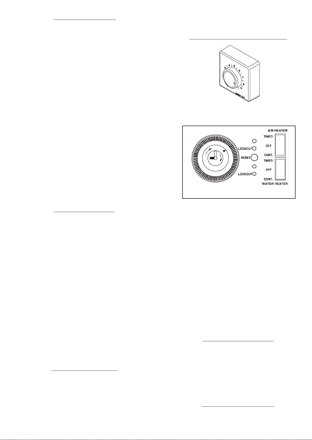
manuals.online logo
Brands
  1. Home
  2. •
  3. Brands
  4. •
  5. Johnson & Starley
  6. •
  7. Heater
  8. •
  9. Johnson & Starley ECONOMAIRE 25 User manual

Johnson & Starley ECONOMAIRE 25 User manual

Complete Economaire range - from left to right:
Economaire 25; Economaire 31; Economaire 50; Economaire 90; Economaire 65 and Economaire 32
WARNING:THISAPPLIANCEMUSTBEEARTHED
IMPORTANT: ITISASTATUTORYREQUIREMENTTHATALLGASAPPLIANCESBEINSTALLEDBYCOMPETENT
PERSONS, (i.e.CORGI REGISTERED INSTALLERS) IN ACCORDANCE WITH THE GAS SAFETY
(INSTALLATION AND USE) REGULATIONS (CURRENT EDITION). FAILURE TO COMPLY WITH THESE
REGULATIONS MAYRESULTINPROSECUTION.
ECONOMAIRE RANGE OF WARM AIR HEATERS
with MODULATING CONTROL
USER INSTRUCTIONS PublicationNo. ZZ1091/2
April 2002
MODULATING CONTROL- HOW IT WORKS
Modulating Control automatically operates your heating system to maintain winter comfort efficiently and
unobtrusively.
You select the comfort level by setting the temperature controller (called the Thermista-stat).
The amount of heat needed depends upon the
difference between the temperature outside the dwelling and your chosen comfort level. The system
automatically adjusts its warm air output to achieve this level.
Examples:
When full heat is needed (during very cold weather, or on initial warm up), the gas burner operates at
full output and the fan runs at maximum speed until the room temperature, determined by the Thermista-
stat setting is reached.
The gas burner will then operate in short firing cycles with the fan running at a reduced speed.
In the event of this appliance being sold or transferred
to anotheruser, THESE instructions must be supplied.
Johnson and Starley prides itself on its ability to supply spare parts quickly and efficiently. If your service engineer indicates a
problem in obtaining a spare part, advise him to contact Johnson and Starley Spares Department at the address below.
Telephone: 01604762881 JOHNSONAND STARLEY Ltd.,
Rhosili Road,
Brackmills,
Fax: 01604767408 Northampton, NN4 7LZ
Johnson & Starley Ltd.
23
Fig. 1
Fig.2
ON
ON
12
93
1. TOLIGHTYOURHEATER
1.1 Ensure that the gas supply to the heater is turned on.
1.2 Set both the “AIR HEATER” and “WATER HEATER”
(if fitted) switches on the time control to the “OFF”
position.
1.3 Turn the Thermista-stat (room temperature control) to
position “9” (see fig. 1).
1.4 Switch on the electrical supply to the heater.
1.5 Set the “AIR HEATER” switch on the time control to
“CONT”After a period of 15-20 seconds the burner
will ignite automatically, indicated by the green LED
light marked ‘ON’ on the indicator panel (see Fig. 2).
Shortly afterwards the air circulation fan will start.
1.6 Adjust the Thermista-stat to the desired setting (see
Section 3).
1.7 The heater will now operate automatically under
thermostatic control.
1.8 If the burner does not ignite the first time, the red
LEDlightmarked‘LOCKOUT’willlight.Ifthis
should occur, check that the gas supply to the
appliance is turned on, wait approximately 10
seconds and then press the button marked ‘RESET’
to re-initiate the ignition sequence.
1.9 If, after carrying out the above instructions several
times, the green light fails to remain lit, contact your
local service engineer.
2. TOSTOPYOURHEATER
2.1 For short periods, e.g. weekends:
Turn the “AIR HEATER” switch to the “OFF”
position, or turn the thermista-stat anticlockwise to
to its minimum setting. This will cause the burner to
extinguish and the heater fan to stop once the heat
exchanger has cooled. When you require the heating
on again, turn to “AIR HEATER” switch to the “ON”
position, or reset the thermista-stat to the desired
setting.
2.2 For longer periods, e.g. a week or summer
shutdown:
Turn the “AIR HEATER” switch to the “OFF”
position, set the Thermista-stat to its minimum
setting, then turn off the electricity supply to the
heater.
WARNING: Do not turn off the electrical
supply when the main burner is lit, as this may
cause damage to the heater.
2.3 IMPORTANT: If summer air circulation is re-
quired, the electrical supply to the heater must
remain on.
3. TEMPERATURECONTROL
3.1 The figures on the thermista-stat dial represent levels
of warmth and when you select a dial number, the
heater will operate automatically to maintain that
level. You will soon find the setting at which you are
most comfortable, but we recommend that you start
at setting 5 and make adjustments up or down until a
satisfactory level is reached.
4.1 You can control the heat to each room by opening
and closing the warm air outlets, but never close
more than half of the outlets at any one time or the
performance of the heating system will be affected.
Warm air outlets in the room where the thermista-stat
is sited should always be open to ensure that the
heating system is controlled properly.
4.2 During the average winter weather, warm air outlets in
rooms not having a thermista-stat should be opened
only as much as is necessary to bring the room to a
comfortable level.
4.3 Overnight in prolonged severe weather, it is better to
set the heater time control to “CONT” and reduce the
setting of the Thermista-stat to provide a general
background heating (i.e. Setting 4). On rising, reset
the Thermista-stat to the normal daily comfort setting
and the room temperature will quickly rise.
4.4 SUMMERAIR CIRCULATION
During hot weather, unheated air can be circulated
around the dwelling, (using the air circulation fan),
by turning the Thermista-stat fully clockwise to the
switched‘SUMMERAIRFLOW’position.
IMPORTANT: If at any time the heater fails to
turn off when there is no demand for heat,
switch off the gas and electrical supply to the
heaterand contact your local service engineer.
5. TIMECONTROLOPERATION
It is worth noting that best economy is achieved at
the lowest setting that you find acceptable.
4. CONTROLOFYOUR HEATINGSYSTEM
5.1 In addition to continuous operation, the Time Control
will provide 24 hour timed operation of the air heater
in 15 minutes increments (1 tappet). “On” periods are
set by moving the required number of tappets in
towards the centre of the dial. For example, a 4 hour
“on” period will require 16 tappets set to the “on”
position at the required time.
6. AIRFILTER
6.1 The air filter is located where the return air ducting
connects to the air heater.
6.2 IMPORTANT: during periods where the heater is
being used constantly, the air filter should be
checked at regular intervals.
6.3 TOCLEANTHEFILTER: cleaningthefilterwill
depend on the filter type. It will be either:
a) PassiveFilter: withdraw the filter from the heater,
clean with a soft brush or vacuum cleaner and refit.
b) Electronic Filter: withdraw the filter as above and
remove surface dust with a soft brush. If the filter
medium is soiled, replace as directed in the filter kit
instructions. DO NOTATTEMPT TO CLEAN OR
WASHTHE FILTERMEDIUM!
NOTE:if you allow the filter to become clogged the
heater effeciency will be greatly reduced.
INNEW DWELLINGS: cleanthefilter onceaweek
for the first month or two to clear builder’s dust.
7. MAINTENANCE
7.1 It is recommended that a full maintenance check on
your appliance be made at least once a year and that
a service contract is taken out at the end of the
guarantee period.Your local gas supplier will be able
to provide details of arrangements for this service.
Note:This appliance SHOULDbe checked and
maintained periodically by aqualifiedprofessional
orcompetentperson.
8. POWER CUTS
8.1 If you experience an electrical power cut your air
heater will cease to operate. When the electrical
supply is restored, the heater will work normally but
the Time Control WILL require resetting.
9. TROUBLESHOOTING
9.1 Check that the Thermista-stat and Time Control are
set correctly to your requirements and that at least
half of the warm air outlets are open, especially in the
room where the Thermista-stat is located.
9.2 Check that the air filter is not clogged, if so clean as
detailed in Section 6.
9.3 If the LOCKOUTis lit, waitforapproximately 10
seconds and then press the RESET button.
9.4 If the heater will still not operate correctly, contact
your local service engineer.
Servicearrangements:
a. for new dwellings, servicing is usually supplied
for a specific period under arrangements made
by the building contractor.
b. localAuthorities often have their own special
arrangements.
c. if the above do not apply, contact your local
service engineer, or the Service department at
Johnson & Starley Ltd.
10. IFYOU SMELLGAS
DO NOT operate any electrical switches, or use
a naked flame.
TURN OFF the gas supply.
VENTILATE the area by opening doors and
windows.
CALLOUT your local gas supplier.
11. CLEANING
11.1 If necessary, the heater cabinet may be cleaned using
a mild soap solution. DO NOT use abrasive pads or
scourers.
IMPORTANT
FORYOURHEATERTO WORKEFFICIENTLYANDFORYOUR HEATINGSYSTEMTOPERFORM
SATISFACTORILY, IT ISABSOLUTELYESSENTIALTO OBSERVETHE FOLLOWING:
1. DOKEEPCLEAN,andmakesureyouDONOTOBSTRUCTanygrillesontheheater,intheheatercompartment,orinany
walls,windowsordoorsofthebuilding.
2. DOCLEANANDREFITtheairfilteratleastoncepermonth.
3. DONOTPLACEANYTHING(clothing,linenetc.)incontactwiththeairheateroritsfluepipe.
4. DONOTUSE theheatercompartmentforstorage orairing.
5. DONOTturnoffthemains electricitysupplyto theairheater untilthegas supplyhasbeenturnedoff.
NOTE:Ifyouareawareof,orsuspect,afaultOFANYKINDthe heaterMUSTNOTbeused.Turnoffthegasandelectrical
suppliestotheheaterandcontactyourserviceengineer!
23
Fig. 1
Fig.2
ON
ON
12
93
1. TOLIGHTYOURHEATER
1.1 Ensure that the gas supply to the heater is turned on.
1.2 Set both the “AIR HEATER” and “WATER HEATER”
(if fitted) switches on the time control to the “OFF”
position.
1.3 Turn the Thermista-stat (room temperature control) to
position “9” (see fig. 1).
1.4 Switch on the electrical supply to the heater.
1.5 Set the “AIR HEATER” switch on the time control to
“CONT”After a period of 15-20 seconds the burner
will ignite automatically, indicated by the green LED
light marked ‘ON’ on the indicator panel (see Fig. 2).
Shortly afterwards the air circulation fan will start.
1.6 Adjust the Thermista-stat to the desired setting (see
Section 3).
1.7 The heater will now operate automatically under
thermostatic control.
1.8 If the burner does not ignite the first time, the red
LEDlightmarked‘LOCKOUT’willlight.Ifthis
should occur, check that the gas supply to the
appliance is turned on, wait approximately 10
seconds and then press the button marked ‘RESET’
to re-initiate the ignition sequence.
1.9 If, after carrying out the above instructions several
times, the green light fails to remain lit, contact your
local service engineer.
2. TOSTOPYOURHEATER
2.1 For short periods, e.g. weekends:
Turn the “AIR HEATER” switch to the “OFF”
position, or turn the thermista-stat anticlockwise to
to its minimum setting. This will cause the burner to
extinguish and the heater fan to stop once the heat
exchanger has cooled. When you require the heating
on again, turn to “AIR HEATER” switch to the “ON”
position, or reset the thermista-stat to the desired
setting.
2.2 For longer periods, e.g. a week or summer
shutdown:
Turn the “AIR HEATER” switch to the “OFF”
position, set the Thermista-stat to its minimum
setting, then turn off the electricity supply to the
heater.
WARNING: Do not turn off the electrical
supply when the main burner is lit, as this may
cause damage to the heater.
2.3 IMPORTANT: If summer air circulation is re-
quired, the electrical supply to the heater must
remain on.
3. TEMPERATURECONTROL
3.1 The figures on the thermista-stat dial represent levels
of warmth and when you select a dial number, the
heater will operate automatically to maintain that
level. You will soon find the setting at which you are
most comfortable, but we recommend that you start
at setting 5 and make adjustments up or down until a
satisfactory level is reached.
4.1 You can control the heat to each room by opening
and closing the warm air outlets, but never close
more than half of the outlets at any one time or the
performance of the heating system will be affected.
Warm air outlets in the room where the thermista-stat
is sited should always be open to ensure that the
heating system is controlled properly.
4.2 During the average winter weather, warm air outlets in
rooms not having a thermista-stat should be opened
only as much as is necessary to bring the room to a
comfortable level.
4.3 Overnight in prolonged severe weather, it is better to
set the heater time control to “CONT” and reduce the
setting of the Thermista-stat to provide a general
background heating (i.e. Setting 4). On rising, reset
the Thermista-stat to the normal daily comfort setting
and the room temperature will quickly rise.
4.4 SUMMERAIR CIRCULATION
During hot weather, unheated air can be circulated
around the dwelling, (using the air circulation fan),
by turning the Thermista-stat fully clockwise to the
switched‘SUMMERAIRFLOW’position.
IMPORTANT: If at any time the heater fails to
turn off when there is no demand for heat,
switch off the gas and electrical supply to the
heaterand contact your local service engineer.
5. TIMECONTROLOPERATION
It is worth noting that best economy is achieved at
the lowest setting that you find acceptable.
4. CONTROLOFYOUR HEATINGSYSTEM
5.1 In addition to continuous operation, the Time Control
will provide 24 hour timed operation of the air heater
in 15 minutes increments (1 tappet). “On” periods are
set by moving the required number of tappets in
towards the centre of the dial. For example, a 4 hour
“on” period will require 16 tappets set to the “on”
position at the required time.
6. AIRFILTER
6.1 The air filter is located where the return air ducting
connects to the air heater.
6.2 IMPORTANT: during periods where the heater is
being used constantly, the air filter should be
checked at regular intervals.
6.3 TOCLEANTHEFILTER: cleaningthefilterwill
depend on the filter type. It will be either:
a) PassiveFilter: withdraw the filter from the heater,
clean with a soft brush or vacuum cleaner and refit.
b) Electronic Filter: withdraw the filter as above and
remove surface dust with a soft brush. If the filter
medium is soiled, replace as directed in the filter kit
instructions. DO NOTATTEMPT TO CLEAN OR
WASHTHE FILTERMEDIUM!
NOTE:if you allow the filter to become clogged the
heater effeciency will be greatly reduced.
INNEW DWELLINGS: cleanthefilter onceaweek
for the first month or two to clear builder’s dust.
7. MAINTENANCE
7.1 It is recommended that a full maintenance check on
your appliance be made at least once a year and that
a service contract is taken out at the end of the
guarantee period.Your local gas supplier will be able
to provide details of arrangements for this service.
Note:This appliance SHOULDbe checked and
maintained periodically byaqualifiedprofessional
orcompetentperson.
8. POWER CUTS
8.1 If you experience an electrical power cut your air
heater will cease to operate. When the electrical
supply is restored, the heater will work normally but
the Time Control WILL require resetting.
9. TROUBLESHOOTING
9.1 Check that the Thermista-stat and Time Control are
set correctly to your requirements and that at least
half of the warm air outlets are open, especially in the
room where the Thermista-stat is located.
9.2 Check that the air filter is not clogged, if so clean as
detailed in Section 6.
9.3 If the LOCKOUTis lit, waitforapproximately 10
seconds and then press the RESET button.
9.4 If the heater will still not operate correctly, contact
your local service engineer.
Servicearrangements:
a. for new dwellings, servicing is usually supplied
for a specific period under arrangements made
by the building contractor.
b. localAuthorities often have their own special
arrangements.
c. if the above do not apply, contact your local
service engineer, or the Service department at
Johnson & Starley Ltd.
10. IFYOU SMELLGAS
DO NOT operate any electrical switches, or use
a naked flame.
TURN OFF the gas supply.
VENTILATE the area by opening doors and
windows.
CALLOUT your local gas supplier.
11. CLEANING
11.1 If necessary, the heater cabinet may be cleaned using
a mild soap solution. DO NOT use abrasive pads or
scourers.
IMPORTANT
FORYOURHEATERTO WORKEFFICIENTLYANDFORYOUR HEATINGSYSTEMTOPERFORM
SATISFACTORILY, IT ISABSOLUTELYESSENTIALTO OBSERVETHE FOLLOWING:
1. DOKEEPCLEAN,andmakesureyouDONOTOBSTRUCTanygrillesontheheater,intheheatercompartment,orinany
walls,windowsordoorsofthebuilding.
2. DOCLEANANDREFITtheairfilteratleastoncepermonth.
3. DONOTPLACEANYTHING(clothing,linenetc.)incontactwiththeairheateroritsfluepipe.
4. DONOTUSE theheatercompartmentforstorage orairing.
5. DONOTturnoffthemains electricitysupplyto theairheater untilthegas supplyhasbeenturnedoff.
NOTE:Ifyouareawareof,orsuspect,afaultOFANYKINDthe heaterMUSTNOTbeused.Turnoffthegasandelectrical
suppliestotheheaterandcontactyourserviceengineer!
Complete Economaire range - from left to right:
Economaire 25; Economaire 31; Economaire 50; Economaire 90; Economaire 65 and Economaire 32
WARNING:THISAPPLIANCE MUSTBEEARTHED
IMPORTANT: ITISASTATUTORYREQUIREMENTTHATALLGASAPPLIANCES BEINSTALLED BYCOMPETENT
PERSONS, (i.e.CORGI REGISTERED INSTALLERS) IN ACCORDANCE WITH THE GAS SAFETY
(INSTALLATION AND USE) REGULATIONS (CURRENT EDITION). FAILURE TO COMPLY WITH THESE
REGULATIONS MAYRESULTINPROSECUTION.
ECONOMAIRE RANGE OF WARM AIR HEATERS
with MODULATING CONTROL
USER INSTRUCTIONS PublicationNo. ZZ1091/2
April 2002
MODULATING CONTROL- HOW IT WORKS
Modulating Control automatically operates your heating system to maintain winter comfort efficiently and
unobtrusively.
You select the comfort level by setting the temperature controller (called the Thermista-stat).
The amount of heat needed depends upon the
difference between the temperature outside the dwelling and your chosen comfort level. The system
automatically adjusts its warm air output to achieve this level.
Examples:
When full heat is needed (during very cold weather, or on initial warm up), the gas burner operates at
full output and the fan runs at maximum speed until the room temperature, determined by the Thermista-
stat setting is reached.
The gas burner will then operate in short firing cycles with the fan running at a reduced speed.
In the event of this appliance being sold or transferred
to anotheruser, THESE instructions must be supplied.
Johnson and Starley prides itself on its ability to supply spare parts quickly and efficiently. If your service engineer indicates a
problem in obtaining a spare part, advise him to contact Johnson and Starley Spares Department at the address below.
Telephone: 01604762881 JOHNSONAND STARLEY Ltd.,
Rhosili Road,
Brackmills,
Fax: 01604767408 Northampton, NN4 7LZ
Johnson & Starley Ltd.

Other manuals for ECONOMAIRE 25

1

This manual suits for next models

5

Other Johnson & Starley Heater manuals

Johnson & Starley JANUS 6 User manual

Johnson & Starley

Johnson & Starley JANUS 6 User manual

Johnson & Starley HI-SPEC J32P User guide

Johnson & Starley

Johnson & Starley HI-SPEC J32P User guide

Johnson & Starley ECONOMAIRE 6 Instruction sheet

Johnson & Starley

Johnson & Starley ECONOMAIRE 6 Instruction sheet

Johnson & Starley HI-SPEC J25 User guide

Johnson & Starley

Johnson & Starley HI-SPEC J25 User guide

Johnson & Starley JANSTAR Mk 2 User guide

Johnson & Starley

Johnson & Starley JANSTAR Mk 2 User guide

Johnson & Starley WARMCAIR C26D User guide

Johnson & Starley

Johnson & Starley WARMCAIR C26D User guide

Johnson & Starley HI-SPEC J40 User guide

Johnson & Starley

Johnson & Starley HI-SPEC J40 User guide

Johnson & Starley Economaire 31 User guide

Johnson & Starley

Johnson & Starley Economaire 31 User guide

Johnson & Starley WARMCAIR C10D User guide

Johnson & Starley

Johnson & Starley WARMCAIR C10D User guide

Johnson & Starley JB25P MK 5 User guide

Johnson & Starley

Johnson & Starley JB25P MK 5 User guide

Johnson & Starley SCT 75-75 G Guide

Johnson & Starley

Johnson & Starley SCT 75-75 G Guide

Johnson & Starley WARMCAIR C10D User manual

Johnson & Starley

Johnson & Starley WARMCAIR C10D User manual

Johnson & Starley HI-SPEC M31 User guide

Johnson & Starley

Johnson & Starley HI-SPEC M31 User guide

Johnson & Starley ECONOMAIRE 90 User guide

Johnson & Starley

Johnson & Starley ECONOMAIRE 90 User guide

Johnson & Starley HI-SPEC J50P User guide

Johnson & Starley

Johnson & Starley HI-SPEC J50P User guide

Johnson & Starley WARMCAIR C16D User manual

Johnson & Starley

Johnson & Starley WARMCAIR C16D User manual

Johnson & Starley HI-SPEC J50 User guide

Johnson & Starley

Johnson & Starley HI-SPEC J50 User guide

Johnson & Starley WARMCAIR C10D User manual

Johnson & Starley

Johnson & Starley WARMCAIR C10D User manual

Johnson & Starley ECONOMAIRE 32 User guide

Johnson & Starley

Johnson & Starley ECONOMAIRE 32 User guide

Johnson & Starley AQUAIR S-25 User guide

Johnson & Starley

Johnson & Starley AQUAIR S-25 User guide

Johnson & Starley HI-SPEC J90 User guide

Johnson & Starley

Johnson & Starley HI-SPEC J90 User guide

Johnson & Starley WARMCAIR C10DW User manual

Johnson & Starley

Johnson & Starley WARMCAIR C10DW User manual

Johnson & Starley JANSTAR User guide

Johnson & Starley

Johnson & Starley JANSTAR User guide

Johnson & Starley WARMCAIR C36U User guide

Johnson & Starley

Johnson & Starley WARMCAIR C36U User guide

Popular Heater manuals by other brands

Technotherm Frost Guard FW 501 Installation and operating instructions

Technotherm

Technotherm Frost Guard FW 501 Installation and operating instructions

Olimpia splendid Caldostile M Instructions for installation, use and maintenance

Olimpia splendid

Olimpia splendid Caldostile M Instructions for installation, use and maintenance

Campingaz IR 5000 Instructions for use

Campingaz

Campingaz IR 5000 Instructions for use

KDK FY-3009U1 operation instruction

KDK

KDK FY-3009U1 operation instruction

Stelpro CW750-CW1000 user guide

Stelpro

Stelpro CW750-CW1000 user guide

Orbegozo CVT 3400 instruction manual

Orbegozo

Orbegozo CVT 3400 instruction manual

Desa RCLP155 owner's manual

Desa

Desa RCLP155 owner's manual

Kubota 77700-V5247 installation manual

Kubota

Kubota 77700-V5247 installation manual

Fagor TRV-6100 Instructions for use

Fagor

Fagor TRV-6100 Instructions for use

VeriSmart RFC1000 Original operating instructions

VeriSmart

VeriSmart RFC1000 Original operating instructions

Bionaire BOH2503D manual

Bionaire

Bionaire BOH2503D manual

Uberhaus PH-891 Operator's manual

Uberhaus

Uberhaus PH-891 Operator's manual

HELLER FSK 505 Mounting and operating instructions

HELLER

HELLER FSK 505 Mounting and operating instructions

Geko G80409 Translation of the original operating instructions

Geko

Geko G80409 Translation of the original operating instructions

Rowi HHL 2000/3/3 Instructions for use

Rowi

Rowi HHL 2000/3/3 Instructions for use

Vigor Equipment V4891-1.0 operating instructions

Vigor Equipment

Vigor Equipment V4891-1.0 operating instructions

Rotel 7042CH Instructions for use

Rotel

Rotel 7042CH Instructions for use

UFESA FH Crux Dual Blue instruction manual

UFESA

UFESA FH Crux Dual Blue instruction manual

manuals.online logo
manuals.online logoBrands
  • About & Mission
  • Contact us
  • Privacy Policy
  • Terms and Conditions

Copyright 2025 Manuals.Online. All Rights Reserved.