manuals.online logo
Brands
  1. Home
  2. •
  3. Brands
  4. •
  5. Johnson Controls
  6. •
  7. Controllers
  8. •
  9. Johnson Controls VAP Series User manual

Johnson Controls VAP Series User manual

1
601U-B01A-NC-Issue Date 11 2013
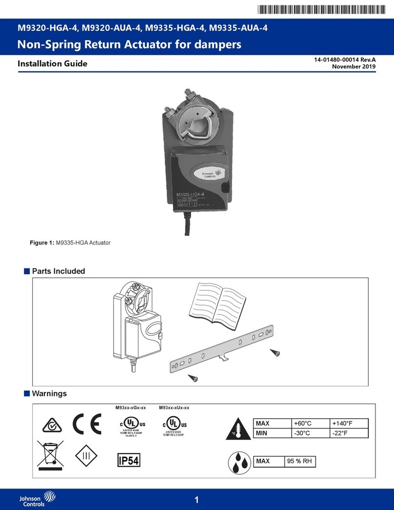
VAP Series balancing valve actuator -Installation Instructions
VAP系列平衡阀执行器 -安装说明
VAP1000-24-C
用于VPA系列DN50/65平衡阀
For VPA Series Balancing Valve DN50/65
VAP500-24-C
用于VPA系列DN25-50平衡阀
For VPA Series Balancing Valve DN25-50
接线图 Wiring Diagram
基本参数 Basic Parameter
601U-B01A-NC-Issue Date 11 2013
This document is subject to change without notice 本文档如有变化,恕不另行通知
VAP3000-24-C
用于VPA系列DN80-150平衡阀
For VPA Series Balancing Valve DN80-150
型号
Model VAP500-24-C VAP1000-24-C VAP3000-24-C 型号
Model VAP500-24-C/VAP1000-24-C/VAP3000-24-C
额定输出力
Rating Force 500N 1000N 3000N 控制信号
Control Signal 0(2)~10VDC, 0(4)~20mA
电源
Power Supply 24V AC 阀位反馈信号
Feedback Signal 0(2)~10VDC,0(4)~20mA
控制类型
Type of Control
比例调节型
proportional
电压输入阻抗
Voltage Input Impedance >100K
功率消耗
Power Consumption 7.5VA 15VA 电流输入阻抗
Current Input Impedance <0.167K
最大行程
Max. Stroke 22mm 43mm 电压输出负载要求
Voltage Output Load >1K
运行速度
Running Speed 3.85s/mm(50Hz) 3.2s/mm(50Hz) 电流输出负载要求
Current Output Load <0.5K
产品净重
Net Weight of Product 1.7Kg 5.2Kg 上下极限死区范围
Up and Down Dead Band ≤2.5%
双向灵敏度
Sensitivity 高灵敏度≤1.0%;低灵敏度≤1.5% 高灵敏度≤1.5%;低灵敏度≤2.0% 环境湿度
Ambient Humidity ≤95% RH(40℃)
机壳防护等级
Enclosure Rating IP54 环境温度
Ambient Temperature -10℃~50℃
调试说明
A. 安装执行器及阀门(具体操作见安装说明)。
B. 关闭执行器电源开关(VAP3000-24-C电源开关在执行器底板后侧下方位置,
VAP500-24-C/VAP1000-24-C无电源开关)。
C. 接线完毕(见接线说明)。
D. 将拨码开关设定到需要的位置(拨码开关可带电设置)。
E. 打开执行器电源开关。
F. 自适应(出厂默认为上电自适应):此步骤的目的为使执行器与阀体进行行程匹配:
1) 打开执行器电源,执行器自动进入自适应状态。
2) 运行指示灯(RUN)闪烁(频率约为1Hz),执行器轴先伸出运行至下极限,然
后在缩进运行至上极限。(此时执行器将不受控制信号的控制)
3) 约3分钟后指示灯停止闪烁,此时执行器与阀体的自适应结束,阀体与执行器的
配合调节完成。此时执行器的运行方向由控制信号控制
G. 开度调节:通过调节开度电位器实现阀门最大开度在100%至30%范围内连续调节,
灵活的调节阀体内的相对流量与其开度间关系: 100%-40%开度区间内均分为高
低灵敏度,40%-30%开度区间内均为低灵敏度。
注明:1. 当执行器在通电情况下,若需自适应,按下执行器电路板上的红色按键3s以上,执行器进入
自适应状态。自适应现象与(2)(3)现象相同。
2. 如需更改自适应模式,可通过调节第七位拨码进行自适应模式选择设定,见拨码开关设定说明。
Wiring Diagram
A. Assemble the actuator with valve body. ( Please refer to installation instructions)
B. Turn off the power switch of actuator.(Power switch is under the right side of VAP3000-24-C
actuator, no power switch for VAP500-24-C/VAP1000-24-C)
C. Finish the wiring. (Please refer to wiring diagram)
D. Set DIP switches as required. (DIP switches can be set when power on)
E. Turn on the power switch of actuator.
F. Self-stroking. (Factory setting: self-stroking starts automatically when power on each time) :
The purpose of this step is to make the actuator matching with the stroke of the valve body.
1) Turn on the power switch, self-stroking starts automatically.
2) Running light (RUN) flickers (frequency 1Hz. Actuator axes extends until down limit position,
then retracts to up limit position. This moment, actuator can not be controlled by control
signal.)
3) Running light (RUN) stops flickering after appr. 3 minutes when self-stroking finish. Now
actuator matches the stroke of the valve body. Actuator can be controlled by control signal.
G. Aperture regulating. Biggest stroke of the valve can be adjusted from 30%~100% of its original
stroke by regulating the aperture potentiometer. Flow rate can be regulated neatly.(40%~30%,
only low sensitivity of control signal. 100%~40% high and low sensitivity selectable.)
Remarks:1. When power on, self-stroking can also be operated manually by pressing the red self-
stroking button on PCB for over 3 seconds. Self-stroking cycle repeats as step 2) & 3).
2. If you want to change self-stroking mode, adjust the seventh DIP switch. (Please refer to
DIP switch setting)
接线端子Terminal
B,O 24VAC电源/ 24VAC Power supply
O控制信号/反馈信号公共端COM for control/feedback signal
E控制信号Control signal
Y反馈信号Feedback signal
2
VAP Series balancing valve actuator -Installation Instructions
VAP系列平衡阀执行器 -安装说明
601U-B01A-NC-Issue Date 11 2013
23 4
1
ON
OFF
S2
23 4
1
S3
控制信号 Control signal:0~10VDC
阀位反馈信号 Feedback signal:0~10VDC
工作模式 Operating mode:RA
断信号模式 Losing control signal mode:DW
控制信号 Control signal:4~20mA
阀位反馈信号 Feedback signal:4~20mA
工作模式 Operating mode:RA
断信号模式 Losing control signal mode:DW
例1
S2、S3拨码开关设定 S2, S3 DIP Switch Setting
拨码
DIP
功能
Function
设定值功能描述
Description
S2
1
控制/阀位反馈信号起始点
设定
Starting of control /
feedback signal
ON 20%: 控制/阀位反馈信号起始点为20%(适用于控制/阀位反馈信号为4~20mA或2~10VDC)
20%: The starting control / feedback signal is 20% (namely 4~20mA or 2~10VDC)
OFF 0: 控制/阀位反馈信号起始点为0(适用于控制/阀位反馈信号为0~20mA或0~10VDC)(出厂默认设定)
0: The starting control / feedback signal is 0 (namely 0~20mA or 0~10VDC) (factory setting)
2控制信号类型 设定
Type of control signal
ON II: 控制信号为电流型
II: current signal
OFF UI: 控制信号为电压型(出厂默认设定)
UI: voltage signal (factory setting)
3输入信号阻抗匹配 设定
Selection of control signal
ON UI: 控制信号为电压型(出厂默认设定)
UI: voltage signal (factory setting)
OFF II: 控制信号为电流型
II: current signal
4阀位反馈信号类型 设定
Type of feedback signal
ON IO: 阀位反馈信号为电流型
IO: current signal
OFF UO: 阀位反馈信号为电压型(出厂默认设定)
UO: voltage signal (factory setting)
S3
1工作模式 设定
Operating mode
ON DA: 控制信号增大时执行器轴伸出运行,控制信号减小时执行器主轴缩进运行
DA: when control signal is increasing, the actuator axes extends
OFF RA: 控制信号增大时执行器轴缩进运行,控制信号减小时执行器主轴伸出运行 (出厂默认设定)
RA: when controls signal is increasing, the actuator axes retracts (factory setting)
2
断信号模式 设定
Losing control signal
mode
ON
DW: 当控制信号类型设定为电压型或电流型时,此时如果信号线被切断,执行器内部会自动提供一个最小控制信号。
(出厂默认设定)
DW: When lose control signal (voltage type), the minimum control signal (will be applied automatically)
When lose control signal (current type), the minimum control signal (will be applied automatically) (factory setting)
OFF
UP: 1) 当控制信号类型设定为电压型时,此时如果信号线被切断,执行器内部会自动提供一个最大控制信号。
2) 当控制信号类型设定为电流型时,此时如果信号线被切断,执行器内部会自动提供一个最小控制信号。
UP: When lose control signal (voltage type), the maximum control signal (will be applied automatically)
When lose control signal (current type), the minimum control signal (will be applied automatically)
3自适应模式设定
Self-stroking mode
ON DF: 执行器为上电自适应模式(出厂默认设定)。
DF: Power up each time, self-stroking starts automatically (factory setting)
OFF RF: 执行器为手动自适应模式。
RF: Self-stroking starts only when press the red self-stroking button manually
4
灵敏度设定
Sensitivity
ON
HS: VAP500-24-C/VAP1000-24-C控制信号高灵敏度≤1.0% (100%~40%) ; ≤1.5% (40%~30%)
VAP3000-24-C控制信号高灵敏度≤1.5% (100%~40%) ; ≤2% (40%~30%)
HS: The high sensitivity of control signal (VAP500-24-C/VAP1000-24-C) ≤1.0% (100%~40%) ; ≤1.5% (40%~30%)
The high sensitivity of control signal (VAP3000-24-C) ≤1.5% (100%~40%) ; ≤2% (40%~30%)
OFF
LS: VAP500-24-C/VAP1000-24-C控制信号低灵敏度≤1.5% (100%~30%) (出厂默认设定)
VAP3000-24-C控制信号低灵敏度≤2% (100%~30%) (出厂默认设定)
LS: The low sensitivity of control signal (VAP500-24-C/VAP1000-24-C) ≤1.5% (100%~30%) (factory setting)
The low sensitivity of control signal (VAP3000-24-C) ≤2% (100%~30%) (factory setting)
S2、S3拨码开关设定示例 S2, S3Setting Example
例2
数码管功能说明(仅限VAP3000-24-C)
标配功能:
—运行指示灯(RUN):此指示灯为红绿双色灯,当执行器轴缩进运行的时候,运
行指示灯的红灯亮;执行器轴伸出运行的时候,运行指示灯绿灯亮,当进行自适
应操作时,红绿双色灯同时闪烁(频率为1Hz)。
—故障指示灯(ERR):当执行器出现故障时,故障指示灯亮。
—数码管:(从左至右四位数码管,第一位为功能位,第2,3,4位为数字位)
1)数码管显示及含义:
Additional Function (Only for VAP3000-24-C)
Basic function:
—Running light(RUN):Red and green double color light. When actuator axes retracts,
running light shows red; when actuator axes extends, running light shows green.; when do
"self-stroking", running light flickering both red and green (1Hz).
—Warning light(ERR):When actuator has problem, warning light will be lighting.
—LED:(from left to right, the first one is function bit, the second to the forth are numerical bits)
1) Description of LED:
出厂默认设定 factory setting 用户设定 user setting
功能位
Function Bit
含义
Description
数字位
Numerical Bit
含义
Description
A开度百分数
Show aperture value
30-100之间连续变化
Number between 30-100
当前开度值,其显示值为百分数
Present aperture value (percent)
C
数字位显示值为输入信号
Show control signal on
Numerical bit
0~100之间数值
Number between 0~100
输入信号值,其显示值为百分数,例如输入信号0~10V,当输入信号为1V时,此时的显示值为
1/10*100=10
Control signal (percent) 0~10V. For example, control signal type is 0~10V, When control signal is 1V, there
will be shown 1/10*100=10
F
数字位显示值为反馈信号
Show feedback signal on
Numerical bit
0~100之间数值
Number between 0~100
反馈信号值,其显示值为百分数,例如反馈信号为0~10V,当反馈信号为1V时,此时 的显示值为
1/10*100=10
Feedback signal (percent) 0~10V. For example, feedback signal type is 0~10V, When control signal is 1V,
there will be shown 1/10*100=10
23 4
1
S3
ON
OFF 23 4
1
S2
3
601U-B01A-NC-Issue Date 11 2013
VAP Series balancing valve actuator -Installation Instructions
VAP系列平衡阀执行器 -安装说明
S2, S3 dip switch
拔码开关
Connection terminal
接线端子
Connection terminal
接线端子
Self-stroking button
自适应按钮
Self-stroking button
自适应按钮
Aperture potentiometer
开度调节电位器
Power light
电源指示灯
Running light
工作指示灯
Aperture potentiometer
开度调节电位器
Running light
运行指示灯
故障指示灯
数码管功能 数码管数字位
1 2 3 4
1 2 3 4
2)数码管数字位,包括3为数码管,其最小显示值为0,最大显示值为100,显示精
度为±1
3)当执行器正常运行时,数码管在C和F直接交替显示,即输入信号与执行器反馈信
号交替显示。
故障报警功能:
—自适应过程不正常故障报警:
黄色报警指示灯点亮
执行器运行状态:当控制信号>总量程的50%时,执行器轴缩进运行到上极限位
置,当控制信号<总量程的50%时,执行器轴伸出运行到下极限位置,阀位反馈
信号始终输出总量程的50%±1%。
数码管显示:功能位:交替显示C与F;数字位显示:交替显示当前控制信号值并
且阀位反馈信号显示值50(始终显示为50)。
—不能运行指定位置故障报警:
黄色报警指示灯点亮
执行器运行状态:执行器停止运行
数码管显示:功能位:交替显示C与F;数字位显示:交替显示当前控制信号C与
发生故障时的F显示值。
2) Numerical bit of LED ( displayed value: Min.1, Max.100, precision ±1)
3) When actuator is running correctly, it shows "C" or "F" alternately in the LED, it
means that "control signal" and "feedback signal" shows alternately.
Failure warning function:
—Failure when doing self-stroking:
Yellow warning light is lighting
Running status of actuator: when control signal is bigger than 50% of signal range,
actuator axes retracts to up limit position; when control signal is smaller than 50%
of signal range, actuator axes extends to down limit position; feedback signal
keeps 50%±1%.
LED status: function bit shows "C" or "F" alternately; numerical bits show the
present control signal and feedback signal 50 (not the present feedback position)
—Failure when actuator couldn't run to appointed position:
Yellow warning light is lighting
Running status of actuator: actuator stops
LED status: function bit shows "C" or "F" alternately; numerical bits show the
present control signal value and feedback signal when problem hanppened.
电路板 PCB
接线说明 Prepare for wiring
3
Screw the waterproof joint after wiring.
接完线,装上防水接头
Assemble the top cover and tighten the screws.
4
装上前盖,拧上螺丝,完成接线
Remove the top cover, prepare to wire.
1
Top Cover
拆下上盖后进行接线
上盖
Unscrew the waterproof joint, wire goes through
the hole of waterproof joint, connect the wire to
the terminals as required.
2接线时,拧下箭头所示防水接头,线穿过防水接头,
按要求接到接线端子
waterproof Joint
防水接头
3
Screw the waterproof joint after wiring.
接完线,装上防水接头
Assemble the top cover and tighten the screws.
4
装上前盖,拧上螺丝,完成接线
Remove the front cover, prepare to wire.
1
Front Cover
拆下前盖后进行接线
前盖
Unscrew the waterproof joint, wire goes through
the hole of waterproof joint, connect the wire to
the terminals as required.
2接线时,拧下箭头所示防水接头,线穿过防水接头,
按要求接到接线端子
waterproof Joint
防水接头
VAP3000-24-CVAP500-24-C/VAP1000-24-C
VAP500-24-C/VAP1000-24-C
VAP3000-24-C
4
VAP Series balancing valve actuator -Installation Instructions
VAP系列平衡阀执行器 -安装说明
601U-B01A-NC-Issue Date 11 2013
手动功能的使用说明 Manual function
VAP500-24-C/VAP1000-24-C
外形尺寸图 Dimensions
3 41 2
Insert Inner hexagon spanner to the manual.
Turn anticlockwise for actuator axes extends;
Turn clockwise for actuator axes retracts.
After finished the manual operation, just take
down the Inner hexagon spanner.
Shut off power supply and prepare for manual
operation.
关闭电源,准备进行手动操作。 将内六角扳手插入上盖顶部的手动孔内。 逆时针旋转内六角扳手,驱动器主轴伸出运行;
顺时针旋转内六角扳手,驱动器主轴缩进运行。
手动操作完毕,将内六角扳手取出即可。
S=5mm
俯视图
( Top View )
Cut off power supply before operating manual.
!
内六角扳手
Inner hexagon spanner
3 41 2
Pull out the crank and go round 180 degree.
Press down the knob to limit position, keep
pressing and start to turn the crank.
After finished the manual operation, release the
knob, and pull up the knob to the up limit
position.
Shut off and prepare for manual operation.
关闭电源,做好手动准备。 拔出手柄,并把手柄旋转180°。 下压手轮至下极限位置,保持下压力,开始摇动手
轮,实现手动操作功能。
完成手动操作后,松开手柄,拔起手轮并确保手轮
处于上极限位置。
180°
360°
Power
switch
手轮
Knob 手柄
Crank
1. 逆时针转动手柄,驱动器主轴缩进运行;
2. 顺时针转动手柄,驱动器主轴伸出运行;
1. Turn anticlockwise for actuator axes retracts;
2. Turn clockwise for actuator axes extends.
( Any release of press
is not allowed when
the crank running.)
VAP3000-24-C
安装说明 Installation
3 41 2
Keep the actuator’s axes and the valve’s
stem concentric, make these two connecting
faces and keep coinciding. Then lock the two
screws on the clip.
Pull the fixed fitting to the groove and lock
by two screws.
The status after assembled.Prepare for assembling the actuator, take
down the fixed fitting firstly, and then
disentangle the clip.
先取下滑块,驱动器夹子松开,做好装配准备。 使驱动器主轴与阀杆同心,并且端面重合;将驱动
器置于阀体凸台上,锁紧夹子上的两个螺丝。
将滑块装入驱动器凹槽内,用两个螺丝锁紧。 正面装配完成后状态。
VAP500-24-C/VAP1000-24-C VAP3000-24-C

Other manuals for VAP Series

1

This manual suits for next models

3

Other Johnson Controls Controllers manuals

Johnson Controls VA9208-GG Series User manual

Johnson Controls

Johnson Controls VA9208-GG Series User manual

Johnson Controls G77 Series User manual

Johnson Controls

Johnson Controls G77 Series User manual

Johnson Controls MS-FEC2611 Series User manual

Johnson Controls

Johnson Controls MS-FEC2611 Series User manual

Johnson Controls EasyIO FW-08 V3 User manual

Johnson Controls

Johnson Controls EasyIO FW-08 V3 User manual

Johnson Controls FMS-1655L User manual

Johnson Controls

Johnson Controls FMS-1655L User manual

Johnson Controls VA-77 Series User manual

Johnson Controls

Johnson Controls VA-77 Series User manual

Johnson Controls VMA18 Series User manual

Johnson Controls

Johnson Controls VMA18 Series User manual

Johnson Controls tyco Power Neo HS2016 User manual

Johnson Controls

Johnson Controls tyco Power Neo HS2016 User manual

Johnson Controls TEC3010 User manual

Johnson Controls

Johnson Controls TEC3010 User manual

Johnson Controls VA-8052 User manual

Johnson Controls

Johnson Controls VA-8052 User manual

Johnson Controls VG1600 Series User manual

Johnson Controls

Johnson Controls VG1600 Series User manual

Johnson Controls M9310-HGA-3 User manual

Johnson Controls

Johnson Controls M9310-HGA-3 User manual

Johnson Controls Metasys NCE25 series User manual

Johnson Controls

Johnson Controls Metasys NCE25 series User manual

Johnson Controls PENN ACT2 Service manual

Johnson Controls

Johnson Controls PENN ACT2 Service manual

Johnson Controls System 350 P352AB Series User manual

Johnson Controls

Johnson Controls System 350 P352AB Series User manual

Johnson Controls Penn P216 User manual

Johnson Controls

Johnson Controls Penn P216 User manual

Johnson Controls TEC3000 Series User manual

Johnson Controls

Johnson Controls TEC3000 Series User manual

Johnson Controls FAC2612-2 User manual

Johnson Controls

Johnson Controls FAC2612-2 User manual

Johnson Controls FX-PCA4911 User manual

Johnson Controls

Johnson Controls FX-PCA4911 User manual

Johnson Controls SMART EQUIPMENT VERASYS VEC100 User manual

Johnson Controls

Johnson Controls SMART EQUIPMENT VERASYS VEC100 User manual

Johnson Controls NEO Series User manual

Johnson Controls

Johnson Controls NEO Series User manual

Johnson Controls LN Series User manual

Johnson Controls

Johnson Controls LN Series User manual

Johnson Controls A19ZBA User manual

Johnson Controls

Johnson Controls A19ZBA User manual

Johnson Controls VA-8122 Service manual

Johnson Controls

Johnson Controls VA-8122 Service manual

Popular Controllers manuals by other brands

Accurex DOAS v6.2 reference guide

Accurex

Accurex DOAS v6.2 reference guide

Epever ET4415BND user manual

Epever

Epever ET4415BND user manual

TSI Instruments SUREFLOW 8681 installation instructions

TSI Instruments

TSI Instruments SUREFLOW 8681 installation instructions

FMS BKS309 Series operating manual

FMS

FMS BKS309 Series operating manual

NSTHAI NSC2024R instruction manual

NSTHAI

NSTHAI NSC2024R instruction manual

POLA HP46 Handbook

POLA

POLA HP46 Handbook

Axel Larsson AL 79-045U Installation, Maintenance and Operating Instruction Manual

Axel Larsson

Axel Larsson AL 79-045U Installation, Maintenance and Operating Instruction Manual

HORNER XLE-Model 2 instructions

HORNER

HORNER XLE-Model 2 instructions

Graco ProBell 24Z221 Instructions and parts

Graco

Graco ProBell 24Z221 Instructions and parts

Smartgen HAT160 user manual

Smartgen

Smartgen HAT160 user manual

AMX NetLinx NI-4000 Dimension Guide

AMX

AMX NetLinx NI-4000 Dimension Guide

RSG UNIVERSAL CONTROLLER PLUS user guide

RSG

RSG UNIVERSAL CONTROLLER PLUS user guide

Oase InScenio FM-Master WLAN operating instructions

Oase

Oase InScenio FM-Master WLAN operating instructions

Burkert 787 649 operating instructions

Burkert

Burkert 787 649 operating instructions

Siemens ACR12.3 1 Series manual

Siemens

Siemens ACR12.3 1 Series manual

Varian MidiVac 929-5000 instruction manual

Varian

Varian MidiVac 929-5000 instruction manual

MKS MC20A manual

MKS

MKS MC20A manual

Mitsubishi MELSEC QJ71C24-R2 user manual

Mitsubishi

Mitsubishi MELSEC QJ71C24-R2 user manual

manuals.online logo
manuals.online logoBrands
  • About & Mission
  • Contact us
  • Privacy Policy
  • Terms and Conditions

Copyright 2025 Manuals.Online. All Rights Reserved.