Jotika HM Bomb Vessel Granado 1756 User manual

H.M. BOMB VESSEL
GRANADO 1756
Manual 1 of 2
Hull Construction, Masting & Rigging
Additional photos of every stage of construction can be found on our website at:
http://www.jotika-ltd.com
Nelsons Navy Kits manufactured and distributed by JoTiKa Ltd.
Model Marine Warehouse, Hadzor, Droitwich, WR9 7DS.
Tel ~ +44 (0) 1905 776 073
Fax ~ +44 (0) 1905 776 712

©2004 JoTiKa Ltd. 1
HM Bomb Vessel Granado
(1756)
Twelve bomb vessels, including Granado, were built at the outbreak of the War of Jenkins's Ear in 1739. Designed for laying
siege from the sea, these ketch rigged vessels were constructed to accommodate large heavy mortars with their destructive
recoils.
Granado was ordered on September 14th 1741, and the keel was laid on November 18th 1741. Although it is uncertain who
designed Granado, it is commonly attributed to Thomas Slade, the naval Surveyor who oversaw the construction of the ship at
Ipswich. Granado was unusual in that she was designed to be used as either a sloop or a bomb vessel, being constructed with a
conventional square stern, as opposed to the more conventional pink stern of mortar vessels. Launched on June 22nd 1742,
Granado was taken to Harwich, fitted out and put in commission as a sloop.
An Admiralty Order on July 15th 1745 was issued 'to fit her (Granado) as a bomb' but this order was reversed on July 17th
1745, and Granado remained as a sloop. It was not until 1756, that Granado was fitted for the first time as a bomb vessel from
an Admiralty Order on July 26th 1756. Between the launch of Granado on June 22nd 1742, and her fitting as a bomb vessel
July 26th 1756, a number of changes had been made to her configuration as compared to the original Admiralty plans; the most
noticeable of these are as follows:
1. Two extra 4pdr carriage guns were added (Admiralty order of June 20th 1745) bringing the total 4pdr carriage
guns to 10.
2. Two bow chaser gun ports were added allowing accommodation of the extra guns either under the forecastle as
bow chasers or at the fifth gunports.
3. The mortars as shown in the Admiralty plans are two 13 inch mortars, however, when fitted as a bomb vessel this
was actually changed to 1 x 13inch and 1 x 10inch mortar. This is confirmed by the provisions list on March
30th 1757, which details 50 large and 50 small shells.
It was during this first period as a bomb vessel that Granado was involved in her most active role:
On January 22nd 1759, Granado and the squadron under command of Commodore John Moore anchored off Basse Terre. The
following morning the citadel and batteries of Basse Terre were bombarded. By January 24th, troops had occupied the forts of
both Basse Terre and Fort Royal, the town had been devastated by fire caused by the carcasses discharged from the bomb
vessels.
On February 7th, the fleet moved to attack Fort Louis at the entrance to Cul de Sac Bay. The attack began the following day
and by February 15th, the bombardment ceased with the capture of the Fort.
Granado remained as a bomb vessel until March 20th 1760 and the Admiralty Order to fit her as a sloop.
Granado was again converted to a bomb vessel in August 1761, and she remained as such until she was sold on August 30th
1763, for £575. During this period Granado was involved in the action of capturing Morro Castle and El Morro in the West
Indies and the capitulation of Havana on August 13th 1762.

©2004 JoTiKa Ltd.
2
Getting started
Granado is an exact scale model designed using original Admiralty plans. All fittings, masts and rigging have been researched
using contemporary sources and the most up to date reference material available.
Although the kit is as prefabricated as we can make it, basic woodworking skills are required. Estimated build time is between
6 & 8 months of evening work, so a work space will have to be put aside for the job. Do not remove parts from the CNC cut
sheets until actually required.
Carefully study the plans in conjunction with the instructions until you are confident to tackle each stage of construction.
Patience is the key word when building any model; treat each stage as a separate project and the overall effect of the completed
subject will be enhanced.
Recommended Tool List
1: Craft knife
2: A selection of needle files
3: Razor saw
4: Small wood plane
5: Pin vice or small electric drill (the latter is the more recommended item)
6: Selection of drill bitts from 0.5mm to 3mm
7: Selection of abrasive paper and sanding block
8: Selection of good quality paint brushes
9: Long nose pliers and wire cutters/snips
10: Good quality tweezers
11: Dividers or compass
12: Steel rule (300mm)
13: Clothes pegs or crocodile clips
14: Tee-Square
15: Good quality pencil or Edding pen
16: Masking tape
17: Good quality sharp pair of small scissors
Paints, stains and adhesives
1: White PVA wood glue
2: Walnut wood dye/stain (for masts & booms)
3: Cyanoacrelate (super glue) thick and medium viscosity (Admiralty Glues, Thick (AG9103) & Medium (AG9102))
4: Walnut wood filler
5: White spirit
6: Matt polyurethane varnish (not satin or gloss)
7: Black paint for ‘woodwork’ (Admiralty Paints: Dull Black, AP9105)
8: Black paint for ‘ironwork’ (Admiralty Paints: Matt (Metal) Black, AP9106)
9: White paint (Admiralty Paints: Matt White, AP9111)
10: French blue paint (Admiralty Paints: French Blue, AP9117)
11: Yellow ochre paint (Admiralty Paints: Yellow Ochre, AP9115)
12: Red ochre paint (Admiralty Paints: Red Ochre, AP9116)
13: Gold paint (Admiralty Paints: Gold/Brass, AP9125)
14: Brown (wood/leather) paint (Admiralty Paints: Wood (Walnut) Brown, AP9119)
15: Matt Flesh paint (Admiralty Paints Matt Flesh, AP9120) (Required if painting to the Heraldic colour scheme as
outlined in Transom Decoration (Note:) on Page 29)
16: Black Indian ink
We highly recommend the use of Admiralty Paints; this is a new brand of paint which contains a specific range for 17th / 18th
/ 19th Century Man of War colours. This range of scale paints has been colour matched to the Admiralty colours, as still used
on HMS Victory in Portsmouth. Unlike other manufacturers, these are not toy paints and have been designed specifically for
use on model ships to give consistent coverage and colour. In order to achieve this, they may contain lead / lead chromate and
as such should not be used on children’s toys or surfaces that may be chewed.

©2004 JoTiKa Ltd. 3
Before You Begin
Before you start building this model a little forethought now will be well worth the time given to it throughout the building
process.
Although the majority of suggestions will be second nature to the more experienced modeller, this kit and others in the series,
can be built by the less experienced, given sufficient information.
The instructions and parts manual has been compiled to give as much information as practicable together with additional
diagrams, photos and a complete set of actual scale technical plans.
Wherever possible we have tried to explain technical terms, in particular nautical terminology, but it pays to have a good
selection of reference books to hand.
At a scale of 1:64, the model has an overall size of 785mm (L) x 340mm (W) x 590mm (H) and you should consider this when
setting aside a work area for the build. You will also need regular access to both sides of the model, especially when rigging,
you will therefore need an area large enough to walk around the model or large enough to easily turn the model through 180
degrees without risking damage. Also ensure the cords for any power tools will not interfere with the model.
A 5mm ply stand is provided with the kit. This will primarily be used to support the hull during the build process. Ideally this
stand should be secured to an adequate baseboard. Upon completion, the model can be placed on a display stand of your
choice.
During the build it will be necessary to sand down large areas, after the first and second planking and at other stages, it is
therefore advisable to work in a well ventilated area and / or wear appropriate protection. The same applies when using paints,
stains, glues, fillers etc. Good lighting is also essential to the modelmaker.
The structural parts of the model are cut from high quality birch plywood, the remaining wood parts are cut from high quality
walnut ply and solid walnut.
Take particular care when removing parts with a craft knife and ensure all parts are identified and marked with pencil before
removal. Lay the sheet from which you are going to cut the parts on a rigid flat cutting board for removal. Use a heavy-duty
craft knife with a good strong blade to cut through the tabs holding the parts in place. It will also be an advantage to paint the
brass etched fittings prior to removal from the sheet; they can then be touched up again when in place. Alternatively, when
cutting brass or copper parts, a good pair of stout scissors will suffice.
Before each stage of construction, study both the manual and the plans until you are confident in the task ahead.
The majority of the model will be painted during various stages of the build. It is important to think ahead to the next stage in
the construction process and paint the various parts at a convenient time, usually before securing on the model. It is often a
good idea to paint parts for the next stage and while they are drying you can be working on the current stage.
Wherever possible, offer the parts together in a ‘dry’ fit before final assembly.
Before Planking the Hull: A Note
In order that the final width of the planked hull will match the width of the stern post, some sanding will be required prior to
both first and second planking.
Before the first planking is applied as described on page 6:
1. Using Plan Sheet 1 for reference, mark the bearding line onto the keel.
2. Gently sand the shaded area, sternwards, until you have a taper that runs from 5mm wide at the bearding line to 2mm
wide at the stern.
3. Continue as instructed with the first planking and upon completion the width at the stern will be 5mm.
Before the second planking is applied as described on page 7:
1. Note the bearding line onto the first planking, again using Plan Sheet 1 for reference.
2. Gently sand the shaded area, towards the stern, until you have a taper from the bearding line to 3mm wide at the stern.
3. Continue as instructed with the second planking and upon completion the width at the stern will again be 5mm.

©2004 JoTiKa Ltd.
4
Initial Hull Construction
Remove the main keel (11) from the 5mm ply sheet together with the 5mm walnut pieces, the stem (27), the false keel (28) and
the stern post (29).
Although the stern post should be identified and removed, it should not be glued into position until a later stage having regard
to the instructions re: the keel and hull reduction from the bearding line to stern post. Glue the stem and false keel into position
along the ply keel using PVA wood glue. It is important that this whole structure remains perfectly flat, straight and in line
whilst drying. Tape and or small clamps can be used to assist.
A suitable building board should be considered at this point. Construct the board from MDF or similar sturdy material. The
board should be long enough and wide enough to protect the hull throughout construction. Consideration should also be given
to the way in which the model will be displayed; it is recommended that using a 3mm drill, drill two holes vertically up into the
keel centrally, one directly behind bulkhead 7 (far enough back to support the model but not so far back as to interfere with the
bearding line as discussed on page 3), and one centrally between bulkheads 3 and 4. Drill each of these holes approximately
30mm deep and glue a piece of 5mm scrap wood to either side of the keel, at the hole, but positioned approximately 5mm from
the bottom of the ply keel so as not to interfere with the planking. Upon completion of the model, two brass or stainless steel
rods can be used to support it on your chosen display board.
Identify and remove, from the 5mm ply sheet, bulkhead 1 (1) and, from the 3mm walnut sheet, the bowsprit step (72). Glue the
bowsprit step into position (jigsaw fashion) on bulkhead 1 as shown (Photo 001).
Identify and remove bulkheads 2-10 (2-10), from the 5mm ply sheet.
Note: The false bulkhead (15) is not used during this building sequence; it will be fitted and glued later, during the
construction of the quarterdeck bulkhead assembly.
Clean out any debris from the slots of the bulkheads and the keel and push fit the bulkheads into position making sure that they
sit firmly and squarely into the keel.
Note: Bulkhead 1 should be positioned such that the 3mm bowsprit step is in the forward face of the bulkhead, it is also a good
idea to varnish the bowsprit step at this stage to prevent any unnecessary staining from glues etc. as the after face will be
visible on the completed model.
Note: Take particular care in the location of bulkhead 7, that it is positioned into the correct corresponding slot in the keel. It
could easily be confused with the slot for the mizzen mast.
Once that you are happy with the fit of the bulkheads they can be glued into position, ensuring that they remain level
athwartships and at right angles to the keel, they must also be parallel to each other. This entire structure should now be put to
one side and allowed to dry thoroughly.
Identify and remove, from the 5mm ply sheet, the plank termination patterns (12 & 13). They should be glued into position as
shown on Plan Sheet 1 and (Photo 002).
The outer stern extensions (56) can now be identified and removed from the 3mm ply sheet and glued into position in the outer
slots, after face, of bulkhead 10. The inner stern extensions (55) can also be identified and glued into position in the inner slots,
after face, of bulkhead 10. All of these extensions should be correctly fitted and glued, it is important that they are at right
angles to bulkhead 10 and that they sit securely into the slots as shown (Photo 003).
Photo 001
Photo 002
Photo 003

©2004 JoTiKa Ltd. 5
Gunport Patterns
The gunport patterns (150) should now be identified and removed from the 1.5mm ply sheet. These patterns will be glued into
position in conjunction with the first lower planking of 1.5x5mm lime. However, it is important that this whole section
‘Gunport Patterns’ should be read through and understood prior to any fitting. The gunport patterns themselves form an
integral part of the building process.
When the patterns are ready to be glued into position a dry fit should be conducted first to ensure their correct positioning.
With the keel and bulkhead assembly thoroughly dried, some bevelling of the bulkheads and plank termination patterns will be
required. Using a length of 1.5x5mm lime, lay the strip along the edges of the bulkheads and form it around the shape of the
hull. You should clearly be able to see where the bevelling will be required to allow the strip to sit ‘flush’ against each
bulkhead.
Note: The area to be bevelled also includes the location of the gunport pattern.
It will be necessary to bevel the fore edges of bulkheads 1 & 2, the aft edges of bulkheads 8 & 9 and both the underside and aft
edges of bulkhead 10. The termination patterns, fitted previously, should also be bevelled accordingly.
Note: Where the gunport patterns lie between bulkhead 8 and the aft edge of the outer stern extensions, the run along their top
edge should be virtually straight.
Firstly, the gunport pattern shapers (14) should be identified and removed from the 5mm ply sheet and precisely glued
together, one on top of the other forming a pattern with overall thickness of 20mm. It is essential that this shaper is used to
prevent any distortion of the gunport pattern at the site of the forward gunports.
With the gunport pattern shaper assembled and thoroughly dried, soak the front of the gunport pattern, from the second gunport
forward, in water for approximately 20 minutes. Once soaked, the forward end should be slotted into the gunport pattern
shaper and formed around it. Hold the pattern in position against the shaper with clamps, tapes, rubber bands or similar for 30-
45 minutes to ensure the pattern retains the shape when removed (Photo 004).
Note: Take particular care at the positions of the gunports when easing around the shaper to ensure there is no distortion.
Note: Remember to turn the pattern over when shaping the second gunport pattern to make one port and one starboard pattern.
Upon completion do not throw away the shaper as it is required again at a later stage.
After shaping, the gunport patterns can be dry fitted and then glued into position using PVA wood glue. The following
instructions will assist in the fixing of the pattern to the hull, you should read through them first, noting that they are not in any
specific order but rather must all be considered together:
1. The front leading edge of the pattern should be slightly bevelled to allow the pattern to sit flush against the stem.
2. Any excess in the length of the pattern should be removed from the after end such that it sits flush to the after
edge of the outer stern extension pattern, this is essential and must be achieved (Photo 005).
3. The lower notch in the pattern should lie 50/50 across bulkhead 7 as shown on Plan Sheet 1 and (Photo 006).
4. The top edge of the pattern should be flush, at the bows, with the top of the bulkhead 1 & 2 uprights. Likewise
the pattern should be flush at the top with the top of the outer stern extensions.
After a dry fit, the pattern should be pinned and glued into position along the edges of the bulkheads and bulkhead uprights,
noting that the bulkhead uprights will be broken off at deck level during a later stage of construction.
This procedure should be repeated for the opposite side taking care that both patterns are symmetrical, checking across the hull
to ensure that the gunport cut outs of each pattern (port and starboard) are aligned to those opposite. This whole assembly
should now be set aside to dry thoroughly, offer support to the assembly to prevent distortion.
Photo 004
Photo 005

©2004 JoTiKa Ltd.
6
Photo 006
Photo 007
First Planking
Having tapered the keel from the bearding line aft as previously instructed on page 3, the first planking, of 1.5x5mm lime, can
be started below the gunport pattern.
The first plank to be laid each side is a length of 1.5x5mm lime trimmed to 1.5x3mm. This plank will run from the notch in the
gunport pattern at bulkhead 7, around to the bows as shown on Plan Sheet 1 and (Photo 006). The second plank is of 1.5x5mm
lime and also runs from bulkhead seven to the bow, the lower edge of this plank should form a continuous line with the lower
edge (aft) of the gunport pattern (Photo 007).
The third plank and the remainder of the first planking is from 1.5x5mm lime and will run the whole length of the hull bearing
in mind the following points:
1. Ensure all bulkhead bevelling has been achieved.
2. The planking will commence from the underside of the gunport pattern down to the keel, each plank should be
pinned and glued into position with PVA wood glue. As the plywood bulkheads are very strong, it is
recommended that 0.5mm holes be drilled into the bulkheads before the insertion of the pins. When pushing the
brass pins into the planks and bulkheads, leave at least 3mm protruding so that they can be easily removed once
the planks are secure.
3. Before pinning and gluing the lime planking into position, it should be soaked in water for a short period. This
will assist in both the shaping of the plank around the hull and the tapering of the plank.
4. At the bows, the planking should lie against the already bevelled plank termination patterns and butt up against
the stem. For guidance, the lime planking will follow the line of the gunport pattern.
5. At the stern, the lime planking should terminate flush with the after face of bulkhead 10. Where the planking runs
against the underside of bulkhead 10 you may find it beneficial to bevel and secure some scrap 5mm ply wood to
the forward face of bulkhead 10, thus increasing the surface area for gluing the planks to.
6. On the underside of the hull, the sides of the final planks will butt up against the false keel.
Note: For best results, all planks should be allowed to lie naturally, do not try to artificially bend them with nippers / plank
benders, or force them into position. As you start down to the curved side of the bow, the planks will need to be tapered to
follow their natural run. In order to determine the amount of taper required for each plank to lie naturally, lay the plank from
the 4th bulkhead around to the bow; mark the excess area of the plank that overlaps the plank immediately above it. Repeat this
process for the stern also.
Before cutting the taper into the planks, soak them in warm water for an hour or so as this will minimise the chance of the
knife blade following the grain of the wood rather than the edge of the steel rule.
Lay the first wet plank to be tapered on a clean, flat surface (a cutting mat is ideal). Press firmly with a steel rule onto the
marked taper line on the plank and score down the line with a heavy-duty craft knife several times until the excess is cut off
(do not attempt to cut the plank in one pass!).
Use this planking method right down the hull. When planking is almost complete you will notice triangular shaped gaps at the
stern (and bow to a lesser degree). This was also the case in full size practise, although not so simplified. The use of triangular
shaped planks (called stealers) are needed for these gaps. Cut these to shape using the excess limewood from the ends of the
planking and glue them into the gaps (shown in Photo 008 and Photo 009 for the second planking but the first planking uses
the same principles).
Trim the excess stern planks at bulkhead 10 to shape, apply a coat of watered down PVA wood glue to the inside surface of the
first planking and leave the hull to fully cure for at least 24 hours.
The next stage is to sand the hull with a coarse grade abrasive paper, followed by a medium grade. This will obviously entail a
few hours work but it will form the basis for the second planking, remember to remove all pins before sanding begins.
The building cradle (16-18) can now be constructed; ideally this should be squarely and firmly secured to a building board of
your choice.

©2004 JoTiKa Ltd. 7
Photo 008
Photo 009
Second Planking, From the Wale to the False Keel
The second planking is laid using 1x4mm walnut, as always the planking should be soaked for a short period before required.
The gluing of the second planking differs from the first as the whole under surface of the walnut strip is glued to the surface of
the first planking as well as edge to edge. Also, the best glue to use for the second planking is medium super glue. This is to
avoid the use of pins, eliminating pinholes that would have to be filled prior to finishing. Super glue will stick the planks as
well, if not better than, PVA wood glue. Around the bow area, where the walnut strip has been soaked in water, take extra care
– wet wood and super glue will bond more or less instantly! Great care is needed to attain as neat a job as possible to minimise
the need for filling.
Before progressing, taper the first planking from the bearding line aft as previously instructed on page 3, the effects of this
taper can be seen in (Photo 009).
The first plank to be laid of the second planking is also the lowest plank of the wale as shown on Plan Sheet 1 (still 1x4mm
walnut) the vital measurements are as follows:
1. At the bows, the lowest edge of the plank is 63mm up from the bottom edge of the false keel.
2. The lowest edge of the plank directly under the third gunport is level with the waterline, 53mm from the bottom
edge of the false keel.
3. At the stern, the bottom edge of the plank blends in 1mm below the lowest corner of the gunport pattern, where
the stern counter will be fitted at a later stage.
Once this first walnut strip has been laid, two more strips of 1x4mm walnut should be laid directly above it, these three strips
now laid also form the basis of the wale. With these three strips laid on each side of the hull, the wale proper should be laid;
this is done by gluing three further 1x4mm walnut strips directly onto the three just laid, each side.
You will notice that the upper planks intersect the aftermost cabin light and this area should be cleared taking care to trim them
to exactly the same size as the opening in the gunport pattern. With the wale in position it can now be sanded smooth and
painted dull black.
The second planking, below the wale only, can now be continued with. Work down the hull on alternative sides when
planking, until you reach the false keel. The same principles as applied to the first planking should be adhered to.
Once the planking below the wale is completed and has dried thoroughly, it can be sanded smooth, the waterline can be
marked on and the area from the waterline down painted white. The whole of the exposed stem, above the waterline should
also be painted dull black (white below the waterline).

©2004 JoTiKa Ltd.
8
The Upper Gun Deck
Identify and remove the upper gun deck (195), from the 0.8mm ply sheet.
Using a pair of long nose pliers or side cutters, remove the bulkhead uprights of bulkheads 1-7, down to deck level and sand
smooth to the bulkhead camber. Before fitting the gun deck, mark on and draw a centre line along its length, with this done,
offer the ply deck into position and check for any high spots across the bulkheads. When satisfied with the fit, pin and glue the
deck into position noting the following points:
1. The locating holes, in the deck, for the masts must sit directly and centrally over their respective holes in the keel.
Similarly for the mortar pit cut outs, noting that these cut outs are slightly oversized to allow easier positioning,
this loose fit will be compensated for when planking the deck.
2. With the mast holes and mortar pit cut outs aligned, you will notice the slots in the after edge of the deck, for the
curved quarterdeck bulkhead support pillars, should also align laterally to the slots in bulkhead 7, however, the
fore edge of these slots will not quite align to the fore face of this bulkhead, this is correct do not file the slots
out.
3. The centre line should be positioned to the top; it will be required during the planking of the deck at a later stage.
Photo 010
Photo 011
Photo 012

©2004 JoTiKa Ltd. 9
The Mortar Housings
Identify and remove the mortar pit surround base (63), the mortar pit base (155), the mortar pit surrounds (30), and the mortar
pit surround tops (45). Using Plan Sheet 2, ‘Mortar housing assemblies’ for reference, assemble the mortar pit surrounds as
shown, taking care that each component fits true, centrally and square to the mortar pit surround base.
When this basic assembly has thoroughly dried, 10 ringbolts will need to be fitted to each housing. The ringbolts are
constructed using 40 copper eyelets. Gently open one copper eyelet enough to pass the ring of a second copper eyelet through,
with the second copper eyelet in position, gently close the first eye again and trim the ‘stem’ off one eyelet. Repeat this until
you have twenty ringbolts and paint matt (metal) black. Drill 0.65mm holes through the mortar pit surround, from outside in, to
take the ringbolts. The holes should be drilled centrally, on the vertical plane, through the middle mortar pit surround located
as shown on Plan Sheet 9, ‘Mortar housing ringbolt arrangement’. When the ringbolts have been fitted to the inside face of
the mortar pit surround, trim the ‘stem’ flush with the outside of the mortar pit surround.
Once varnished and dried, the housings can be glued into their respective positions. The central locating hole for the mortar
bed should sit directly over the centre line of the keel. Also, the housings should sit level and with the outer faces running
parallel to the keel.
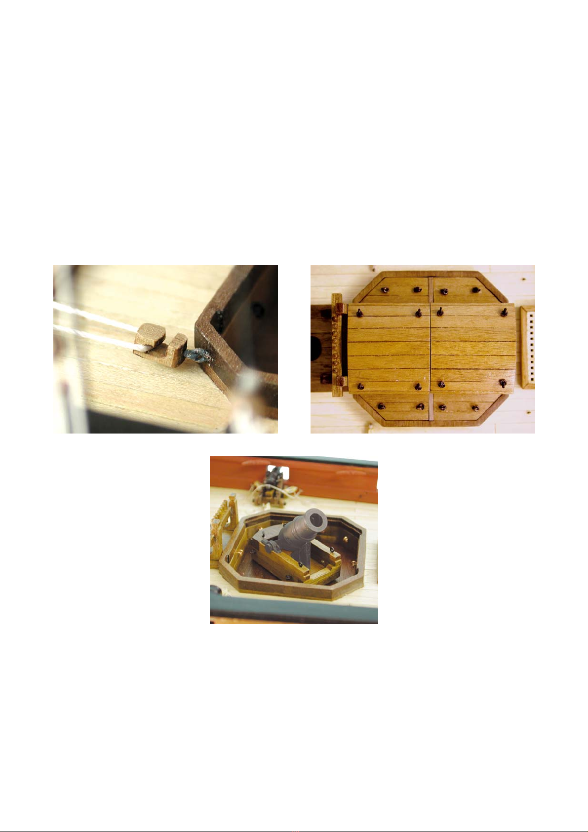
Note: Before gluing the after (10”) mortar housing in position, two 0.65mm holes must be drilled, running fore and aft, into the
forward quarters of the mortar pit surround top, approximately 20mm either side of the centreline and 3.5mm down from the
top face. Into these holes (one each side) glue a copper eyelet, painted matt (metal) black, with the eye running up and down,
ready to accept the messenger snatch block at a later stage of construction as shown (Photo 010).
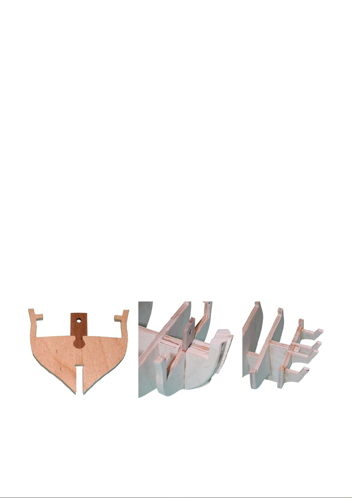
Again using Plan Sheet 2, ‘Mortar housing assemblies’ for reference, identify and remove the lower longitudinal housing
(60), the upper longitudinal housing (61) and the mortar pit traverse bulkhead (62). Clean up the lower longitudinal housing
and dry fit it into the mortar pit surround as shown, taking care that the profiled ‘slot’ faces outboard. To form the removable
strongback, cut a length of 3x3mm walnut approximately 10.75mm long to fit into the slot between the mortar pit surround and
the lower longitudinal housing. Glue a length of 1.5x1.5mm walnut centrally to the top face of this strongback. Make up the
upper longitudinal housing and mortar pit traverse bulkhead assembly as shown, gluing the mortar pit traverse bulkheads in
between the lower longitudinal housings, taking care that the assembly remains square. This assembly now sits over the lower
longitudinal supports, you will notice that at this stage it will not sit down flush against them, to achieve this you must gently
sand the top face of the 1.5x1.5mm walnut of the strongback, do not sand the bottom face of the 3x3mm walnut.
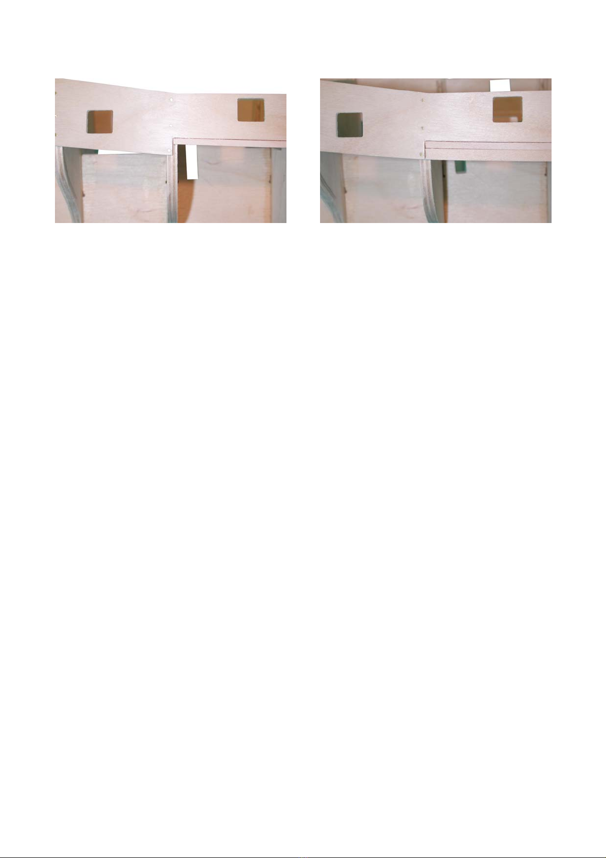
Identify and remove the mortar pit canopy ends, outer and inner, (156 & 157). The canopies are best assembled ‘in situ’ on the
upper longitudinal housing and mortar pit traverse bulkhead assembly; take care, however, not to glue the canopies to this
assembly.
Position the outer canopy ends on the upper longitudinal housing and mortar pit traverse bulkhead assembly, outside the
rabbet, and position the inner canopy ends half way along (approximately 26mm), on top of the rabbet.
Note: The orientation of the profiled slot on the inner canopy ends is unimportant, this simply marks the cut line for the area
beneath to be removed upon completion of the canopy assembly.
Start by gluing the side planks into place, this plank is from 1x5mm walnut, the bottom edge runs flush along the upper
longitudinal housing, outside the rabbet and flush with the lower edge of the outer canopy end, as the inner canopy end is
raised up on the rabbet it will not be flush to this. These side planks will also sit proud of the top edges of both the inner and
outer canopy ends, do not trim this as it will eventually form a flush edge to the top planking. Repeat for the second half of the
canopy. Allow this assembly to dry thoroughly.
The canopy top planking is constructed next from 1x4mm walnut but each plank is reduced and bevelled slightly to an overall
width of approximately 3.5mm. The first plank is laid down the centre line of the canopy, it is an advantage for the aesthetics
of the ship to construct the pair of canopies for each individual mortar housing from one length of 1x4mm walnut, i.e. lay the
central plank to the first half of the canopies and then, continuing with the same length of walnut lay the central plank of the
second half of the canopy. Three further planks will need to be laid either side of these central planks to finish the assembly.
The outer planks can now be bevelled to the camber of the canopy top planking.
Four ringbolts per canopy half (total 16 ringbolts from 32 copper eyelets), constructed as before, must now be secured one into
each corner of each canopy as shown (Photo 011). With the canopies completed, the area below the profiled slot on the inner
canopy end can now be removed by cutting through at the slot and sanding smooth.
The side housing covers are assembled next from 0.5x3mm walnut. Glue three lengths of 0.5x3mm walnut, each 30mm long,
edge to edge forming a ‘sheet’ 30mm by 9mm. Cut out the paper side housing cover template from Plan Sheet 9, ‘Side
housing cover templates’ and lay it over the ‘sheet’ and trim the sheet to size. When done, remove the paper template and
plank one side of the resultant wooden sheet at right angles, i.e. from port to starboard and trim to size. This will result in side
housing covers approximately 1mm thick, repeat this process until you have 4 port and 4 starboard covers. Each housing cover
should now be offered up into position and gently sanded to fit – with the three fore and aft planks to the top. Two ringbolts
must now be secured to the top face of each side cover as shown (Photo 011) (total 16 ringbolts from 32 copper eyelets).
Upon completion of the mortar housings, the whole assembly and component parts should be lightly varnished and can either
be glued together to form a solid structure or left to dry fit as authentic removable components.

©2004 JoTiKa Ltd.
10
The Mortar Beds
The assembly of the 10” mortar bed is identical to that of the 13”, as follows. Identify and remove the mortar bed base (64/68),
timber baulks (65/69), upper baulks (46/47), cheeks (66/70) and transverse piece (67/71). Using Plan Sheet 2, ‘Mortar bed
assemblies’ for reference, assemble the mortar pit bases as shown. Glue the timber baulks to the base, ensuring the sides and
after curved edge all align. The transverse piece can next be positioned onto the base, across the forward face of the timber
baulk. Now glue the upper baulk to the timber baulk, again ensuring the sides and after curved edge all align and with the
profiled curved edge of the upper baulk to the top. The cheeks are now fitted against the forward face of the upper baulk and
the top face of the timber baulk. A length of 2mm dowel, 7mm long can now be located into the hole of the mortar bed, this
simulates the iron spindle to locate the bed into the housing base and allows it to rotate.
Identify the correct mortar, chock and hinged trunnion cap for each bed assembly. Position the mortar into the trunnion slot of
the cheeks, and dry fit the hinged trunnion caps, bending them around the mortar trunnion, noting that the end of the hinged
trunnion cap with a hole through it is positioned to the front. When you are happy with the fit, remembering that you must
allow enough ‘play’ for the mortar to be elevated, secure the hinged trunnion cap into position with superglue. When the glue
has thoroughly dried, drill a hole down into the cheek, through the hole in the hinged trunnion cap, into which a copper eyelet
is to be positioned, with the ring running fore and aft as shown on (Photo 12). Eight more copper eyelets are to be positioned
into the mortar bed as shown on Plan Sheet 9, ‘13” mortar bed eyelet arrangement’ & ‘10” mortar bed eyelet arrangement’.
The chock can either be glued into position against the underside of the mortar as shown on (Photo 12) or left in the mortar
housing to allow the mortar to lie flat.
Note: The mortar, chock, copper eyelets and hinged trunnion cap should all be painted matt (metal) black, the bed itself is
lightly varnished.
The Upper Gun Deck Planking
The upper gun deck is planked with 0.5x4mm maple. The first planks to be laid on the upper gun deck should run fore and aft
along the outboard sides of the mortar housings as shown on Plan Sheet 2, ‘Main deck planking’. This may appear to be
unconventional, but because of the complex shape of the housings, it is the easiest way in which to plank the deck.
Where the planks intersect the locating slots for the curved quarterdeck bulkhead support pillars, these slots should be marked
onto the planking but do not trim the planks at this stage. They are best trimmed off when the curved quarterdeck bulkhead
support pillars are finally positioned, this will allow for any fore and aft or lateral movement required when fitting the
bulkhead. The planking should also run all the way forward to the bows.
Continue to plank the deck outboard to each bulwark. With the outboard deck planked, the central area can now be finished by
working inboard from the first planks laid. Cut, trim and dry fit the planks to ensure they meet accurately at the centre line
drawn on previously. Remember to cut the openings for the masts and hatches etc. as you progress. When the planking is
complete, apply a coat of varnish to seal.
Note: For added authenticity you can lay the planks with a ‘three-butt shift’ as shown on Plan Sheet 2, ‘Main deck planking’,
in this case the planks should either be cut to a length of 130mm or laid full length and the join line, every 130mm, scored into
the plank with a sharp knife (visually, this latter method often looks the most appealing). The end of each subsequent plank
should then be offset from its neighbour by 32.5mm such that the ends of every fourth plank only align.
Inner Bulwark Patterns
Identify and remove the inner bulwark patterns (158) from the 1.5mm walnut sheet. When these bulwark patterns are shaped
for fitting it is vital to realise that the profiled slot towards the after end will be positioned to face inboard as it forms an
integral part of the curved quarterdeck bulkhead assembly.
The inner bulwark pattern should be soaked in water, for a maximum of 30 minutes, and then formed around the gunport
pattern shaper. It should be dealt with in the same manner as the gunport pattern; ensuring one port and one starboard inner
bulwark are formed by turning the gunport pattern shaper over.
When you are happy with the shape of the inner bulwark pattern, it can be dry fitted against the inner face of the gunport
pattern, checking that it fits fairly flush along the decking and that the ports all marry up accurately, some light sanding may be
required (any gaps between the inner bulwark pattern and the deck will be covered by the spirketting at a later stage). The
forward edge of the inner bulwark pattern will also require trimming to allow it to butt up against the plank termination
patterns either side of the upright of the keel. When satisfied with the dry fit, glue it firmly into position using clamps where
possible, all the time checking that the gunport cut outs remain aligned.
Lining the Gunports Without Lids
The second through sixth gunports each side do not have lids. They should now be lined using 1x4mm walnut. Glue the lining
into position, bottom and top first then each side. When the lining has been applied and allowed to dry thoroughly it should be
sanded back flush to both the inner bulwark pattern and the outer gunport pattern. The remaining chase ports and cabin lights
with lids will be lined in a different manner at a later stage of construction.

©2004 JoTiKa Ltd. 11
Completion of the Second Planking
The second planking from the wale up can now be completed with 1x4mm walnut strip. This planking should be done as
before, soaking the planks, but there should be little or no need to taper any of these remaining planks. However, the topmost
plank will need to be trimmed flush to the top of the gunport pattern. Each of the gunports and cabin lights should be cleared as
you progress. The planking over the lined gunports should be trimmed flush with the inner surface of the linings while the
planking over the currently unlined chase ports and cabin lights should be trimmed flush with the openings in the gunport
pattern. It is advisable at this stage to sand the hull smooth, touch up any paint and seal exposed timber with varnish. The stern
post (29) should also now be fitted and painted white below the waterline.
Lining the Gunports With Lids
The chase ports and cabin lights have lids or, in the case of the chase ports, double doors. The way in which these gunports are
lined differs from those gunports without lids. They are lined with 1x4mm walnut strip but this lining must be set back 1mm
from the ships side, refer to Plan Sheet 1, ‘Gunports with lids’. It is of absolute importance that the linings are set back into
the openings by 1mm. The gunport lids themselves have been cut to allow for this and the brass etched hinges have also been
designed likewise. The hinges will be glued into position onto the gunport lid and the ships side as shown on Plan Sheet 1,
‘Attaching gunport lids and hinges’. If the recessing has not been carried out correctly then the hinges will not fit. The lids
themselves will be very delicate when positioned and as such will be fitted at a later stage. With all of the gunports and cabin
lights now lined, they can be painted red ochre, the outboard face of the lining for gunports with lids however, should not be
painted red ochre but left natural and varnished; only the inside faces and inboard edge will be painted red ochre.
Note: The inboard edge of the lining should be sanded flush to the inner bulwark.
Inner Bulwark Spirketting
The spirketting is formed using a length of 1x7mm walnut strip. Dry fit it against the inboard side of the inner bulwark so that
it lies level with the bottom edge of the upper gun deck gunports and flush along the deck (Photo 013). This plank butts up
against the plank termination patterns in the bow (some soaking may be required) (Photo 015) and runs aft in one continuous
length to the profiled slot in the after end of the inner bulwark pattern, which forms part of the quarterdeck bulkhead screen
and should be trimmed to follow this. It is imperative that the spirketting is trimmed accurately to this slot and to achieve this
you may find it of benefit to position a piece of scrap 0.8mm ply into the slot, there should be no gaps between this scrap
material and the spirketting as shown on Plan Sheet 2, ‘Inner bulwark spirketting & sheer rail’.
Photo 013
Photo 014
Photo 015
Photo 016

©2004 JoTiKa Ltd.
12
Inner Bulwark Sheer Rail
The inner bulwark sheer rail is formed using a length of 1x10mm walnut strip. Dry fit the sheer rail against the inboard side of
the inner bulwark (some soaking may be required), you should consider each of the following points when positioning the
sheer rail: (the position of the ‘break of forecastle’ is shown on Plan Sheet 1)
1. The lower edge of the inner bulwark sheer rail should align to the top edge of the second through sixth gunports
and as such should run parallel with the top edge of the spirketting (Photo 013, note the capping, which is fitted
at a later stage, is also shown in this photo).
2. The top edge of the sheer rail should be approximately 2.5mm below the top of the inner bulwark pattern at the
break of the forecastle, as shown on Plan Sheet 2, ‘Inner bulwark spirketting & sheer rail’ and (Photo 014) so
that when the forecastle deck is positioned onto the sheer rail and planked, it is seated 1mm below the top of the
inner bulwark at this point.
3. The sheer rail continues forward and should lie level with the top of the keel and termination patterns at the bows
(Photo 015). The outboard edges of the forecastle deck, when fitted, will sit on this sheer rail and the termination
patterns and will also lie on the bowsprit step.
4. You will notice that from the break of the forecastle to the bows, the sheer rail and spirketting no longer run
parallel and indeed the sheer rail fouls the chase port. This is correct and the chase port should be cleared as
shown (Photo 015). Similarly the lower edge of the sheer rail forward to the plank termination patterns should be
tapered as shown.
5. When the plank has been glued into position and thoroughly dried, the top edge, aft from the break of the
forecastle, should be trimmed and sanded flush with the top edge of the inner bulwark pattern (Photo 015).
6. As with the spirketting, the after edge of the sheer rail should be trimmed precisely to follow the profiled slot in
the after end of the inner bulwark pattern.
7. With the spirketting and sheer rail in place, the whole of the inner bulwark should be painted red ochre.
Upper Gun Deck Gratings, Hatches, Coamings and Spanshackles
Starting from the bows, the first opening to be lined, with 1.5x1.5mm walnut, is for the galley flue. It is situated directly behind
the bowsprit step and when lined, the opening should measure 6mm x 6mm to accept the flue uptake at a later stage.
The fore access hatch is to be lined with 2x3mm walnut and fitted with a grating. The lining should be orientated such that the
lining is 2mm wide and stands 3mm from the deck. Make up a grating set from the grating strips (301) which are to be slotted
together as shown (Fig 001) and, when completed, brush on watered down PVA glue to secure the strips. Once dry, trim and
sand the grating to measure approximately 24mm by 13mm. With the grating made up and trimmed to size, glue the coaming
strips around the outside edge, remembering their correct orientation and ensuring the grating is flush with the top edges of the
coaming. When thoroughly dried, this whole assembly can be glued into position over the locating hole in the deck.
The fish davit span shackles (220) should be identified on the brass etched sheet and painted matt (metal) black. Drill two
0.65mm holes (one each side) into the deck to accept the spanshackles, they should be located approximate 1mm forward of
the fore mortar housing and 29mm from the centreline, using Plan Sheet 2, ‘Main deck layout’ for reference. Bend the
spanshackle over, at the hinge point, to allow it to lie on the deck, and fix into position.
The main hatch, located between the mortar housings is to be lined next with 2x3mm walnut orientated as per the fore access
hatch lining. Locate and identify the main hatch cover (fore) (165) and the main hatch covers (166). Make up the lining, off the
model, which should have overall outside dimensions of 29mm by 29mm, this overall outside measurement will be critical
when laying the deck reinforcement planking shortly, as a result, the overall inside dimensions should be 25mm by 25mm to
accurately fit the main hatch covers. When you are happy with the lining it can be glued into position over its locating hole in
the deck, again it is critical for the laying of the deck reinforcement planking that this lining is glued on centrally and squarely.
With the lining in position, a recessed lip must be made up using 1.5x1.5mm walnut. This lip will provide the support for the
main hatch covers and should be positioned 1.5mm down from the lining top edge so that the covers will sit flush with the top
of the lining when in position.
Note: The fore hatch cover should be positioned to the front of the lining and with the cut out semi-circles forward into the
corners of the lining. The 1.5x1.5mm walnut recess will need to be cleared of the area below these semi-circular cut outs to
allow free passage of the anchor cable when rigged.
All four hatch covers should be fitted with a pair of ringbolts from 16 copper eyelets positioned as shown (Photo 016). The
hatch covers should be varnished and can either be glued into position or dry-fitted as removable components.
Referring to Plan Sheet 2, ‘Main hatch & deck reinforcement’, the deck reinforcement planking can now be laid between the
main hatch lining and the forward mortar housing using 2x5mm walnut and 2x4mm walnut. Cut one length of 2x5mm walnut
to fit between the main hatch lining and the forward mortar housing. This plank can then be laid down the centre line.
Remembering to clear the mast hole as you progress, six planks (three each side) of 2x4mm walnut should also be laid. When
these planks have all been laid their outer edge should form a continuous run with the outer edges of the main hatch lining, i.e.
an overall width of 29mm.

©2004 JoTiKa Ltd. 13
Fig 001
Fitting the Forecastle
Note: If you are intending to fit a pair of 4pdr cannons at the chase ports they will need to be assembled, fitted and rigged prior
to the fitting of the forecastle as access will be very limited once the forecastle is in place. Instructions for the assembly and
fitting of the 4pdr cannons can be found on pages 19 & 20 (Photo 017).
Identify and remove the forecastle aft support beam (25) from the 5mm walnut sheet and the forecastle deck (197) from the
0.8mm ply sheet.
Offer the forecastle deck into position and trim it to fit as necessary (dry fitting only at this stage) with the following
consideration in mind, it will be of benefit to identify, with a mark, the top and bottom faces on the deck:
1. The 6mm by 6mm cut out in the deck must be located directly and squarely above the 6mm by 6mm galley flue
opening in the upper gun deck beneath.
2. The forecastle will sit onto the ‘lip’ created by the inner bulwark sheer rail, and across the top of the bowsprit
step.
3. The camber which will be created by the bowsprit step and the forecastle aft support beam, when fitted, must be
adhered to.
When you are happy with the fit of the forecastle and with it dry fitted in place, gently mark onto the inner bulwarks of the hull
the position of the aft edge of the forecastle. The forecastle should now be removed and the underside of the 6mm by 6mm
opening for the galley flue can be lined with 1.5x1.5mm walnut, however, only the forward and side edges should be lined, do
not line the after edge as it will foul the forecastle aft support beam when fitted.
The forecastle aft support beam should now be offered into position on the hull, at the position of the after edge of the
forecastle previously marked onto the inner bulwark. The outside edges of the support beam should be trimmed to dry fit
neatly flush against the inner bulwark at this point (Photo 017).
When you are happy with the fit of both the forecastle deck and the aft support beam, they should be glued into position
together, with the support beam located under the forecastle deck and flush with the after edge (Photo 018).
The galley flue between the upper gun deck and the forecastle can now be fitted (Photo 018). The flue is cut from a length of
6x6mm walnut and painted matt (metal) black. It is glued into position down through the hole in the forecastle, into the hole in
the upper gun deck. When fitted and thoroughly dried, it should be sanded flush to the forecastle ply deck.
Photo 017
Photo 018

©2004 JoTiKa Ltd.
14
Planking the Forecastle
The forecastle is planked with 0.5x4mm maple. Mark the centreline down the forecastle and, referring to Plan Sheet 2,
‘Forecastle deck planking’, plank either side of this line outwards to the bulwarks, clearing the bowsprit opening and galley
flue opening as you progress. Also, using a length of 8mm dowel for reference, you must file out a notch in the bulwarks to
accept the bowsprit, noting that nothing should be removed from the stem itself as this forms the locating angle and support for
the bowsprit (Photo 17 & Photo 18).
The upper face of the 6mm by 6mm galley flue opening can now be lined (all four sides) with 1.5x1.5mm walnut, and the
whole deck varnished to seal.
The exposed area of the forecastle bulwarks, from the break of the forecastle around to the stem, should now be planked with
1x4mm walnut and painted red ochre (Photo 018).
Note: Unlike the main deck, there is no planking offset on the forecastle as the planks are sufficiently long to run the full
length of the deck.
The Stern Fascia and Stern Counter
Identify the stern fascia (167) and stern counter (168) from the 1.5mm walnut sheet. Referring to (Fig 002), temporarily pin the
stern fascia across the stern extensions, there are several points of reference to note when doing this as follows:
1. The top edge of the fascia should be positioned approximately 1mm down from the top rearmost edge of the
bulwarks. This will allow for the taffrail capping to be fitted at a later stage.
2. The inner most fascia window openings should have their edges equally spaced between the inner stern
extensions.
3. The top edge of the lower projections, either side of the fascia, should be level with the top plank of the wale, The
outer edge, slightly in from the projections, should be trimmed flush to the hull sides.
At this stage consideration should be given to the way in which you will glaze the windows. It can either be done at a later
stage when fitting the brass etched window frames by cutting 5 individual pieces to fit into the recessed frame or it can be done
at this stage by securing one continuous length across the inside face of the stern fascia. In either case, PVA should be used to
prevent discoloration.
When you are satisfied with the dry fit of the stern fascia, it can be glued into position; if any pins are used during this stage
you must ensure that they do not distort the natural curve of the stern fascia across the stern extensions. The fascia should not
be painted until the stern decoration is fitted at a later stage.
After soaking in water for a maximum of 30 minutes, offer the stern counter (168) into position. The primary fixing position
to note will be the central opening for the rudder. The counter is slightly oversized to allow for variances in hull planking and
some sanding may be required. The counter should be bevelled top and bottom to allow it to ‘feather’ into the stern fascia
above and the lower planking under bulkhead 10 below. Great care should be exercised with the counter during this procedure,
particularly at its centre point.
The counter can now be planked athwartships using 1x4mm walnut strip, again the top and bottom planks should be bevelled
to ‘feather’ in. The planks should also be sanded to maintain the convex shape as necessary (Photo 019).
Two vents should be scored into the counter, one either side of the rudder as shown (Fig 002). They measure 8.5mm wide by
7.5mm high. The brass etched vent hinges (239) can now be glued into position together with the four (two per vent) brass
etched ring bolts (210). The Stern counter should be painted dull black and the brass etched components should be painted matt
(metal) black. Two pairs of ‘dummy’ tackles can now be rigged of 0.1mm natural thread, from the brass etched ring bolts into
a 0.5mm hole drilled through the counter above the vent.
Photo 019

©2004 JoTiKa Ltd. 15
Fig 002
Position of stern extension patterns behind fascia in relation to the window frames.
Area to be sanded Area to be sanded
flush to outer hull. flush to outer hull.
Positioning of the stern vents (8.5mm wide by 7.5mm high) to be scored into the planking of the stern counter.
Note also the positioning and orientation of the hinges (239) and the 0.5mm hole drilled above the hinges for the
Rigging of the stern vent tackles.

©2004 JoTiKa Ltd.
16
The Quarterdeck Bulkhead
The quarterdeck bulkhead assembly is vitally important to the overall aesthetics of the model and as such you should take your
time, read this entire section carefully before progressing and check, re-check and check again all measurements before cutting
anything, particularly the bulkhead panels. The slots in the curved pillars are only 0.75mm deep and 1mm wide so any errors in
the shaping of the bulkhead panels will show. All components should be dry fitted only until you are confident of their
positioning relative to the surrounding components.
Each of the curved pillars are identical and can be used in any position.
Identify and remove the curved pillars (159) from the 1.5mm walnut sheet. Also, identify and remove the false bulkhead (15)
from the 5mm ply sheet. This bulkhead will fit into position across the keel and behind bulkhead seven, butting up against the
keel upright at this position as shown on Plan Sheet 1.
Glue together the pairs of curved pillars, to form 6 complete curved pillars. Ensure that the grooves face outboard to accept the
bulkhead panels at a later stage and that once glued together, the pairs are perfectly aligned to one another with no lips. If there
are any overlaps, ‘lips’, it will be impossible to fit the screens into position in a straight line between the bulwarks.
Temporarily fix the false bulkhead into position, you should support this bulkhead to ensure that it remains square across the
hull and that the outer edges are equidistant to the inner bulwarks. Dry fit the curved pillars between this false bulkhead and
bulkhead seven, the deck planking will need to be trimmed to fit to the curved pillars at this stage. Take care that each pillar is
running parallel to its neighbouring pillars and that they are all parallel to the keel, fore and aft, and that they are all vertical.
Any alteration required to do this should only be done by gently manipulating the orientation of the false bulkhead, no
trimming or shaping is required.
When you are happy with the fit and the trimming of the deck planking, identify and remove the two outer screen panels (205)
from the 0.8mm ply sheet. This phase of construction will require the removal of the outermost curved pillars. With the curved
pillars removed, the outer edges of the screen panels should be cut to fit against the inner bulwark when positioned in the pre-
profiled groove. You should continue to remove material from the outside edge until it is possible to re-position the outer
curved pillars, by sliding the groove in the curved pillar down over the inner edge of the outer screen, the lower edge of the
screen should also fit flush against the deck planking.
When you are satisfied with the fit of the outer screens, the remaining screen panels (202-204) can be identified, removed from
the 0.8mm ply sheet and fitted into their respective curved pillar slots. Light sanding may be required until a perfect fit is
attained.
Note: No components have been permanently fitted at this stage.
When you are happy with the fit of each component, the centre (202), second (203) and third (204) screen panels can be
removed and put to one side (after marking each one to ensure it can be re-fitted in the correct slot at a later stage). This will
leave just the outer screens, the curved pillars and the false bulkhead dry fitted in place.
Remove the outer curved pillars and the outer screens and paint the forward face of the outer screen French blue. When the
painting has been completed and allowed to dry thoroughly, the outer screens can be re-positioned along with the outer curved
pillars. After checking for fit again, all of the curved pillars, the false bulkhead and the outer screens only can be finally fitted
and glued into position. With the assembly thoroughly dry, a length of 0.5x3mm walnut should be glued to the front edge of
each pillar, from flush to the deck to flush with the top edge. When the whole assembly has dried thoroughly, carefully sand
off any high spots along the top edges to allow the ply quarterdeck, when fitted at a later stage, to sit flush on top of the
assembly, while retaining the in-built camber (Photo 020, note that the screens are only temporarily fitted in this photo).
Note: The curved pillars are not painted but will be varnished to seal, bear in mind that after varnishing, the fit of each screen
may need to be re-confirmed.
The decoration of the remaining bulkhead screens (203, 204 & 205) is applied next. After much testing, a very specific method
of fitting the decals (289) has been found that will show off the decoration, as if it were hand painted, and eliminate any sheen
reflection usually associated with decals. This is done as follows:
1. Start by painting the five remaining screens French blue, sand and repeat until a smooth surface is attained.
2. The decals should now be cut out oversized, the curved line marked on the bottom of each decal denotes the
bottom edge of the screen and should be adhered to by trimming the bottom edge until the line itself has just been
removed.
3. Each decal should now be dry fitted, do not remove the backing, against its corresponding screen panel (Photo
021), aligning the bottom edge of the decal to the bottom edge of the screen. With these edges aligned, the sides
and top of the decal should be trimmed to precisely fit the screen.
4. The back of the decal has a tacky film to it (once the backing has been removed). With the backing removed, the
back of the decal should also be painted French blue, directly onto the tacky film. Coat as required to achieve an
even covering.
5. When both screen and decal paints are thoroughly dried, the decal is glued to the screen with PVA.
The four hinges of the cabin doors (237) can also now be painted matt (metal) black and glued to the corresponding screen as
shown on Plan Sheet 9, ‘Section through bulkhead 7’, using PVA glue. With the screens completed they can each be secured
into place in the curved pillars, again using PVA brushed onto the after face and pillar supports when in position (Photo 021).
Note: PVA glue only should be used; super glue / cyanoacrylate will cause discoloration of the decals.

©2004 JoTiKa Ltd. 17
Photo 020
Photo 021
Fitting the Quarterdeck
Identify and remove the quarterdeck (196) from the 0.8mm ply sheet.
Remove the bulkhead uprights (bulkheads 8 – 10), and the uprights of the stern extensions and sand them flush. Offer the
quarterdeck into position such that the forward edge is flush with the 0.5x3mm walnut overlay on the front face of the curved
pillars. Trim as necessary to achieve a good fit, ensuring that the locating hole for the rudder head is central between the two
inner stern extensions. With a good fit achieved, the quarterdeck can be glued into position.
The Quarterdeck Planking
The quarterdeck is planked with 0.5x4mm maple. Mark the centreline down the quarterdeck and, referring to Plan Sheet 2,
‘Quarterdeck planking’, plank either side of this line outwards to the bulwarks, clearing the companionway and rudder head
opening as you progress. Upon completion a grating measuring 12mm by 12mm should be made up and lined with 2x2mm
walnut strip and the assembly should be glued into position over its locating hole in the quarterdeck, when in position you will
notice the grating sits down into the locating hole onto the keel, as a result the grating may require some sanding to allow the
coaming to sit flush on the deck. Upon completion, seal the whole quarterdeck with varnish.
Note: Unlike the main deck, there is no planking offset on the quarterdeck as the planks are sufficiently long to run the full
length of the deck.
The Quarterdeck Bulwarks
Using a piece of scrap 1.5mm walnut ply, cut out the shape of the bulwarks above the quarterdeck and glue into position. The
bulwark should then be planked with 1x4mm walnut strip. Remove any excess from the top edge of the bulwark, back to the
shape of the gunport pattern and the bulwark should then be painted red ochre.

©2004 JoTiKa Ltd.
18
The Capping Rails
Identify the main capping rail (108) and the forecastle capping rail (107) and remove them from the 2mm walnut sheet, also,
identify and remove the capping step (forecastle to main) (32) from the 5mm walnut sheet. Referring to Plan Sheet 2
temporarily, but securely, fix the main capping into place with the following considerations:
1. The front end of the main capping is bevelled slightly to lead into the break of the forecastle. Any excess length is
to be removed from the after end.
2. The main capping is wider than required to allow for any deviation during the building process, however, the
inner edge of the capping should be aligned to the inner face of the bulwarks, and excess should be removed from
the outboard face of the capping only. This will ensure the cut outs in the after part of the capping are centrally
aligned and that the pinrail appears flush to the bulwark.
3. Check across the hull to ensure that the pinrails and the cut outs in the after part of each capping (port and
starboard) are aligned to those opposite.
Again using Plan Sheet 2 for reference, the forecastle capping can also now be temporarily but securely fitted with the
following considerations:
1. With a length of 8mm dowel in position, to simulate the bowsprit, the capping should be positioned flush against
this at the stem. Check also that when viewed from above the capping rails align at the bowsprit as if to form a
continuous run.
2. The largest cut out in the capping, for the knightheads should be positioned towards the stem.
3. All of the cut outs should be positioned centrally along the top of the bulwark. Unlike the main capping, both
inboard and outboard edges of the forecastle capping will overhang the bulwark.
With the forecastle and main capping securely but still temporarily positioned, you should begin reducing the ‘overhanging’
edges back to be flush with the inner bulwark and outer hull sides. At this stage it is recommended that the inner face be
sanded as flush as possible to the inner bulwark while the outer face should be roughly sanded flush as final sanding of the
outboard face can be done after the capping rails have been permanently secured in place.
When you are happy with the fit of the inboard edges, the capping rails should be removed from the hull and this inboard edge
should be painted dull black. When thoroughly dry, re-fit the capping rails permanently with glue back into the positions they
were removed from.
The capping step can now be fitted at the break of the forecastle. It should be positioned flush against the top of the bulwark,
with no gaps, and the main capping. The forward edge will need to be reduced to run into the forecastle capping, again with no
gaps and both the inboard and outboard faces sanded flush and the inboard face painted dull black.
With the capping rails firmly fixed in position, the outboard edges can now be sanded flush to the hull sides. The top and
outboard faces of the forecastle capping and step can now be painted dull black. The top and outboard faces of the main
capping will also be painted dull black but only after fitting of the brass rail (sheer rail).
Identify, remove from the 4mm walnut sheet and paint dull black the fish davit cleats (49). These can now be glued into
position on the main capping, directly aft of the forecastle capping step as shown on Plan Sheet 1, ‘Hull detail’.
The Sheer Rail
The sheer rails are formed from the two 500mm lengths of brass extrusion (282) profile 1 (Photo 022), one each side. They are
fitted as follows:
1. Before working with the brass extrusion on the model it is advisable to wash the extrusion in warm soapy water
to remove any oils that may otherwise discolour the wood and hinder both painting and adhesion.
2. You should start at the bow. To obtain roughly the correct shape at the bow you can once again use the gunport
pattern shaper as a template. You will find the brass much easier to work with when warmed, do not use an
intense heat as this will deform the detailed shape of the rail or even melt the rail completely.
3. You will need to bevel the front edge to sit flush against the stem.
4. The rail should run parallel to the forecastle capping around the bow, and should remain flush to the top edge of
the main capping from the break of the forecastle all the way to the transom as shown on Plan Sheet 1, ‘Hull
detail’.
5. When you are happy with the shape and fit of the rail, it can be glued into position, you should roughen the back
face of the rail with rough sandpaper to ensure a good contact. The rail should be painted dull black either before
positioning on the model or after positioning having masked off the hull.
6. The area between the sheer rail and the forecastle capping rail should now be painted French blue.
7. If not done previously, the top of the main capping rail can now be painted dull black.

©2004 JoTiKa Ltd. 19
Photo 022
Main Deck Inner Bulwark Fittings
Using Plan Sheet 2, ‘Main deck layout’ & ‘Main deck inner bulwark fittings’ for reference, fit the inner bulwark cleats (259
& 260), kevels (118), timberheads fore (37) and timberheads aft (36), remembering to drill all sheave holes as shown prior to
fitting.
Main Deck Guns and Carriages
Identify the 4pdr turned brass cannon barrel (277) (Photo 023).
When completed, the gun carriage should be left natural and varnished to seal. The axle stubs, barrel and other ironwork
should be painted matt (metal) black.
Identify the gun carriage components; carriage sides (160), rear axle (161), front axle (162), rear wheel (101), front wheel
(100) and quoin (76).
Make up all of the gun carriage assemblies as shown on the Plan Sheet 9, ‘4pdr cannon carriage eyelet arrangement’. The
shorter wheel axle is located at the front to give the carriage a taper when viewed from above.
Note: Do not fit the wheels until the carriage has been assembled.
The larger wheels fit on the front of the carriage to compensate for the deck camber. The wheels themselves are simply
varnished, not painted.
Cut a bed bolt for each carriage from the 1mm brass wire (321), painted matt (metal) black, and glue into place. Glue the stool
bed into place, but do not glue the quoin to the stool bed until the cannon is rigged into position, to ensure correct elevation of
the cannon.
Note: The stool beds are positioned approximately 1mm forward of the rear of the carriage sides, the stool beds are 0.5x3mm
walnut.
Mark the eyelet positions on each carriage and drill with a 0.5mm drill. There is also an eyelet at the centre of the rear and
front axles. Cut the stems of the brass eyelets (210) from their brass etch sheet leaving 2mm for gluing into the carriage and
glue in place.
When completed, varnish the carriages as previously described. Carefully push the wheels onto the axles.
Cannon trunnions are cut from 1.5mm brass wire and should be long enough to reach the outer wall of the carriage sides. Glue
in place through the cannon trunnion hole and position on the carriage.
Note: Check the cannon orientation beforehand, the trunnion hole is drilled slightly off centre and should be nearer the bottom
of the barrel when in place (Photo 023).
All cannons should be painted matt (metal) black.
Cut out the trunnion brackets (234) from their brass etched sheet. Fit by bending the thinned centre of the bracket around the
trunnion, carefully drill down through the holes in the bracket, with a 0.7mm drill, into the carriage sides. Fix in place with the
dome head pins (284), these can be cut short before fixing. Paint the trunnion brackets and pins matt (metal) black.
Note: The cannon trunnion is not glued to the carriage or the trunnion bracket, it should be free to allow the cannon to be
raised or lowered with the quoin when fitted.
Table of contents
Other Jotika Toy manuals