Joy-it JT-DPM8605 User manual

Published: 05.06.2020
JT-DPM8605
Programmable lab power supply
The JT-DPM8624 is a programmable
Buck power supply. It has both a con-
stant voltage and a constant current
mode. With its TTL interface, it is pos-
sible to manage any setting comforta-
bly via your PC with a free soware.
As optional equipment for this power
supply, a wireless control panel is
available, which enables remote con-
trol of up to 10 meter (without obsta-
cle) to any setting and data.
MAIN FEATURES
Interface TTL
Voltage supply 10 - 75 V DC
Voltage output 0 - 60 V DC
Current output 0 – 5 A
Power output 0 - 300 W
Voltage resolution 10 mV
Current resolution 1 mA
Output ripple < 50 mVpp
Response time < 50 ms
Size 131 x 112 x 55 mm
Items delivered JT-DPM8605
FURTHER SPECIFICATIONS
Voltage display accuracy 10 mV
Current display accuracy 1 mA
Voltage fault tolerance 0,2 % + 1 digit
Current fault tolerance 0,5 % + 1 digit
Operating temperature -10°C - 45°C

JT-DPM8600
Programmable lab power supplies
2. GENERAL INFORMATION
Dear customer,
thank you for choosing our product. In the following, we will show you how
to use your product.
Should you encounter any unexpected problems during use, please do not
hesitate to contact us.
1. SAFETY INSTRUCTIONS
Our product is suitable for up to 75 Volt DC. Working with voltage
over 60 V DC is re-served for trained electricians, because of the
hazard of an electric shock which may cause serious injuries or
death. Non-electricians have to use a voltage source below 60
Volt DC. !

Model
3. TECHNICAL PARAMETERS
The DPM8600 series are programmable power supplies which have a large
output power, are compact and are well structured. At the same time, it is
equipped with TTL serial communication interface or RS485 communication
interface, which provides a serial communication protocol.
It can also be applied to modbus-RTU communication protocol and supports
further development from users. Moreover, it can provide multi-purpose
solution according to your design and testing requirements.
Also, DPM8600 series can be equipped with a wireless remote control. The
wireless controller adopts 2.4-inch LCD screen. It has many display values,
a simple operation, a built-in lithium battery which can be recharged and it
can control the power supply from up to 10 meters wirelessly. The wireless
controller can control multiple power supplies simultaneously.
This modular power supply can be applied in several aspects. It can be used
for example as an ammeter, a smartmeter, a LED driver, a voltage regulator
for solar panels or in an industrial control.
If the device is damaged or the scope of delivery incomplete, do not use it
and contact our support. Otherwise, if the device is damaged, it could cause
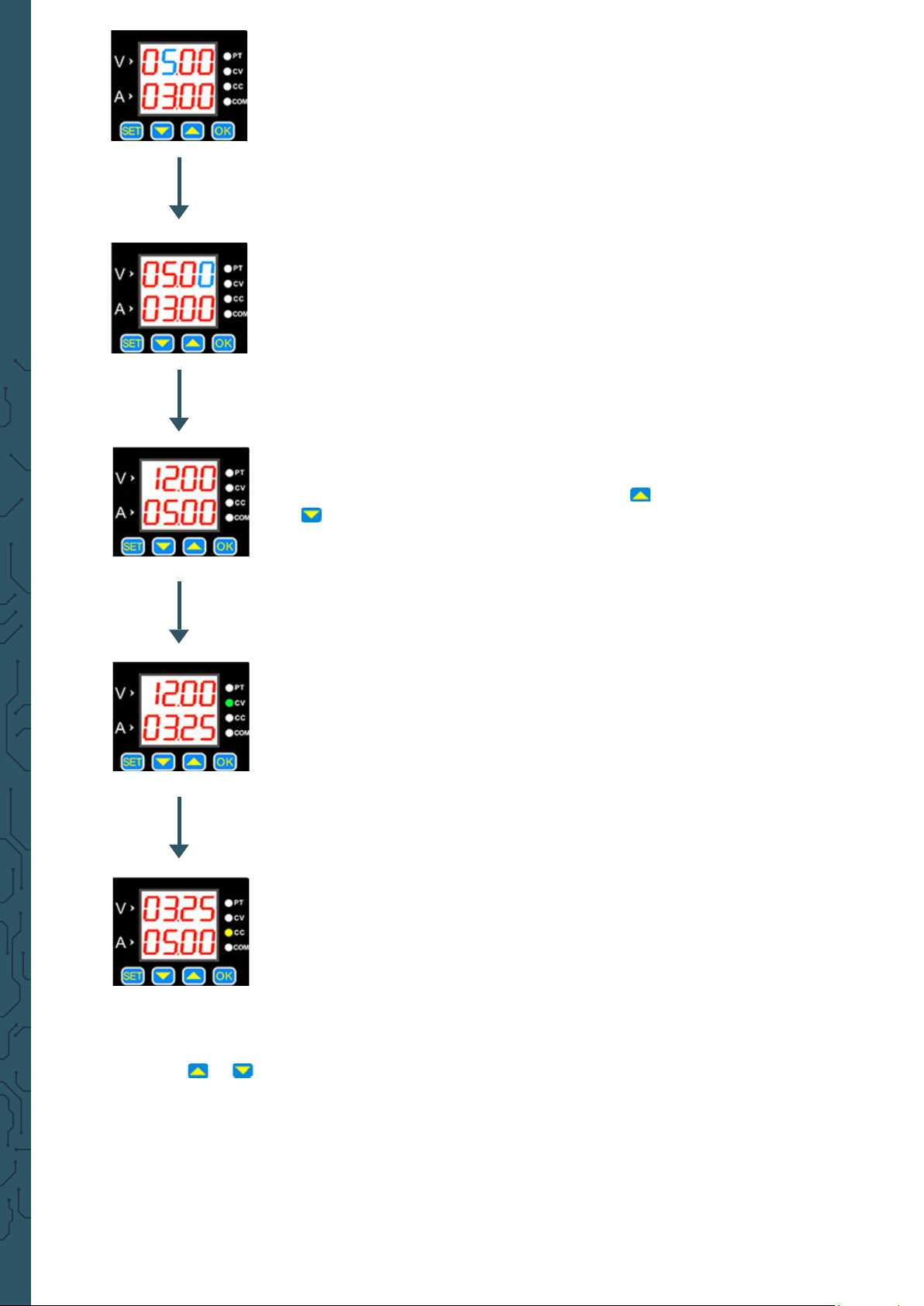
NOTE: The following description uses the DPM8624 as an example.
The DPM8605 works similar to the DPM8624.
DPM-8605 DPM8624-485
Input voltage 10 - 75 V 10 - 75 V
Output voltage 0 - 60 V 0 - 60 V
Output current 0 - 5 A 0 - 24 A
Output power 0 - 300 W 0 - 1440 W
Communication
interface
DPM-8605 TTl serial communication interface
DPM8624-485 RS-485 communictaion interface
Voltage resolution 10 mV
Current resolution 1 mA 10 mA
Output ripple < 50 mVpp
92 %
Display accuracy 10 mV, 1 mA 10 mV, 1 mA
Output tolerance voltage: ± 2 %/ current: ± 5 %
Response time < 50 ms
Dimension 120 · 131 · 55 mm 150 · 120 · 59 mm
Applied ambient
temperature -25 - 60 °C

4. MODULE
5. DISPLAY
Power Switch
Negative input
Positive input
LED digital tube
Fan
Working status
indicator
Positive output
Negative output
Communication
interface
Function
buttons
05.00
03.00
I-SA
_10_
I-SA
_11_
I-SA
_12_
2-dF
__N_
2-dF
__Y_
3-ON
__0_
3-ON
__1_
4-Fd
__0_
4-Fd
__1_
5-CS
__0_
5-CS
__1_
6-bd
0096
7-Ad
_01_
8-CH
_01_
-Ld-
__0_
-SA-
__0_
Corr
-°C-
0280
shows voltage values
shows current values
Sets upper limit of voltage and current
Activates quick response
Sets lower limit of voltage and current
Cancels the limits of voltage and current
No factory settings
Sets device to factory settings
activating it
Deactivates quick response
Simple communication
Communication with modbus
Possible to select 2.4, 4.8, 9.6, 19.2, 38.4,
57.6, 115.2 (Kbps) as the baud
99 communication addresses
31 communication channels from 00 to 30
(00 means no connection)
Calls parameter from a storage location
0 - 9
Saves parameters to storage location
Calibrate voltage and current
Displays temperature of the device

Constant voltage indicator
The CV indicator light indicates constant voltage
output.
6. INDICATOR
PT
Overheat protection indicator
If the temperature is greater than 80 °C, the light
is activated to indicate the overheat protection.
CV
Constant current indicator
The CC indicator light indicates constant current
output.
CC
Communication indicator
The COM-LED will light up if the device is
communicating.
COM
7. SETUP
First, you have to connect the input and the output correctly to ensure that
the input voltage is high enough for operation. A reverse polarity can cause
damage to the device.
NOTE: The input voltage must be higher than the output voltage by
more than 0.5 V.
The “V“ on the digital tube display shows the voltage and “A“ the current.
The LCD displays the voltage with 2 decimal digits (00.00) and the
activate the device. Then the CV or the CC lights up to indicate that the is
active.
In the following is explained in detail how to set the voltage and current
value:
The default is 5 Volt and 3 Ampere.

Press “SET“ that this value lights up.
If you press this button again the selected digit will
move one further.
The value can be changed with the buttons and
.
current is below the set current, the output is a cons-
tant voltage. The CV light comes on.
If the load current reaches the set current, the out-
put is at the same level as the set current and cons-
tant current. Then the CC light comes on.
Press the or to enter the save and load menu as well as the tempe-
rature display and calibration menu.

Press to return to the menu. To
calibrate the device press . In the
following is the function of the calibration
explained.
can be selected with and . With
Press to exit the temperature display.
Calibration
1. If the set voltage is higher than 20 V, the output is switched on and
there is no load connected, the output current can be calibrated to
zero with the function “Corr.“.
For example if you set 25 V as the output voltage, the zero calibration
for the voltage is still by 25 V.
points of voltage and current are set.
3. If you short-circuit the enabled output and the maximal output current
For example if you set the output current to 3 A, then you calibrate the
output to 3 A.

Temperature display
The temperature display shows the temperature of the device which is con-
trolled by the fan speed and overheat protection. If the temperature is higher
than 40°C then the fan starts working. With each 5 °C the fan speed increases
by one level. If the temperature reaches 60 °C, the fan is at its maximal speed.
SET menu
Press the SET button long , then you enter the SET menu. With pressing the
SET button you switch between each menu point. You can change every value
in this menu by pressing and
settings.
This menu point declares the limit of voltage as well as cur-
rent. The “10“ means the upper limit, “11“ the lower limit
and “12“ the cancelation of the limits.
In this menu point, you can reset your device to the factory
settings with “Y“ you reset the device and with “N“ you stay
with your settings.
This menu point is the status interface. It accomplishes that
when the power supply starts it can start automatically the
output or you must turn it on manually. The “0“ means the
function is deactivated and “1“ means it is activated.

This menu point declares the response time of the interface
when it is decharging. In that case “0“ means slow and “1“
fast.
This menu point declares the communication protrocol.
Here the “0“ is for the simple communication protocol and
“1“ for the modbus communication protocol.
In this menu point you can enter the baud rates. There are
In this menu point you can enter the local addresses. There
are 99 communication addresses.
Upper and lower limits of voltage and current
These limits can be adjusted in the SET menu. For example you set 30 V and
5 A in the main interface. If you now activate the upper limit, you can not
adjust the voltage and the current over the 30 V and the 5 A anymore. Only
lower values are now possible to choose for example 20 V and 4.5 A. The lower
limit works the same way in reverse. You can adjust the voltage and the
current only higher then the chosen values. If you set both limits, the device
can only be in operation in the range from lower limit to upper limit.

Communication protocol
There are two options for the communication protocol the simple and the
Modbus communication. These can be selected in the SET menu.
The simple communication protocol is our custom communication proto-
col which is easy to undestand.
The Modbus communication protocol is the standard Modbus communica-
tion protocol.
Quick response
adjust the voltage lower than before. For example the output voltage is set
on 30 V and you adjust it down to 5 V directly. If the quick response is not
operating, it takes 5 seconds to reduce the voltage from 30 V to 5 V. If it is
active, it takes less than 1 second to reduce the same amount.
Power-on default status
device. If this function is activated and the device goes into operation, the
output automatically starts without any adjustments. If the function is
on manually.
Key lock
If you press long on the OK button , then you activate the key lock. If you
press it long again, it will reverse it again.
8. SOFTWARE
www.joy-it.de
or rather a RS485 adapter.
In doing so, it is to note that in case of an inaccurate connection, the
communication can not be guaranteed between the computer and the lab
power supply.

the chart, the device can be connected with the PC via USB. In the de-
vice-manager in point “connections (COM & LPT)“, the port of the power
suppy can be found. In this case, it is COM4.
You can open now the program.
Attention! You must open the program “8608en“ if you use the DPM8605
and the “8024en“ if you use the DPM8624.
V not connected
ARX (white)
BTX (green)
GND GND (black)
DPM TTL RS485
not connected
A
B
not connected
In the program, you must select the port of the power sup-
ply and click on “Connect“ to connect the power supply
with the computer.
The baudrate is set on 9600 by default and can be set if
necessary on the set value from the device.

If the “Connect“ - button glows green, the device is connected with your
PC. The further operation is as follows:
port
selection
baud-
rate
communication
address
Connect
- button status
display type of
device
end program
dislay of
temperature
data group ...
... load
... save
activate / deactivate
output
output
voltage
output current
set lower
limit
set upper
limit
adjust output
current
adjust
ouput
voltage
The output is deactivated if the button glows red. It will be green as soon as
the output is activated.
refresh-button
for temperature
This manual suits for next models
3
Table of contents
Other Joy-it Power Supply manuals

Joy-it
Joy-it DPS5015 User manual

Joy-it
Joy-it DPS5005 User manual

Joy-it
Joy-it JT-DPM8600 User manual

Joy-it
Joy-it JT-RD6006 User manual

Joy-it
Joy-it JT-RD6006 User manual

Joy-it
Joy-it JT-DPH5005 User manual

Joy-it
Joy-it PS1440 Series User manual

Joy-it
Joy-it JT-RD6006 User manual

Joy-it
Joy-it JT-RD6006-Case02 User manual

Joy-it
Joy-it JT-RD6012-C User manual