Set-Up
Step 1: Unhook the tail rotor linkage from your rudder servo and swing the
servo arm out of the way. Lightly grasp the tail rotor pushrod at the servo end and
run the tail rotor through its entire pitch range. The tail rotor linkage should move
through its entire range smoothly with very little friction and no rough spots. Work
on the linkage system until this is achieved.
Step 2: On your transmitter, set all rudder trimmers (sub-trim, trim offset,
mechanical trim, etc.) to zero. Set the throttle/pitch stick at exactly the hover posi-
tion (standard hover position is 50%). Turn off or zero out both the revolution mix-
ing up and down and the acceleration mixing.
Step 3: Turn on your receiver and allow the helicopter to remain totally
motionless for 3 seconds. This procedure is necessary to allow the G400 time to
establish and record the center or neutral positions.
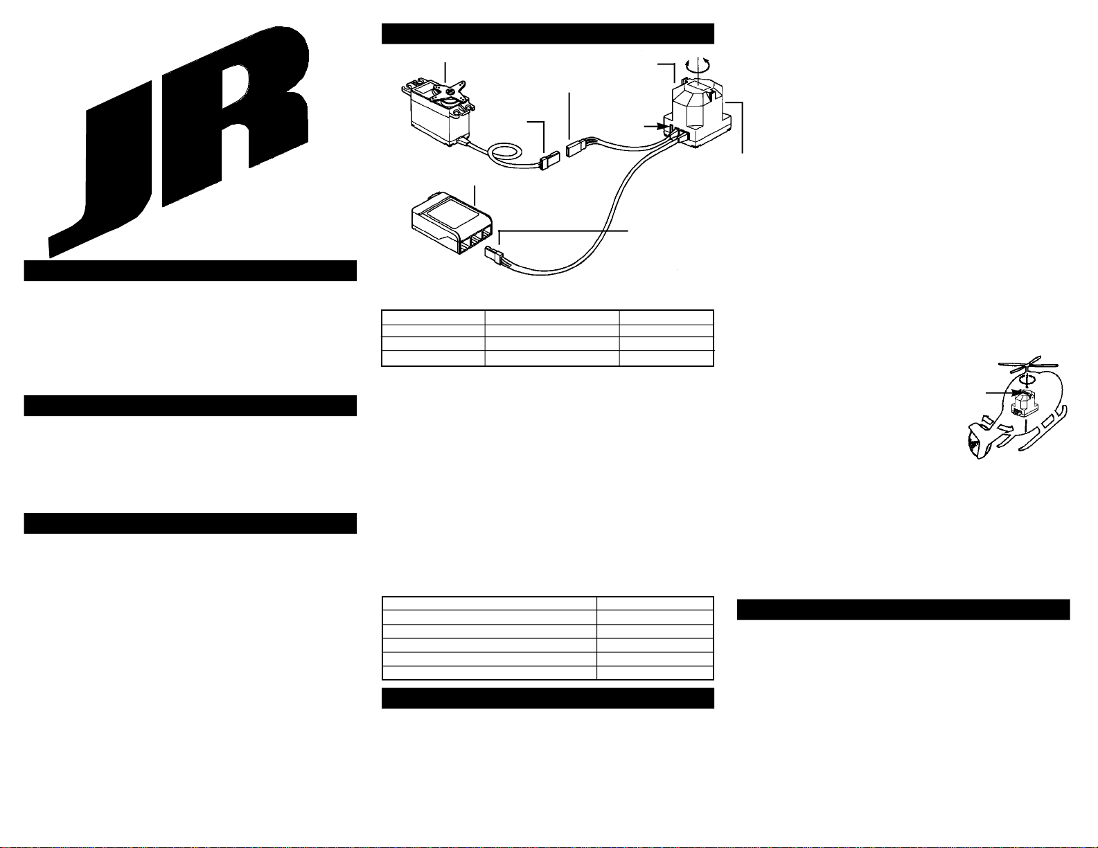
Step 4: Remove
the servo arm and
replace it so that it is
exactly 90 degrees to
the tail rotor pushrod
(see diagram). You may
find that the splines in
the screw output shaft
are just offset enough
on your servo arm so as to
not allow 90 degree posi-
tioning. Rotate the servo
arm to another arm and try again. Find the arm that is closest to 90 degrees and
secure it in place with the provided screw.
Control Rod Ball Placement
For best performance, attach the tail control rod ball to the servo arm at a dis-
tance of approximately 16–18mm from the center mounting screw of the servo
arm. The performance of the G400 will be greatly reduced if the tail control rod ball
is attached at a distance of less than 16mm, as this position will not make full use
of the G400’s sensing abilities.
Step 5: Be sure the rudder servo is moving in the proper direction. A right
servo command should move the nose to the right (if you’re unsure, seek help
from someone more experienced). Reverse the servo direction in the transmitter if
necessary.
Step 6: Give a right rudder command and note the direction the rudder servo
moves (clockwise or counterclockwise). Now pick up the helicopter and quickly
move the nose to the left. The servo should move in
the same direction. If it moves in the opposite direc-
tion, switch the small reverse switch located on the
gyro sensor/amplifier in the opposite direction.
Step 7: To verify that the G400 is compensating
in the correct direction, please refer to the diagram at
right for clarification:
With a quick motion, rotate the nose of the heli-
copter to the left while viewing the servo arm/tail
rotor blades. If correct, the leading edge (front) of
the tail rotor blades should pitch to the left as
shown. Reverse the direction of the gyro compensa-
tion if necessary using the Direction Reversing
Switch located on the Sensor/Amplifier Unit.
Overdriving the Tail Rotor
As illustrated above, the transmitter gives a command to the servo to find a
specific position (e.g., full right rudder). The gyro senses the right rotation and
gives the opposite command (left) to the servo. The final servo position (and hence
the rotation rate) is based upon the transmitter’s command versus the gyro’s gain
setting versus the rotation rate.
In order to get really rapid rotation rates with some helicopters, it may be nec-
essary to use a travel adjustment that on the ground (no rotational feedback from
the gyro) actually exceeds the mechanical limitations of the tail rotor mechanism. In
flight, the Piezo gyro will reduce the travel so binding will not occur. But be very
careful on the ground to ensure that you don’t give hard over rudder commands.
Transmitter Adjustments
Travel Adjust
Set the rudder travel adjustment to maximum right and left. If you are using a
JR XP642, XP652, XP783 or XP8103, set this adjustment to 125% left and 125%
right. Note: This may overdrive the tail rotor mechanism on the ground. However,
in flight, the gyro will reduce the throw, preventing binding at the extremes. You
can test this by physically spinning the helicopter as described previously.
Dual Rates
The recommended starting points for dual rates are:
Maneuver Dual Rate Flight Mode
Hover 80% Normal
540 Stall Turn100% Flight Mode 1
Standard Aerobatics 80% Flight Mode 2 (optional)
After some experience and flight time is gained, these values can be adjusted
to suit your preference. We recommend adjusting the dual rate values to obtain the
desired maximum rotational rate during a maneuver.
Example:
If a 100% dual rate yields too high of a rotation rate in the 540 stall turn when
the rudder stick is fully displaced, reduce the dual rate value until the desired rota-
tion rate is achieved.
Exponential
Because a very large servo stroke is utilized (125% L, 125% R), the control
sensitivity around neutral is very high. Exponential is recommended to reduce this
over-sensitivity around neutral. Following are the recommended expo settings:
Maneuver Exponential V alue Flight Mode
Hover 30% Normal
540 Stall Turns 30% Flight Mode 1
Std Aerobatics 40% Flight Mode 2 (optional)
After some experience and flight time is gained, these values can be changed
to suit your preference.
We recommend using exponential to adjust the control sensitivity from neutral
to approximately 1/3 stick position.
Revo Mixing
The G400 actually increases the total servo stroke by approximately 35%.
Compared with previous gyro systems, the Piezo gyro will require that you reduce
the revo mixing and stunt trim values by approximately 35%.
Below are some basic starting values to work with.
Note: Because of the variables involved with each different helicopter
(e.g., engines, fuel, blades, exhaust systems, aerodynamics, gear ratios, etc.), the
optimum can only be achieved with careful tuning and adjustment to your particular
helicopter.
XP642, XP652, XP783, XP8103 MIXING VALUES
Stunt Trim
Test fly and adjust until the tail follows exactly behind the body in fast forward
flight, full throttle/pitch.
Gain Value Adjustments
Hover
On initial test flights it will be necessary to adjust the mechanical control link-
age/tail rotor blade pitch so the helicopter will have no tendency to rotate while in
the hover position. Minor “fine tuning” adjustments can be made with the rudder
trim lever. Once this has been achieved, increase the hover gain (pre-set at 65%)
until the helicopter starts to oscillate (hunt). Back down the value just below the
hunting point. The value should be between 65 and 95 percent. If so, proceed to the
next step. If not, do the following:
Hunting occurs at less than 65% gain in hover—move the rudder pushrod
connection at the servo inward one hole on the servo arm.
No hunting occurs even at 100% gain in hover—move the rudder pushrod
connection at the servo outward one hole on the servo arm.
Forward flight the helicopter in fast forward flight (if you are comfortable) and
increase the low gyro gain value until oscillation (hunting) occurs. Reduce the value
slightly, just below the point of hunting. Try a few rolls and see if hunting occurs.
Reduce the gain if necessary.
Now go back and fine tune your revo mixing, stunt trim, using your standard
method or the method given in your specific radio’s instruction manual.
WARRANTY COVERAGE
Your new equipment is warranted to the original purchaser against manufac-
turer defects in material and workmanship for 1 year from the date of purchase.
During this period, Horizon Service Center will repair or replace, at our discretion,
any component that is found to be factory defective at no cost to the purchaser.
This warranty is limited to the original purchaser of the unit and is not transferable.
This warranty does not apply to any unit which has been improperly installed,
mishandled, abused, or damaged in a crash, or to any unit which has been repaired
or altered by any unauthorized agencies. Under no circumstances will the buyer be
entitled to consequential or incidental damages. This limited warranty gives you
specifc legal rights; you also have other rights which may vary from state to state.
As with all fine electronic equipment, do not subject your unit to extreme tempera-
tures, humidity or moisture. Do not leave it in direct sunlight for long periods of
time.
REPAIR SERVICE INSTRUCTIONS
In the event that your equipment needs service, please follow the instructions
listed below:
1. Return your system components only. Do not return your system installed
in a model helicopter, plane, etc.
2. Use the original carton/packaging (molded foam container), or equivalent, to
ship your unit. Do not use the carton itself as a shipping carton; you should pack-
age the equipment carton within a sturdy shipping container using additional pack-
ing material to safeguard against damage during transit. Include complete name
and address information inside the carton, as well as clearly writing it on the outer
label/return address area. Ship your equipment fully insured and prepaid. Horizon
Service Center is not responsible for any damages incurred during shipping.
3. Include detailed information explaining your operation of the equipment and
problem(s) encountered. Provide an itemized list of equipment enclosed and identi-
fy any particular area/function which may better assist our technicians in address-
ing your concerns. Date your correspondence and include your name, mailing
address, and a phone number where you can be reached during the business day.
4. Warranty Repairs. To receive warranty service you must include a legible
photocopy of your original dated sales receipt to verify your proof-of-purchase date.
Providing that warranty conditions have been met, your radio will be repaired with-
out charge.
5. Normal Non-Warranty Repairs. Should your repair cost exceed 50% of the
retail purchase cost, you will be provided with an estimate advising you of your
options.
Within your letter, advise us of the payment method you prefer to use. Horizon
Service Center accepts VISA, MasterCard, or money orders. Please include your
card number and expiration date.
Mail your system to: Horizon Service Center
4105 Fieldstone Road
Champaign, Illinois 61822
(217) 355-9511 www.horizonhobby.com
Left Right
Rudder Servo
Ball Position
16-18mm
90°
Remove unused servo horn
arms to prevent obstruction.
Right Rudder Command
(tail blades pitch left)
Step 7
Diagram
Normal Up 20% Down 15%
Flight Mode 1 Up 5% Down 5%
Flight Mode 2 Up 5% Down 5%