JR ERGO User manual

.32–.38 AND .46 3D ASSEMBLY INSTRUCTIONS
ERGO SPECIFICATIONS
Overall Length 46.5"
Overall Height 16.38"
Main Rotor Diameter 48.5" (.32–.38)
50" (.46 3D)
Tail Rotor Diameter 9.17"
Gear Ratio 9.78:1:5.18
Gross Weight 6.75–7.0 lbs.

2
Introduction 3
Ergo .32–.36 & Ergo .46 3D Features . . . . . . . . . . . . . . . . . . . . . . . . . . . . . . . .4
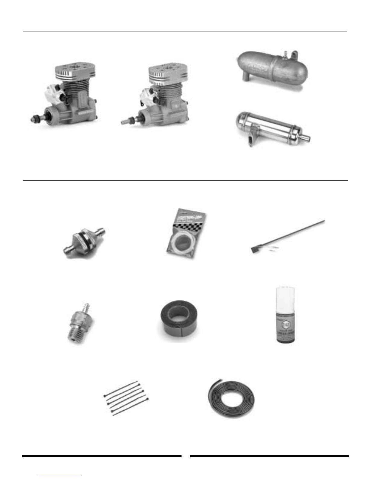
Items Required to Complete the JR Ergo . . . . . . . . . . . . . . . . . . . . . . . . . . .4–6
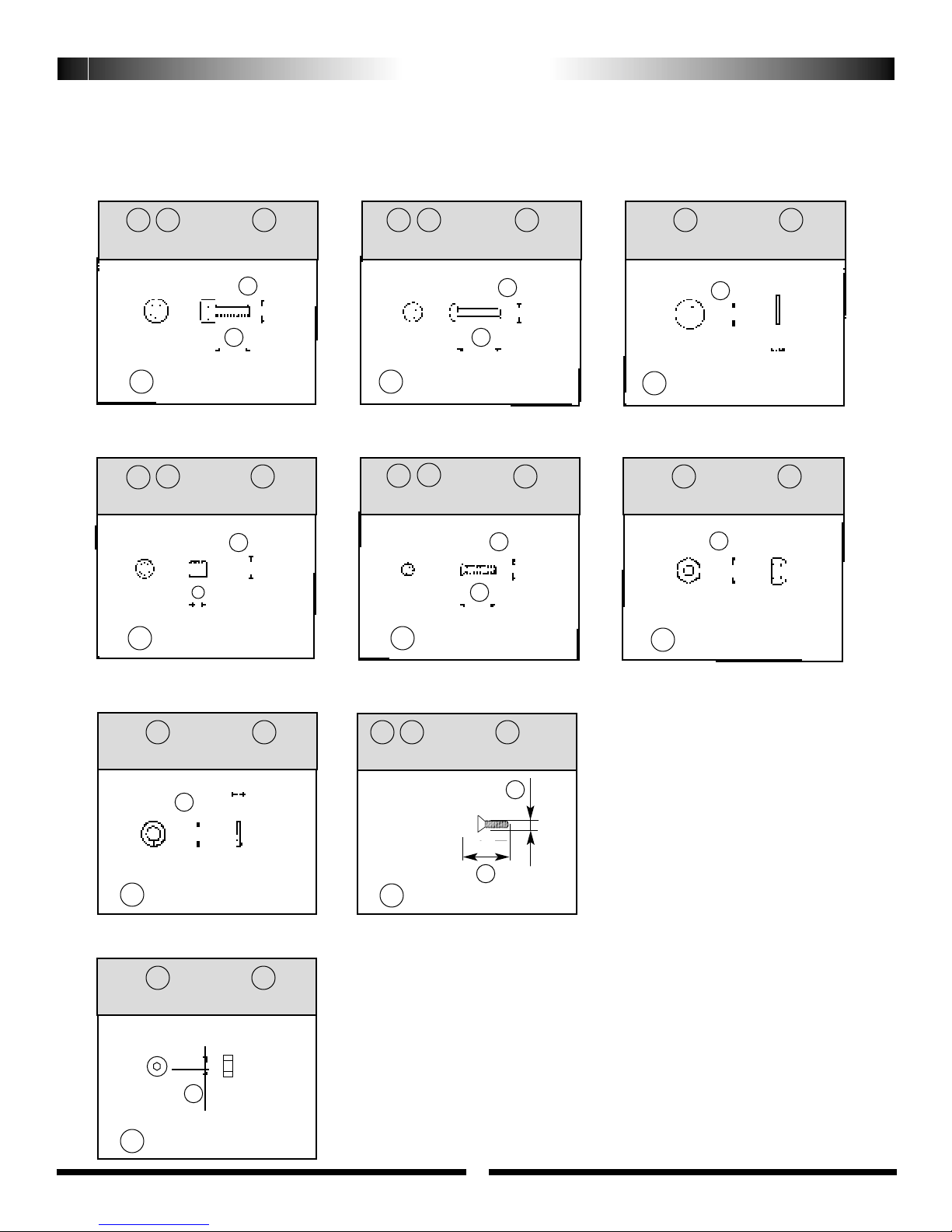
Hardware Identification . . . . . . . . . . . . . . . . . . . . . . . . . . . . . . . . . . . . . . . . . . .7
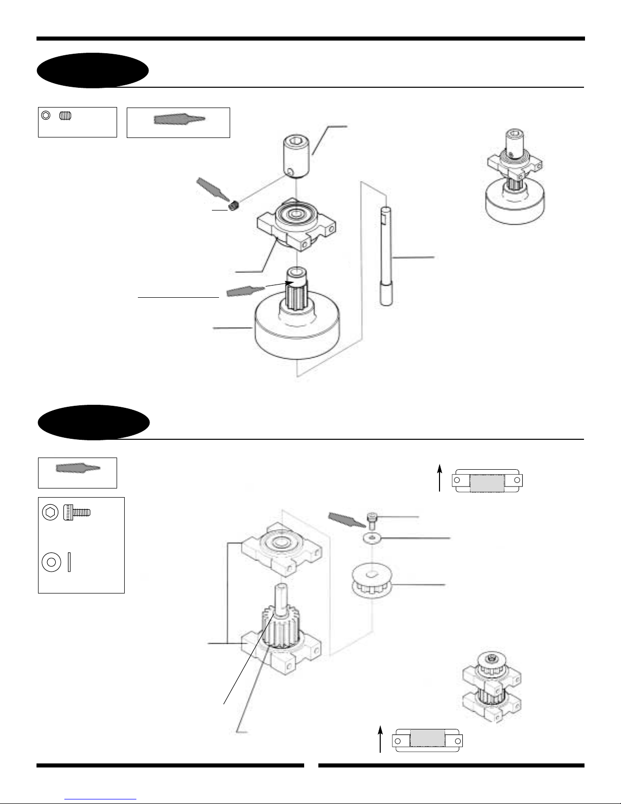
1-1 Clutch Bell/Start Shaft Assembly . . . . . . . . . . . . . . . . . . . . . . . . . .8
1-2 Tail Drive Pinion/Bearing Block Assembly . . . . . . . . . . . . . . . . . . .8
1-3 Elevator Arm Assembly . . . . . . . . . . . . . . . . . . . . . . . . . . . . . . . . .9
1-4 Fuel Tank Assembly . . . . . . . . . . . . . . . . . . . . . . . . . . . . . . . . . . .9
2-1 Upper Main Frame Section Assembly . . . . . . . . . . . . . . . . . . . . .10
2-2 Upper Main Frame Clutch/Tail Pinion Installation . . . . . . . . . . . .11
2-3 Lower Main Frame Assembly . . . . . . . . . . . . . . . . . . . . . . . . . . .12
2-4 Fuel Tank Installation . . . . . . . . . . . . . . . . . . . . . . . . . . . . . . . . . .12
2-5 Front Radio Bed/Gyro Mounting Plate Installation . . . . . . . . . . . .13
2-6 Cooling Fan Shroud Installation . . . . . . . . . . . . . . . . . . . . . . . . .13
2-7 Upper/Lower Main Frame Assembly Attachment . . . . . . . . . . . .14
3-1 Main Drive Gear/Autorotation Assembly . . . . . . . . . . . . . . . . . . .15
3-2 Main Drive Gear/Autorotation Assembly Installation . . . . . . . . . .15
3-3 Landing Gear Assembly Installation . . . . . . . . . . . . . . . . . . . . . .16
3-4 .32–.36 Cooling Fan/Hub Installation . . . . . . . . . . . . . . . . . . . . .16
3-4.1 .46 Cooling Fan Installation . . . . . . . . . . . . . . . . . . . . . . . . . . . . .17
3-5 .32–.36 Engine Mount Attachment . . . . . . . . . . . . . . . . . . . . . . .17
3-5.1 .46 Engine Mount Attachment . . . . . . . . . . . . . . . . . . . . . . . . . . .18
3-6 Clutch Assembly Attachment (All) . . . . . . . . . . . . . . . . . . . . . . . .18
3-7 Engine Installation (All) . . . . . . . . . . . . . . . . . . . . . . . . . . . . . . . .19
3-8 Installation of the Muffler . . . . . . . . . . . . . . . . . . . . . . . . . . . . . .19
4-1 Rotor Head Hub Assembly . . . . . . . . . . . . . . . . . . . . . . . . . . . . .20
4-2 Main Blade Holder Assembly . . . . . . . . . . . . . . . . . . . . . . . . . . . .20
4-3 Main Blade Holder/Seesaw Attachment . . . . . . . . . . . . . . . . . . . .21
4-4 Seesaw Mixing Arm Installation . . . . . . . . . . . . . . . . . . . . . . . . .21
4-5 Swashplate Adjustment . . . . . . . . . . . . . . . . . . . . . . . . . . . . . . . .22
4-6 Swashplate/Washout Assembly Installation . . . . . . . . . . . . . . . .22
4-7 Rotor Head Installation . . . . . . . . . . . . . . . . . . . . . . . . . . . . . . . .23
4-8 Flybar Installation . . . . . . . . . . . . . . . . . . . . . . . . . . . . . . . . . . . .24
4-9 Flybar Paddle Attachment . . . . . . . . . . . . . . . . . . . . . . . . . . . . . .24
4-10 Rotor Head/Swashplate Control Rod Installation . . . . . . . . . . . . .25
5-1 Tail Output Shaft/Pulley Assembly . . . . . . . . . . . . . . . . . . . . . . . .26
5-2 Tail Gear Case Assembly . . . . . . . . . . . . . . . . . . . . . . . . . . . . . . .26
5-3 Tail Center Hub Assembly . . . . . . . . . . . . . . . . . . . . . . . . . . . . . .27
5-4 Tail Blade Holder Assembly . . . . . . . . . . . . . . . . . . . . . . . . . . . . .27
5-5 Tail Pitch Control Lever Installation . . . . . . . . . . . . . . . . . . . . . . .28
5-6 Tail Fin Attachment . . . . . . . . . . . . . . . . . . . . . . . . . . . . . . . . . . .28
5-7 Tail Boom Carrier Installation . . . . . . . . . . . . . . . . . . . . . . . . . . .29
5-8 Tail Boom Assembly Installation . . . . . . . . . . . . . . . . . . . . . . . . .29
5-9 Tail Boom Brace Assembly . . . . . . . . . . . . . . . . . . . . . . . . . . . . .30
5-10 Tail Boom Brace Installation . . . . . . . . . . . . . . . . . . . . . . . . . . . .30
6-1 Servo Installation . . . . . . . . . . . . . . . . . . . . . . . . . . . . . . . . . . . .31
6-2 Tail Control Rod Assembly . . . . . . . . . . . . . . . . . . . . . . . . . . . . .32
6-3 Tail Control Rod Installation . . . . . . . . . . . . . . . . . . . . . . . . . . . .32
6-4 Gyro/Receiver/Switch Harness/Battery Installation . . . . . . . . . . .33
Understanding Swashplate Control Systems . . . . . . . . . . . . .34–35
How JR 120 CCPM Works . . . . . . . . . . . . . . . . . . . . . . . . . . . . . .36
Radio System Preparation . . . . . . . . . . . . . . . . . . . . . . . . . . .36–40
Radio System Requirements . . . . . . . . . . . . . . . . . . . . . . . . . . . .36
CCPM Software Activation and Initial Adjustment . . . . . . . . . . . .37
Important CCPM Programming Dos and Don’ts . . . . . . . . . . . . .40
7-1 Servo Arm Preparation & Installation . . . . . . . . . . . . . . . . . . . . .41
7-2 CCPM Servo Centering with the Sub-Trim Function . . . . . . . . . .42
7-3 CCPM Linkage Connections . . . . . . . . . . . . . . . . . . . . . . . . . . . .43
7-4 Checking the Swashplate for Level . . . . . . . . . . . . . . . . . . . . . . .44
7-5 Pitch-to-Aileron Mixing Adjustment w/Travel Adjust . . . . . . . . . .45
7-6 Pitch-to-Elevator Mixing Adjustment w/Travel Adjust . . . . . . . . .46
7-7 Tail Control Rod Servo Connection . . . . . . . . . . . . . . . . . . . . . . .47
8-1 Body Assembly/Canopy Attachment . . . . . . . . . . . . . . . . . . . . . .49
8-2 Body Attachment . . . . . . . . . . . . . . . . . . . . . . . . . . . . . . . . . . . . .49
8-3 Main Rotor Blade Balancing . . . . . . . . . . . . . . . . . . . . . . . . . . . .51
8-4 Main Rotor Blade Attachment . . . . . . . . . . . . . . . . . . . . . . . . . . .51
Final Servo Adjustment and Radio Set–Up . . . . . . . . . . . . . . . . . . . . . . . .52–54
Data Sheets . . . . . . . . . . . . . . . . . . . . . . . . . . . . . . . . . . . . . . . . . . . . . . .55–66
Final Pre-Flight Check . . . . . . . . . . . . . . . . . . . . . . . . . . . . . . . . . . . . . . . . . . .67
General Maintenance . . . . . . . . . . . . . . . . . . . . . . . . . . . . . . . . . . . . . . . . . . . .68
Rotor Head Assembly . . . . . . . . . . . . . . . . . . . . . . . . . . . . . . . . . . . . . . . . . . .69
rotor Head Assembly Parts List . . . . . . . . . . . . . . . . . . . . . . . . . . . . . . . . . . . .70
Start Shaft/Clutch/Engine Assembly . . . . . . . . . . . . . . . . . . . . . . . . . . . . . . . .71
Start Shaft/Clutch/Engine Assembly Parts List . . . . . . . . . . . . . . . . . . . . . . . .72
Washout Unit/CCPM Control System Parts . . . . . . . . . . . . . . . . . . . . . . . . . . .73
Cyclic Mixing Arms/Elevator/Aileron Control Arms Parts List . . . . . . . . . . . . .74
Upper Main Frame/Body Set/Main Gear Assembly . . . . . . . . . . . . . . . . . . . . .75
Upper Main Frame/Radio Tray/Body Set Parts List . . . . . . . . . . . . . . . . . . . . .76
Lower Main Frame/Landing Gear/Fuel Tank Assembly . . . . . . . . . . . . . . . . . .77
Lower Main Frame/Landing Gear/Fuel Tank Parts List . . . . . . . . . . . . . . . . . . .78
Tail Boom/Tail Blade/Tail Pitch Plate Assembly . . . . . . . . . . . . . . . . . . . . . . . .79
Tail Boom/Tail Blade/Tail Pitch Parts List . . . . . . . . . . . . . . . . . . . . . . . . . . . . .80
Tail Boom/Tail Brace/Tail Boom Carrier Assembly . . . . . . . . . . . . . . . . . . . . . .81
Tail Boom/Tail Brace/Tail Boom Carrier Parts List . . . . . . . . . . . . . . . . . . . . . .82
INDEX
Section Description Page Section Description Page

INTRODUCTION
Congratulations on your purchase of the JR Ergo helicopter kit.
This kit has been both engineered and manufactured by JR with help from some of
Japan’s top R/C helicopter engineers now employed by JR.
As you may well know, for years the name JR has been synonymous with state-of-
the-art, high quality radio control systems known the world over for their
exceptional reliability and engineering.
JR now brings this reputation and knowledge into the helicopter market with the
development of the Ergo and the organization of the JR heli division. Years in the
making, the Ergo’s superior quality and exceptional parts fit and finish create a new
standard of quality that was previously unavailable.
JR CCPM
To take the Ergo design to the next level, JR’s designers turned to CCPM
(Cyclic/Collective Pitch Mixing). CCPM is a unique control system that mounts
3 servos below the swashplate with short, straight linkages directly to the
swashplate at 120 degree intervals. With CCPM, complex collective and cyclic
mixing is accomplished electronically, rather than mechanically. As a result, many
parts are eliminated, along with excessive control system play, not to mention
quicker building and lower maintenance.
What’s more, you get more servo power from CCPM. That’s because instead of one
servo moving the collective, you now have three. Instead of one servo moving the
cyclic, you have two.
Before you begin the assembly of your Ergo CCPM, we suggest that you first
review the entire instruction manual to become familiar with the assembly
sequences and parts layout.
Warning
The radio controlled model helicopter contained in this kit is not a toy, but a
sophisticated piece of equipment. This product is not recommended for use by
children. Radio controlled models such as this are capable of causing both
property damage and/or bodily harm to both the operator/assembler and/or
spectator if not properly assembled and operated. Horizon Hobby Distributors
assumes no liability for damage that could occur from the assembly and/or
use/misuse of this product.
AMA Information
We strongly encourage all prospective and current R/C aircraft pilots to join the
Academy of Model Aeronautics. The AMA is a non-profit organization that provides
services to model aircraft pilots. As an AMA member you will receive a monthly
magazine entitled Model Aviation, as well as a liability insurance plan to cover
against possible accident or injury. All AMA charter aircraft clubs require
individuals to hold a current AMA sporting license prior to operation of their
models. For further information, you can contact the AMA at:
Academy of Model Aeronautics
5151 East Memorial Drive
Muncie, IN 47302
(317) 287-1256
Pre-Assembly Information
When first opening your Ergo kit, you will notice that all of the parts are packaged
and numbered to coordinate with the assembly step numbers of this instruction
manual.
All small hardware (nuts, bolts, washers, etc.) for each step are separated and
packaged separately within the main parts bags. When beginning a section, you will
need to open only the bag with the corresponding number to the section you are
about to start. It is suggested that you place all of the hardware in an open
container (e.g., coffee can) during assembly so as not to lose any of the small
parts. It may also be helpful to familiarize yourself with the various sizes of screws,
bolts, nuts, etc., as illustrated in the appropriate assembly section before you begin
assembly. In most cases, at the end of each assembly section there should be no
parts remaining.
Great care has been taken in filling the bags with the correct quantity of parts and
hardware for each section. However, occasionally mistakes do happen. In the event
that you find a parts shortage or are in need of technical assistance, please contact
your local JR heli division parts dealer, or contact the Horizon Service Center
directly.
Horizon Service Center
4105 Fieldstone Road
Champaign, IL 61822
(217) 355-9511 (9am to 5pm CST)
3

ADDITIONAL ITEMS REQUIRED TO COMPLETE THE JR ERGO
1. RADIO SYSTEM REQUIREMENTS (NOT INCLUDED):
6-channel or greater R/C helicopter system with 120°CCPM function (see list below), 5 servos, 1000 mAh receiver battery and gyro.
ERGO .32–.36 AND ERGO .46 3D FEATURES
CCPM (Cyclic/Collective Pitch Mixing):
More Accurate: Control system play is totaly eliminated.
Simpler: Fewer links to set-up and maintain.
More Powerful: Collective has three times the servo power, cyclic has double.
Heavy-Duty Aluminum Quad Frame System
Provides excellent rigidity and vibration absorption.
One-Way Hex Start Shaft System
Provides positive starting. Starter shaft utilizes a one-way bearing
that allows the shaft to stop after the engine is started.
Wide Spread Tail Output Shaft Bearings
Reduces vibration and improves control response.
Belt-Driven Tail Rotor Design
Provides easy adjustment and low maintenance. Also eliminates
the need for optional/expensive tube drive shafts.
Precision Ball Bearings at All Critical Locations
Provide low wear, high precision and reduced maintenance.
Self-Aligning One-Piece Steel Clutch System
Offers easy installation and adjustment with exceptional reliability.
Straight Blade Axle Rotor Head Design
Provides high responsiveness and solid blade tracking.
Low Drag Flybar Paddles
Provide quick yet smooth cyclic response at all flight speeds.
Heavy-Duty Main Blade Grips with 4mm Blade Bolts
Provide a solid and secure mounting surface to easily handle
the stresses of radical 3D flight.
Rearward-Facing Engine Design
Provides easy access to the glow plug for starting. Engine slips
easily through the main frame for trouble-free engine maintenance.
Heavy-Duty Tail Boom Carrier
Provides increased structural rigidity and improved tail rotor precision.
Pre-Finished Main Rotor Blades
Provide easy assembly with excellent flight characteristics.
Superior Parts Fit and Finish
Make assembly trouble free and enjoyable.
4
CCPM-Ready JR Radio Systems
Most current JR Heli radio systems (XP652,
XP8103 w/digital trims, 10X, as well as older
10 series systems) are equipped with 120°
CCPM electronics for use with the Ergo
CCPM machines. Radios you may be flying
now, like the X347, X388S, XP783, and
XP8103* have CCPM capability built in, but
require activation by the
Horizon Service Department.
Please call (217) 355-9511 for details.
*Please note that many XP8103 systems have the CCPM
function already activated. Please check with the Horizon
Service Center for details.
CURRENT RADIO SYSTEMS
JRP1656** PCM 10X, 5-8231 Servos (50/53/72 MHz)
JRP165TX PCM 10X, Transmitter Only (50/53/72 MHz)
JRP8622** XP8103FM, 5-517 Servos (50/53/72 MHz)
JRP8653** XP8103PCM, 5-531 Servos (50/53/72 MHz)
JRP6622** XP652 FM, 5-517 Servos (50/53/72 MHz)
12'' Aileron Extensions (2)450 Piezo GyroJR AirPac
JR XP652 JR 10X JR XP8103 DT

5
Double Sided Servo
Mounting Tape
Threadlock
(Blue and Red Required)
Nylon Wire Ties To
Secure Radio Wires
Heavy-Duty Servo
Arms (3)
Silicone Fuel Tubing Whip Antenna
Fuel Filter
Glow Plugs
2. ENGINE REQUIREMENTS (NOT INCLUDED):
3. BUILDING SUPPLIES (NOT INCLUDED):
The following items are needed to complete the assembly of the JR Ergo:
A .32–.38 R/C helicopter engine (Ergo .30) or .46–.48 R/C helicopter engine (Ergo .46) A special helicopter type muffler is also required
(MDS .38 Heli Engine Shown) (MDS .48 Heli Engine Shown)
(JRP960078 Ergo .32–.36 Muffler Shown)
(JRP960079 Ergo .46 Muffler Shown)

6
Needle Nose Pliers
Drill and Drill Bits
Allen Wrenches: 1.5, 2.0, 2.5,
3.0mm
Ball Link Pliers Ball Link Sizing ToolBlade Balancer
Small Hammer X-Acto Knife Metric Ruler
Scissors
12 Volt Electric Starter 12 Volt Starting Battery 1.5 Volt Glow Plug Battery Remote Glow Plug Adaptor
Helicopter Fuel, 15% –30%
Pitch Gauge
Fuel Pump
Training Gear (Beginners Only)
Hex Starting Shaft
Phillips Screwdriver Nut Drivers: 5mm, 7mm
4. TOOLS NEEDED TO ASSEMBLE THE JR ERGO (NOT INCLUDED):
5. FIELD EQUIPMENT REQUIRED (NOT INCLUDED):
or

7
Socket Head Bolt Tapping Screw Flat Washer
.05mm
.05mm
Flat Head Screw Lock Nut
There are many various sizes and shapes of hardware included in this kit.
Prior to assembly, please be careful to identify each screw by matching it to the full
size screw outlines included in each step.
All of the hardware, screws, nuts, etc., contained in the Ergo kit are described in the
following A, B, C manner:
CC
C
A
B
A
A
B
B
C
3x8mm Socket Head Bolt
Set Screw
C
A
B
C
C
A
A
A
2x8mm Flat Head Screw
2.6x10mm Self Tapping Screw
AB
B
3mm Flat Washer
AB
B
3mm Lock Nut
Spring Washer
AB
B
3mm Spring Washer
A
Hex Nut
AB
B
2mm Hex Nut
C
4x4mm Set Screw
HARDWARE IDENTIFICATION
A
B
Flat Head Cap Screw
AC
B
C
3x8mm Flat Head Cap Screw
ABAB
ABAB

8
1-1
3x4mm Set Screw
3x4mm Set Screw
* When installing the Start Shaft
Bearing Block Assembly, be sure
the Bearing Block is positioned so
the small inside diameter bearing
faces upward toward the starter
hex adaptor, with the large inside
diameter bearing toward the
Clutchbell Assembly.
Starter Hex Adaptor
*Start Shaft Bearing Block
with ball bearing
Apply a very light coat of Red
Threadlock before inserting
pinion gear into the start
shaft bearing block
Start Shaft
Complete Assembly
Clutch Bell Assembly
..........1 pc
3x6mm Socket Head Bolt
...1 pc
3mm Flat Washer
.........1 pc
CLUTCH BELL/START SHAFT ASSEMBLY
1-2 TAIL DRIVE PINION/BEARING BLOCK ASSEMBLY
Install the Lower Bearing Block so the
bearing face is toward the top:
Install the Upper Bearing Block so that
the bearing is toward the bottom:
Note: Be sure to allow a slight amount of
clearance between the Start Hex
Adaptor and the Bearing Block to
prevent binding.
Tail Drive Pinion
Bearing Blocks
Tail Drive Pinion
with Shaft
Front Tail Belt Pulley
(Install Flat Side Up)
3mm Flat Washer
3x6mm Socket Head Bolt
Complete Assembly
UP
UP
Bearing
Bearing
Use Red Threadlock
Use Red
Threadlock
Use Blue & Red Threadlock

1-3 ELEVATOR ARM ASSEMBLY
9
Swashplate A Arm
JR Logo Direction
Elevator Arm
11mm Long Ball Arm
3mm Flat Washer
Swashplate A Arm
Edge of Work Bench
Elevator Arm
Tap-in gently with
a small hammer.
Elevator Arm Pin
3mm Lock Nut
Caution: Be sure to note the correct Swashplate A
Arm installation direction.
Elevator Arm
Marked Side Out
Swashplate A
Arm
After assembly, check to be sure the
Fuel Tank Clunk can move from the
bottom to the top of the tank without
touching the back wall of the Fuel Tank.
Fuel Tank
Silicone Fuel Tubing
(not incuded)
Connects to Engine Carburetor
* Trim before installation to a length of 58mm
Nipple
Tank Grommet
* Silicone Tube (Small)
Fuel Tank Clunk
Silicone Fuel Tubing
(not included)
Connects to Muffler Pressure Tap
1-4 FUEL TANK ASSEMBLY
3mm Lock Nut
11mm Long Ball Arm
Elevator Arm Pin
3mm Flat Washer
................1 pc
....1 pc
...1 pc
....................1 pc

10
2-1 UPPER MAIN FRAME SECTION ASSEMBLY
5mm Nylon Washer Main Frame Standoff, 32mm
Body Mounting Standoff, 37mm
3x8mm Socket Head Bolt
Slot denotes left frame side
3x8mm Socket Head Bolt
Bearing side must face
downward
3X8mm Socket Head Bolt
Use Threadlock
Use Threadlock
Use Threadlock
Use Threadlock
Upper Main Frame, Left
Upper Main Frame, Right
Main Frame Standoff,
32mm (3)
*Elevator Arm from Step 1-3
Elevator Arm Bushing, 32mm
5mm Nylon Washer
Body Mounting Standoff, 37mm
Use Blue Threadlock On All Screws
Upper Main Shaft Bearing Block
Position so the side
of the bearing block
that has the bearing
flush with the flange
is upward.
UP
Lower Main Shaft Bearing Block
UP
Bearing Flush
with Flange
Bearing
Bearing
Position so side of
the bearing block
that has the bearing
flush with the flange
is downward.
Bearing side must
face upward
*Note: Install elevator arm
assembly first!
Note: Be sure to note left & right
upper main frame positions
. . . . . . . 18 pcs
. . . . . . . . . . . . 2 pcs . . . . . 2 pcs
. . . . . 1 pc
2 pcs
3x8mm Socket Head Bolt
Elevator Arm Bushing, 32mm
Bearing Flush
with Flange

2-2 UPPER MAIN FRAME CLUTCH/TAIL PINION INSTALLATION
11
3x8mm Socket Head Bolt
Clutch Bell/Start Shaft Assembly Tail Drive Pinion/Bearing
Block Assembly
3x8mm Flat Washer
Tail Control
Rod Guide
Note: Both the Clutch Bell/Start Shaft Assembly
(Step 1-1) and the Tail Drive Pinion/
Bearing Block Assembly (Step 1-2) are
temporarily installed at this time. These
assemblies will be adjusted and secured
in Step 3-2.
3x10mm Socket Head Bolt
3x8mm Socket Head Bolt
3x10mm Socket Head Bolt
3mm Flat Washer
. . . . . . . . . . . . . . . . 11 pcs
. . . . . . . . . . . . . . . . . 1 pc
. . . . . . . . . . . . . . . . . . . . . . 11 pcs

2-3 LOWER MAIN FRAME ASSEMBLY
3x8mm Socket Head Bolt
.... 4 pcs
3mm Lock Nut
........4 pcs
2.6x8mm Self Tapping Screw
........4 pcs
2-4 FUEL TANK INSTALLATION
Note: Install the Fuel Tank and Tank Mounting Rubber into the lower frame halves
before attaching the Main Frame Standoffs.
When securing the Standoffs to the frame, position the bottoms of the level
surface to prevent twisting during tightening.
12
2.6x8mm Self Tapping Screw (4 pcs)
3x8mm Socket
Head Bolt
2.6x8mm Self Tapping Screw
Servo Mounting Plate
3x8mm Socket Head Bolt (4 pcs)
Lower Main Frame
3mm Lock Nut
(4 pcs) Lower Frame Angle (2 pcs)
Main Frame Standoff, 60mm
Main Frame
Standoff, 60mm
Main Frame Standoff,
60mm
3x10mm Socket
Head Bolt (4 pc)
Tank Mounting
3x8mm Socket Head Bolt
Fuel Tank
3x8mm Socket
Head Bolt
Tank Mounting
Lower Main Frame
3x8mm Socket Head Bolt
........2 pcs
3x10mm Socket Head Bolt
........4 pcs
Main Frame Standoff, 60mm ........ 3 pcs
Use Threadlock
Use Blue Threadlock

2-5 FRONT RADIO BED/GYRO MOUNTING PLATE INSTALLATION
2-6 COOLING FAN SHROUD INSTALLATION
13
3x18mm Set Screw
Body Mounting Standoff, Long........2 pcs
3x10mm Socket Head Bolt
........6 pcs
........2 pcs
2.6x8mm Self Tapping Screw
........4 pcs
When installing a .46–.48 size engine,
it’s necessary to trim the bottom
portion of the Fan Shroud as shown:
Front Radio Bed
Body Mounting
Standoff, Long
3x10mm Socket
Head Bolt
2.6x8mm Self
Tapping Screw
Cooling Fan Shroud
2.6x8mm Self Tapping Screw
3x18mm Set Screw (2 pcs)
Body Mount Standoff, Long
Use Threadlock
3x10mm Socket
Head Bolt (6 pcs)
Gyro Mounting Plate
Ergo .46 Fan Shroud Adjustment
3/4"1 7/8"
Remove
Use Blue Threadlock

2-7 UPPER/LOWER MAIN FRAME ASSEMBLY ATTACHMENT
14
32mm Main Frame Standoff (6 pcs)
Use Threadlock
32mm Main Frame Standoff
12.5mm Main Frame Spacer
3x22mm Socket Head Bolt
3x22mm Socket Head Bolt (12 pcs)
12.5mm Main Frame Spacer (12 pcs)
Use Blue Threadlock
on all screws
........12 pcs
........12 pcs
........6 pcs

15
3-1 MAIN DRIVE GEAR/AUTOROTATION ASSEMBLY
3-2 MAIN DRIVE GEAR/AUTOROTATION ASSEMBLY INSTALLATION
3x6mm Socket Head Bolt
2. Secure the Autorotation Hub to the Main Rotor
Shaft using the 3x22mm Socket Head Bolt. Next,
slide the Main Shaft Collar onto the Main Rotor
Shaft. While pulling upward on the Main Rotor
Shaft, secure the Main Shaft Collar to the Main
Rotor Shaft using the four 4x4mm Set Screws.
1. Once the Main Shaft Assembly is in place,
adjust the gear mesh of the Clutch Bell
and Tail Belt Pinion Gears and secure the bolts
left loose from Step 2-1.
3x6mm Socket Head Bolt (4 pcs)
[Tighten equally to prevent
warping of Main Drive Gear]
Main Drive Gear
Use Threadlock
Autorotation Assembly
Main Shaft Collar
4x4mm Set Screw
3x22mm Socket Head Bolt
3mm Lock Nut
8mm
3mm
Main Rotor
Shaft
Use Threadlock
3mm Lock Nut
Autorotation
Assembly from
Step 3-1 3x22mm Socket
Head Bolt
Use Blue Threadlock
. . . . . . . . . . . . . 4 pcs
. . 1 pc
. . . . . . . . . . . . . . 1 pc
......4 pcs
Use Blue Threadlock
4x4mm Set Screws (4)

3-3 LANDING GEAR ASSEMBLY INSTALLATION
16
3mm Lock Nut
........4 pcs
3x12mm Socket Head Bolt
........4 pcs
3mm Flat Washer
........4 pcs
4x4mm Set Screw
........4 pcs
Note: If you are building the Ergo .46 3D Version,
proceed to Step 3-4.1
O.S. .32SX-H Installation
For proper installation of this engine, it will be
necessary to purchase the O.S. Prop Drive
Washer for this engine (Part #23408000).
*It is recommended that a Piston Locking Tool
be used to properly secure the Fan Assembly to
the engine.
3x5mm Socket Head Bolt
........4 pcs
3x12mm Socket Head Bolt (4 pcs)
3mm Flat Washer (4 pcs)
Landing Strut
Landing Gear Dampers (4 pcs)
Landing Skid Cap
Landing Skid
20mm
Antenna Tube
4x4mm Set Screw (4 pcs)
3mm Lock
Nut (4 pcs)
Cooling Fan Hub .32-.36
Cooling Fan .32-.36
Nut Supplied with Engine
Use Threadlock
3x5mm Socket
Head Bolt (4 pcs)
Use Blue Threadlock
For proper installation of the fan assembly, it’s neccessary
for the engine to have the prop drive washer installed.
MDS .38 Heli engine shown *Revolution 1003 Piston Locking Tool
(Purchased Separately)
Use Threadlock
3-4 .32–.38 CO0LING FAN/HUB INSTALLATION

3-4.1 .46 COOLING FAN INSTALLATION
3-5 .32–.36 ENGINE MOUNT ATTACHMENT
Note: If you are building the Ergo .46 3D Version proceed to Step 3-5.1.
Longer Distance
Shorter Distance
Note: If you’re building the Ergo .32–.36 Version, proceed to Step 3-5.
Note: It will not be necessary to use the four 3x5mm
Socket Head Bolts included in this screw bag.
Note: It will be necessary to shorten the Crankshaft of
the engine to allow clearance. Test fit the Fan
Assembly to determine the correct amount of the
crankshaft to be removed. On the Thunder Tiger
Pro .46 and MDS .48 Heli Engine, it will be
necessary to remove 1/2" from the tip of the
Crankshaft.
*It is recommended that a Piston Locking Tool be used to
properly secure the Cooling Fan Assembly to the engine.
17
3x15mm Socket Head Bolt
3mm Flat Washer
........4 pcs
3mm Serrated Washer
........4 pcs
Motor Mount Direction
Engine Mount .32–.36
3mm Serrated
Washer (4 pcs)
3x15mm Socket
Head Bolt
Use Threadlock
Use Threadlock
3mm Flat
Washer (4 pcs)
Nut Supplied with Engine
It is important to note the proper direction for the motor mount
installation for achieving the correct alignment of the engine.
Aluminum Cooling Fan
(Ergo .46)
......4 pcs
* Revolution 1003 Piston Locking Tool
(Purchased Separately)
MDS .48 Heli engine
Use Threadlock
Use Blue Threadlock
Use Blue Threadlock
Top
Bottom

3-5.1 .46 ENGINE MOUNT ATTACHMENT
3-6 CLUTCH ASSEMBLY ATTACHMENT (ALL)
18
It is important to note the proper direction that the Motor Mount
is installed to achieve the correct alignment of the engine.
*Note: When installing an O.S. brand engine, it may be
neccessary to add additional washers under the bolt
heads to allow proper clearance to the engine mounting
bolts.
3mm Flat Washer
........4 pcs
3x15mm Socket Head Bolt
........4 pcs
3mm Serrated Washer
........4 pcs
2x8mm Flat Head Screw
........1 pc
3mm Flat Washer
........2 pcs
Steel Joint Ball
........1 pc
3x5mm Socket Head Bolt
........2 pcs
2mm Hex Nut
........1 pc
.46 Engine Mount
.46 Fan Assembly
3mm Serrated
Washer (4 pcs)
3x15mm Socket
Head Bolts (4 pcs)
Use Threadlock
Shorter Distance
Longer Distance
*See Note
Longer Distance
3mm Flat
Washer (4 pcs)
2mm Hex Nut
Clutch Assembly
3mm Flat Washer
(2 pcs)
3x5mm Socket Head Bolt
(2 pcs)
2x8mm Flat
Head Screw
Steel Joint Ball
*See Note
Top
Bottom Bottom
Motor Mount Direction:
Thunder Tiger
Motor Mount Direction:
O.S./MDS
Thunder Tiger
Pro .46
Top
O.S..46FS
R-H
Shorter Distance
Use Threadlock
Use Threadlock
Use Blue Threadlock
Use Blue Threadlock

3-7 ENGINE INSTALLATION (ALL)
3-8 INSTALLATION OF THE MUFFLER
19
Pressure Tap
........1 pc
3x30mm Socket Head Bolt .......2 pcs
Adjust the height and position of the Engine
as shown so the bottom of the Clutch
Assembly is flush with the bottom of the
Clutch Bell. Also check to insure that the
Engine and Clutch Bell are parallel.
*It is highly recommended that you insert
the Muffler Bolts into the Engine Case prior
to installing the engine in the frame.
3mm Flat Washer
........4 pcs
3mm Flat Washer (4 pcs)
3x8mm Socket Head Bolt
Pressure Fuel Line Attachment
JR .32–.36 Muffler Shown
(Purchased Separately,
JRP960078)
Pressure Tap
Correct Incorrect
See note in step 3-5.1
Note: The installation shown is for a .32–.36 size engine with a JR muffler (JRP960078). Installation of
other .32–.36/.46 engine muffler combinations may vary. Please refer to your engine/muffler
instructions for proper installation.
Use Blue Threadlock
on all screws
Use Threadlock
.......4 pcs
3x8mm Socket Head Bolt
Use Threadlock
Use Blue Threadlock

20
4-1 ROTOR HEAD HUB ASSEMBLY
4-2 MAIN BLADE HOLDER ASSEMBLY
3x6mm Socket Head Bolt
........1 pc
3x8mm Socket Head Bolt
......2 pcs
2x10mm Flat Head Screw
........1 pc
Steel Joint Ball
........1 pc
3x6mm Self Tapping Screw
........4 pcs
Main Blade Holder Bearing
........2 pcs
Outer Main Blade Bearing Spacer
........1 pc
Inner Main Blade Bearing Spacer
........1 pc
3x6mm Socket Head Bolt
Use Threadlock
Use Threadlock
Head Button
3x8mm Socket Head Bolt
(2 pcs)
Two Sets Required
Main Blade Holder Bearing
Main Blade Holder
Main Blade Holder Bearing
Steel Joint Ball
2x10mm Flat Head Screw
Outer Main Blade Bearing Spacer
Inner Main Blade Bearing Spacer
3x6mm Self Tapping Screw
Use Blue Threadlock
Main Rotor Hub
Note: If you’re building the Ergo 46 3D CCPM
version, please refer to the separate assembly
instructions contained in the high cyclic
center hub assembly included with this kit.
Table of contents
Other JR Toy manuals
Popular Toy manuals by other brands

Radica Games
Radica Games 20Q instruction manual

Fisher-Price
Fisher-Price Surprise Sounds Fun Park LittlePeople B6313 manual

SG Models
SG Models Master P-47D Thunderbolt Assembly manual

Viessmann
Viessmann Vollmer 43537 Mounting instruction

Mattel
Mattel Hot Wheels MONSTER JAM OFF-ROAD MAXIMUM DESTRUCTION... instructions

Lionel
Lionel Greendale owner's manual

Playskool
Playskool Magic Screen Learning Pal 03488 instruction manual

Lionel
Lionel Lirr Passenger owner's manual

Traxxas
Traxxas 38104-1 operating instructions

Eduard
Eduard Super Mystere B.2 quick start guide

Maya Group
Maya Group Orbeez Crush CRUSHKINS SAFARI Instruction guide

LEXIBOOK
LEXIBOOK DANCE MAT PARTY instruction manual