JR Vibe 90SG User manual

ASSEMBLY INSTRUCTIONS
Vibe 90SG Specications
Overall Length..............................53.5 in (1359mm)
Height..............................................17.25 in (438mm)
Main Rotor Diameter .................... 63 in (1600mm)
Tail Rotor Diameter.....................11.34 in (288mm)
Gear Ratio ..........................................................8:1:4.65
Weight (no fuel)....10.25–10.75 lb (4.65–4.88 kg)
Control System..............................120 or 140 CCPM

2
INTRODUCTION ....................................................................................................................................................................... 4
KEY FEATURES.......................................................................................................................................................................... 4
PRE-ASSEMBLY WARNING ................................................................................................................................................... 5
RECOMMENDED RADIO SYSTEM ...................................................................................................................................... 5
ITEMS REQUIRED TO COMPLETE ASSEMBLY................................................................................................................. 6
1-1 CLUTCH BELL/START SHAFT ASSEMBLY......................................................................................................... 7
1-2 BEVEL GEAR ASSEMBLY........................................................................................................................................ 7
1-3 TAIL DRIVE TRANSMISSION ASSEMBLY.......................................................................................................... 8
1-4 T-ARM LEVER ASSEMBLY..................................................................................................................................... 8
1-5 ELEVATOR A-ARM ASSEMBLY............................................................................................................................ 9
1-6 DOUBLE MAIN DRIVE GEAR ASSEMBLY.......................................................................................................... 9
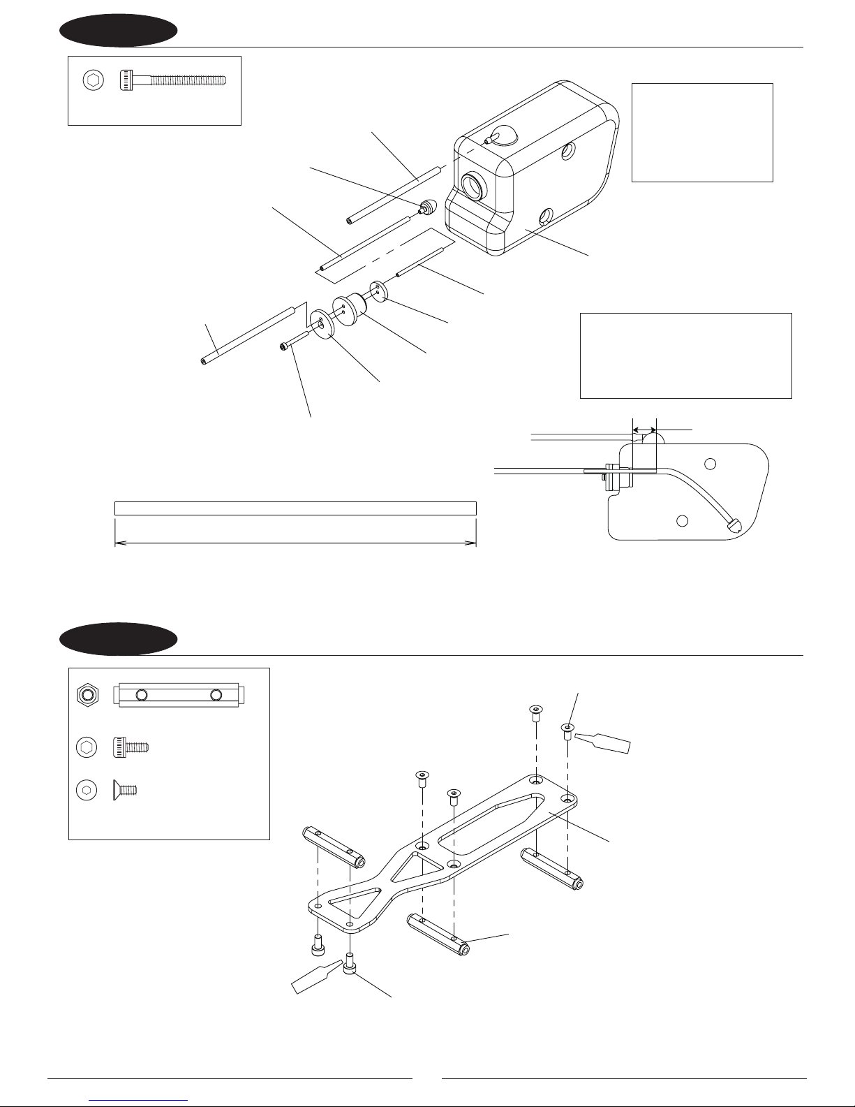
1-7 FUEL TANK ASSEMBLY........................................................................................................................................10
1-8 FRAME SUPPORT ASSEMBLY ............................................................................................................................10
1-9 FRONT TRAY ASSEMBLY..................................................................................................................................... 11
2-1 MAIN FRAME ASSEMBLY 1 ................................................................................................................................ 12
2-2 MAIN FRAME ASSEMBLY 2 ................................................................................................................................13
2-3 MAIN FRAME ASSEMBLY 3 ................................................................................................................................14
2-4 CLUTCH BELL INSTALLATION .......................................................................................................................... 15
2-5 TAIL PINION UNIT INSTALLATION .................................................................................................................. 16
2-6 CCPM LEVERS INSTALLATION .........................................................................................................................17
2-7 FRONT BED INSTALLATION ..............................................................................................................................18
2-8 GYRO TRAY/BRACKET ATTACHMENT ........................................................................................................... 19
2-9 TANK FRAME ASSEMBLY ................................................................................................................................... 20
2-10 FUEL TANK INSTALLATION ............................................................................................................................... 21
2-11 LANDING STRUTS ADAPTER INSTALLATION ...............................................................................................22
2-12 LANDING GEAR INSTALLATION ......................................................................................................................23
3-1 MAIN SHAFT/MAIN DRIVE GEAR INSTALLATION ......................................................................................24
3-2 COOLING FAN/CLUTCH INSTALLATION ....................................................................................................... 25
3-3 ENGINE INSTALLATION ......................................................................................................................................26
3-4 COOLING FAN SHROUD INSTALLATION ...................................................................................................... 27
3-5 INSTALLATION OF THE MUFFLER/FUEL LINE CONNECTIONS .............................................................. 28
4-1 SWASHPLATE/WASHOUT INSTALLATION ................................................................................................... 29
4-2 MIXING ARM INSTALLATION ............................................................................................................................ 30
4-3 ROTOR HEAD ASSEMBLY ...................................................................................................................................31
4-4 SEESAW SHAFT INSTALLATION .......................................................................................................................32
4-5 ROTOR HEAD INSTALLATION ........................................................................................................................... 33
4-6 CONTROL ROD INSTALLATION ....................................................................................................................... 34
TABLE OF CONTENTS
2

3
5-1 TAIL DRIVE SHAFT ASSEMBLY...........................................................................................................................35
5-2 TAIL BOOM INSTALLATION...............................................................................................................................35
5-3 TAIL GEAR CASE INSTALLATION 1...................................................................................................................36
5-4 TAIL GEAR CASE INSTALLATION 2..................................................................................................................37
5-5 TAIL PITCH CONTROL LEVER INSTALLATION..............................................................................................38
5-6 TAIL CENTER HUB ASSEMBLY............................................................................................................................39
5-7 TAIL BLADE HOLDER ASSEMBLY...................................................................................................................... 40
5-8 TAIL BOOM BRACE ASSEMBLY..........................................................................................................................41
5-9 TAIL BOOM BRACE INSTALLATION.................................................................................................................41
5-10 TAIL BELL CRANK INSTALLATION....................................................................................................................42
5-11 TAIL CONTROL ROD ATTACHMENT................................................................................................................43
RADIO SYSTEM PREPARATION........................................................................................................................................44
UNDERSTANDING THE CCPM CONTROL SYSTEMS........................................................................................... 45–46
IMPORTANT CCPM PROGRAMMING DO’S AND DON’TS........................................................................................47
CCPM SOFTWARE INITIAL ADJUSTMENTS...................................................................................................................48
JR 12X: PROGRAMMING ............................................................................................................................................. 49–52
JR X9303 2.4 AND XP9303: PROGRAMMING ..................................................................................................... 53–56
JR 7202 AND SPEKTRUM DX7se AND DX7: PROGRAMMING ........................................................................ 57–60
6-1 SERVO INSTALLATION 1.....................................................................................................................................61
6-2 SERVO INSTALLATION 2.....................................................................................................................................62
6-3 SERVO HORN INSTALLATION ........................................................................................................................... 63
6-4 CCPM CONTROL ROD ATTACHMENT............................................................................................................ 64
6-5 CHECKING THE SWASHPLATE FOR LEVEL .................................................................................................. 65
6-6 TAIL CONTROL LINKAGE ATTACHMENT ...................................................................................................... 66
6-7 THROTTLE LINKAGE ATTACHMENT ............................................................................................................... 67
6-8 GYRO/RECEIVER/BATTERY INSTALLATION.................................................................................................. 68
GENERAL RADIO SETUP INFORMATION................................................................................................................ 69–70
FINAL SERVO ADJUSTMENT AND RADIO SETUP........................................................................................................ 71
PITCH RANGE AND CURVE SETTINGS.............................................................................................................................. 72
7-1 BODY/MAIN ROTOR BLADE ATTACHMENT ................................................................................................ 73
FINAL PREFLIGHT CHECK................................................................................................................................................... 74
BLADE TRACKING ADJUSTMENT..................................................................................................................................... 74
BLADE TRACKING IDENTIFICATION................................................................................................................................75
GENERAL MAINTENANCE...................................................................................................................................................76
REPLACEMENT PARTS LISTING ............................................................................................................................... 78–101
WARRANTY INFORMATION ...................................................................................................................................102–104
3

4
Designed by world-class heli pilot Scott Gray, the latest addition to the Vibe family of helicopters oers the ultimate
in aggressive ight performance and is designed to withstand the stresses of the most extreme aerobatic and 3D
maneuvers, even those that have yet to be imagined. Features like the oversized tail and main shafts, the oversized
Sprag autorotation clutch and 10mm spindle shaft that can handle the most aggressive maneuvers, a robust split
gear constant-driven tail rotor and a lightweight, rigid structural design make the Vibe 90™ SG an unbeatable
choice for heli pilots who want to push 3D performance beyond the edge. If you’ve been waiting for a helicopter
design that has unlimited ight performance with the reliability and the durability to handle the most demanding
aerobatics…your wait is over. Once you take the controls of the Vibe 90 SG, you’ll know your wait was worth it.
• Fullytunablehi-cyclicheadforextremecyclicresponse
• 120/140CCPMsystem
• Driventailwithbearingsupportedaluminumshaft
• Acceptsthemostpopularhelicopterengines
• RobustSpragautorotationclutch
• Push-pullcycliclinkages
• Higheciencytwo-piecefanshroud
• StandardFlybarcage
• Easilyremoved,vibration-isolatedtank
• Dualradial,singlethrusttailbladegrips
• DualyokeT/Ractuator
• Includeshigh-qualityFRPberglassprepaintedcanopy
• All-newrotorheadsystemwithultra-rigiddampening
• Highlycongurablerotorheadsettings
• I-beamhighrigidityframeassembly
• OversizedMainandTailDrivetransmissions
• Self-aligning,easy-to-maintainenginemountsystem
INTRODUCTION
KEY FEATURES

5
When rst opening your helicopter, you will notice that all of the parts are packaged and numbered to coordinate
withtheassemblystepnumbersofthisinstructionmanual.Allsmallhardware(nuts,bolts,washers,etc.)foreach
step is separated and packaged separately within the main parts bags. When beginning a section, you will need to
open only the bag with the corresponding number to the section you are going to start. It is suggested that you
place all of the hardware in an open container (e.g., coee can) during assembly so as not to lose any of the small
parts. It may also be helpful to familiarize yourself with the various sizes of screws, bolts, nuts, etc., as illustrated
intheappropriateassemblysectionbeforeyoubeginassembly.Attheendofeachassembly,inmostcases,there
should be no parts remaining.
NOTE: Your kit also includes JR® red and green threadlock. Unlike conventional U.S.-made threadlock,
JR red is the U.S. equivalent of blue. JR green is the equivalent of U.S. red.
Greatcarehasbeentakeninllingthebagswiththecorrectquantityofpartsandhardwareforeachsection.
However, occasionally mistakes do happen. In the event that you nd a parts shortage or are in need of technical
assistance, please contact your local JR Heli Division parts dealer or contact the Horizon Service Center directly.
RECOMMENDED RADIO SYSTEM
PREASSEMBLY WARNING
JR 12X 2.4 (JRP1200)
JR 12X MV (JRP1210)
JR X9303 2.4
(JRP2925)
Spektrum DX7se
(SPM2731)
CCPM-Ready JR Radio Systems
Most current JR and Spektrum™ heli radio
systems (12X, XP9303, X9303 2.4, DX7se,
DX7andDX6i)areequippedwith120°CCPM
electronics for use with JR CCPM machines.
Radios you may be ying now, like the X347,
X388S,XP783andXP8103*have120°CCPM
capabilitybuiltinbutrequireactivationby
the Horizon Service Department. For details,
please call (877) 504-0233.
*Please note that many XP8103 systems
have the CCPM function already activated.
Please check with the Horizon Service
Center for details.
Spektrum is used with permission of
Bachmann Industries, Inc.

6
G770 3D Gyro (JRPG7703D)
Fuel Filter Set (JRP960298)
Oil Touch Pen
(JRP961296)
2500mAh–4000mAh(orlarger)
Receiver Battery (JRPB6001)
Fuel Tubing (DYN2440)
8900G Gyro Servo (JRPG8900G)
Fuel Line Plug (DUB617)
RubbingAlcohol
NylonWireTies(ASC7709)
Engine90-sizenitro(YSE0061),
GlowPlug(HAN3020)
and Muer
Double-Sided ServoTape
(BRP7541)
DS8717HV Ultra Speed Cyclic Servo
(x4 including throttle)
Grease
ITEMS REQUIRED TO COMPLETE ASSEMBLY
SpektrumAR7100RReceiver
(SPMAR7100R)
JB Weld (JBW8265S)

7
Start Shaft
Clutch Bell Assembly
Pinion Gear
Start Shaft
Bearing Block
Setscrew,
4 x 4mm
Complete Assembly
Starter Hex Adapter
deR
neerG
Bearing Case Direction
Top
Complete Assembly
TIP: Clean areas with
rubbing alcohol to
remove any oil residue
before applying
threadlock.
Install the bearing
case as noted in
the drawing.
1-1CLUTCH BELL/START SHAFT ASSEMBLY
1-2BEVEL GEAR ASSEMBLY
Setscrew, 4 x 4mm (1pc)
Setscrew, 4 x 6mm (4pcs)
Start Shaft
Top Bearing Block
neerG
Tail Drive Joint
Setscrew, 4 x 6mm (4pcs)
Tail Pinion Unit Bearing Case B
Bevel Gear Shaft
deR
Setscrew, 3 x 6mm (1pc)
Bevel Gear Pin (1pc)
Setscrew, 3 x 6mm
Bevel Gear T21
Bevel Gear Pin
Bevel Gear T21
long
short
Bevel Gear T25
(Use this.) (Use this in step 1-3)
(x4)
deR
Secure so that the Setscrews are engaged
in the D-shade recess
Tighten the Setscrews 4 x 6mm evenly on all
sides of the Tail Drive Joint to ensure no runout.
Optional: Install typical 4mm
diameter governor magnet in
provided clutch bores with a drop
ofthinCA.
Be sure the Setscrew 4x4mm is installed
onto the at spot on the start shaft to
prevent it from slipping.
Leave a small amount of play between the
starter hex adapter and start shaft bearing
block while installing the Setscrew 4x4
onto the start shaft, otherwise the Clutch
BellAssemblymaynotrotatefreely.
NOTE:YourkitalsoincludesJRredand
green threadlock. Unlike conventional
U.S.-made threadlock, JR red is the
U.S.equivalentofblue.JRgreenisthe
equivalentofU.S.red.

8
Bearing Case Direction
Top
Bevel Gear Assembly
Cross Member,
28mm (4pcs)
Bearing, 5 x 13 x 4mm
Tail Pinion Unit B
Socket Head Bolt,
2.6 x 8mm (2pcs)
Tail Pinion Shaft
Tail Pinion Unit Bearing Case A
(Bearing 5 x 13 x 4mm)
Tail Pinion Unit A
Complete Assembly
Install the bearing
case as noted in
the drawing.
1-3TAIL DRIVE TRANSMISSION ASSEMBLY
1-4
Cross Member, 28mm (4pcs)
Setscrew, 4 x 4mm (2pcs)
Washer, 5 x 7 x 0.5mm
Nylon Lock Nut,
2.6mm (2pcs)
Setscrew, 4 x 4mm (2pcs)
Socket Head Bolt, 2.6 x 8mm (2pcs)
Nylon Lock Nut, 2.6mm (2pcs)
Washer, 5 x 7 x 0.5mm (1pc)
Front
Flat Head Screw, 2 x 8mm (8pcs)
Steel Joint Ball (8pcs)
T-Arm L
Elevator Control Arm
Flat Head Screw,
2 x 8mm (8pcs) T-Arm Lever (2pcs)
Steel Joint Ball (8pcs)
T-ARM LEVER ASSEMBLY
T-Arm R
Elevator Arm
Setscrew, 3 x 6mm (1pc)
Bevel Gear Pin (1pc)
Bevel Gear Pin
Bevel Gear T25
Setscrew, 3 x 6mm
deR
deR
)2x(
deR (x3)
deR (x3)
deR (x2)
Tail Pinion Gear T22
Poly Slider, 0.13mm (1pc)
Poly Slider, 0.13mm
(for gear mesh adjustment)
Complete the full assembly but fasten the Tail Pinion
Gear T22 two 4x4mm setscrews last while pushing down
on the T22 gear and pulling up on the shaft and T25
bevelgear.Thisensurescorrectbevelmesh,andnoup/
down slop in the shaft assembly. Secure so that the set
screws are engaged on the shaft ats.

9
Universal Ball Link
Elevator A-Arm
A-Arm Bearing Collar (2pcs)
A-Arm Base
Complete Assembly
Socket Head Bolt,
2.3 x 15 mm
3 x 8mm (2pcs)
15
16DOUBLE MAIN DRIVE GEAR ASSEMBLY
Socket Head Bolt, 2.3 x 15mm (1pc)
A-Arm Bearing Collar (2pcs)
Socket Head Bolt, 3 x 8mm (2pcs)
Socket Head Bolt,
deR (x2)
ELEVATOR A-ARM ASSEMBLY
Complete Assembly
Flat Head Bolt, 3 x 6mm (4pcs)
Socket Head Bolt, 3 x 8mm (5pcs)
Tighten the bolts for the main
drive gear and the tail drive gear
equally to prevent warping.
Washer, 15 x 21 x 0.5mm
Socket Head Bolt,
Main Drive Gear T96
Autorotation Assembly
Flat Head Bolt, 3 x 6mm (4pcs)
Tail Drive Gear T86
Tail Drive Gear Hub
Autorotation Shaft
deR
)5x(
Flat Washer, 3mm (5pcs)
Washer, 15 x 21 x 0.5mm (1pc)
Flat Washer, 3mm (5pcs)
3 x 8mm (5pcs)
deR (x4)
Note: Use a hobby knife to trim
JR PROPO raised text to allow ease of
assemblyintotheElevatorA-Arm
Applylightgreasetoautorotation
shaft and 15 x 21 large washer

10
Silicone Tube (small)
Tank Metal S
Tank Cap
Fuel Tank
Fuel Tank Clunk
Silicone Tube (not included)
Important: Remove
ashing around
opening and any debris
inside fuel tank before
assembly.
1-7
1-8FRAME SUPPORT ASSEMBLY
Connect to Muer
Connect to carburetor in Step 3-5.
in Step 3-5.
(Fuel lter is not included)
FUEL TANK ASSEMBLY
Socket Head Bolt, 3 x 25mm (1pc)
Socket Head Bolt, 3 x 25mm
Tank Metal L
Fuel Tank Tube
97mm
Cut to a length of 97mm
Silicone Tube (small)
15mm
Flat Head Bolt, 3 x 6mm (4pcs)
Socket Head Bolt, 3 x 6mm (2pcs)
Cross Member with Steps L32P20 (3pcs)
Flat Head Bolt, 3 x 6mm (4pcs)
Cross Member with Steps L32P20 (3pcs)
deR
)2x(
deR (x4)
Frame Support Plate
Note: Install the aluminum tube in
thetop/centerofthetankopening
so that it will line up with the
opening in the engine mount block.

11
1-9FRONT TRAY ASSEMBLY
6
Socket Head Bolt, 3x8mm (8pcs)
Flat Head Bolt, 3x6mm (2pcs)
Socket Head Bolt, 3x6mm (2pcs)
Radio Bed Mount (1pc)
Body Catch, 29mm (2pcs)
Radio Bed Mount
Front Radio Bed
Socket Head Bolt,
3x8mm (8pcs)
Flat Head Bolt, 3x6mm (2pcs)
Socket Head Bolt,
3x6mm (2pcs)
Top Tray
Top Tray Frame (2pcs)
Body Catch, 29mm (2pcs)
Lower Tray Frame (2pcs)
deR (x2)
deR (x2)
deR (x2)
Flat Head Bolt, 3 x 6mm (2pcs)
Socket Head Bolt,
3 x 6mm (2pcs)
Socket Head Bolt,
3 x 8mm (8pcs)
Socket Head Bolt, 3 x 8mm (8pcs)
Socket Head Bolt, 3 x 6mm (2pcs)
Flat Head Bolt, 3 x 6mm (2pcs)
Note: The front radio bed can be
installed in the rear position if using a
heavy battery pack for CG purposes.

12
Bearing Block with Bearing, 12 x 24 x 6mm
Bearing, F4 x 10 x 4mm (2pcs)
Bearing Case Direction
Top
Main Frame L
Main Frame R
Socket Head Bolt, 3 x 10mm (6pcs)
(ALL)
deR
(x2)
JB Weld
2-1MAIN FRAME ASSEMBLY 1
Socket Head Bolt, 3 x 8mm (10pcs)
Socket Head Bolt, 3 x 10mm (6pcs)
Flat Washer, 3mm (2pcs)
Note the proper direction
and Bearing Blocks.
of the Main Frame L / R
Socket Head Bolt, 3 x 8mm (10pcs)
Brace Plate Mount (4pcs)
Socket Head Bolt,
3 x 6mm (2pcs)
Lower Bearing Block with Bearing, 12 x 24 x 6mm
Cross Member
with Steps L32P20
Flat Washer, 3mm (2pcs)
Cross Member, 32mm (2pcs)
Cross Member,
with Steps 32mm (2pcs)
Socket Head Bolt, 3 x 6mm (2pcs)
Cross Member with Steps L32P20 (1pc)
Cross Member, 32mm (2pcs)
Cross Member with Steps 32mm (2pcs)
Top
Caution: Use care to prevent any
adhesive from getting in the race of
the bearings.
Note: Note the proper assembly
directionoftheMainFrameL/Rand
install elevator bearings in correct
L/Rsideframesoninsidefaces.
JB weld or drop
ofCAisnefor
securing elevator
F4x10x4 bearings.
Note the proper direction
oftheMainFrameL/Rand
Bearing Blocks.

13
Engine Mount Block
Socket Head Bolt, 3 x 10mm (6pcs)
(ALL)
deR
2-2MAIN FRAME ASSEMBLY 2
Socket Head Bolt, 3 x 8mm (2pcs)
Socket Head Bolt, 3 x 10mm (6pcs)
Flat Washer, 3mm (8pcs)
Socket Head Bolt, 3 x 14mm (4pcs)
Socket Head Bolt,
3 x 14mm (4pcs)
Cross Member, 32mm (1pc)
Socket Head Bolt,
3 x 8mm (2pcs)
Flat Washer, 3mm (8pcs)
Cross Member, 32mm
Frame Support
Note:InstallEngineMountBlockandallbolts
but do not tighten. Once assembled loosely,
tightenallboltswhilepushingtheEngine
Mount Block toward the front of the frame. This
disallows any slop in the frame through holes
andensuresacorrectlyalignedEngine.

14
Socket Head Bolt, 3 x 8mm
(x8)
deR
2-3MAIN FRAME ASSEMBLY 3
Socket Head Bolt, 3 x 8mm (1pc)
Button Head Bolt, 3 x 5mm (8pcs)
Rod Guide
Nylon Lock Nut, 3mm
Nylon Lock Nut, 3mm (1pc)
Frame Brace Plate (2pcs)

15
2-4CLUTCH BELL INSTALLATION
Pinion Mesh Plate (T96) (2pcs)
Governor Mount
Use this for attaching
an Optional Governor
Sensor.
Optional governor
magnets can be installed
in the predrilled holes in
the clutch bell.
Socket Head Bolt,
3 x 8mm
Socket Head Bolt,
3 x 10mm
Socket Head Bolt, 3 x 10mm
Socket Head Bolt, 3 x 12mm
Socket Head Bolt, 3 x 8mm
Flat Washer,
3mm (4pcs)
Socket Head Bolt, 3 x 8mm (2pcs)
Socket Head Bolt, 3 x 10mm (3pcs)
Flat Washer, 3mm (4pcs)
Socket Head Bolt, 3 x 12mm (1pc)
deR
deR
Note: Do not tighten the 3 x 10mm
and 3 x 12mm bolts completely at
this time
Note: Tighten the 3 x 8mm bolts
completely at this time to locate
Mesh Plates

16
2-5TAIL PINION UNIT INSTALLATION
Socket Head Bolt, 3 x 10mm (12pcs)
Flat Washer, 3mm (12pcs)
Socket Head Bolt, 3 x 10mm (12pcs)
Flat Washer, 3mm (12pcs)
Note: Do not tighten bolts
completely at this time

17
2-6CCPM LEVERS INSTALLATION
140 CCPM
Install the CCPM
Levers as necessary
for 120 or 140 CCPM
depending on the
type you will use.
Socket Head Bolt, 3 x 30mm (2pcs)
T-Arm L
T-Arm R
Nylon Lock Nut, 3mm (2pcs)
Elevator Arm
Setscrew, 4 x 4mm (4pcs)
Nylon Lock Nut, 4mm
A-Arm Base Spindle
Lever Spacer 140 CCPM (2pcs)
Lever Spacer 120 CCPM
Nylon Lock Nut,
3mm (2pcs)
Setscrew, 4 x 4mm (4pcs)
T-Arm L
Elevator Arm
120 CCPM Pivot Pin (2pcs)
Setscrew, 4 x 4mm (4pcs)
Nylon Lock Nut, 4mm (1pc)
Socket Head Bolt, 3 x 30mm (2pcs)
Lever Spacer 120 CCPM (1pc)
Lever Spacer 140 CCPM (2pcs)
120 CCPM
deR
)4x(
deR
)4x(
Nylon Lock Nut, 3mm (2pcs)
90°
T-Arm R
Fasten with the Nylon
Lock Nut 3mm rst
and then fasten with
Setscrew 4x4mm
for T-Arm R.
Make sure that the elevator control arm is
installedsothatitis90°totheA-armbase.
Use the locating hole in the main frame to
helpachievethe90°position.Securesothat
the Setscrew 4 x 4mm is engaged in the
D-shaped recess.

18
2-7FRONT TRAY INSTALLATION
Flat Head Bolt, 3 x 6mm (2pcs)
Socket Head Bolt, 3 x 8mm (6pcs)
Socket Head Bolt, 3 x 10mm (2pcs)
Nylon Lock Nut, 3mm (4pcs)
Cross Member, 32mm (1pc)
Socket Head Bolt, 3 x 10mm (2pcs)
Socket Head Bolt, 3 x 8mm (6pcs)
Flat Head Bolt, 3 x 6mm (2pcs)
Cross Member, 32mm
Nylon Lock Nut, 3mm (4pcs)
deR (x2)
deR (x2)
deR
)2x(

19
2-8GYRO TRAY/BRACKET ATTACHMENT
Self-Tapping Screw, 3 x 12mm (8pcs)
Socket Head Bolt, 3 x 8mm (4pcs)
Setscrew, 3 x 15mm (2pcs)
Body Catch, 24mm (2pcs)
Socket Head Bolt,
3 x 8mm (4pcs)
Body Catch, 24mm (2pcs)
Gyro Tray
deR (x2)
Self-Tapping Screw,
3 x 12mm (4pcs)
Cooling Fan Shroud Bracket
Setscrew, 3 x 15mm (2pcs)
Self-Tapping Screw,
3 x 12mm (4pcs)
Cooling Fan Shroud Bracket
Don’t tighten bolts
completely at this time.
8mm 8mm
Flat Washer, 3mm (4pcs)
Flat Washer, 3mm (8pcs)
Don’t tighten the cooling
fan shroud bracket screws
completely at this time

20
2-9TANK FRAME ASSEMBLY
Setscrew, 3 x 15mm (2pcs)
Button Head Bolt, 3 x 6mm (4pcs)
Button Head Bolt, 3 x 8mm (4pcs)
Fuel Tank Holder (4pcs)
Lock Washer, 3mm (4pcs)
Spacer, 3mm (4pcs)
Cross Member, 32mm (1pc)
Socket Head Bolt, 3 x 8mm (2pcs)
deR (x2)
8mm
Hex Hole
2 sets
deR (x2)
Setscrew,
3 x 15mm (2pcs)
Cross Member,
17mm Black (2pcs)
deR (x4)
Cross Member, 17mm Black (4pcs)
Fuel Tank Holder (4pcs)
Button Head Bolt,
3 x 6mm (4pcs)
Button Head Bolt, 3 x 8mm (4pcs)
Spacer, 3mm (4pcs)
Lock Washer,
3mm (4pcs)
Cross Member,
17mm Black (2pcs)
Socket Head Bolt, 3 x 8mm (2pcs)
Cross Member, 32mm
deR
)2x(
For YS Engine use only.
Tank Frame (2pcs)
Note:ForYSEngineuseonly.
Table of contents
Other JR Toy manuals
Popular Toy manuals by other brands

Schildkröt
Schildkröt 970400 user manual

Horizon Hobby
Horizon Hobby F-15 Eagle instruction manual

REVELL
REVELL MiL-24D Hind Helicopter Assembly manual

GRAUPNER
GRAUPNER MDM-1 FOX 4559 instructions

Faller
Faller BEETHOVENSTRASSE ROW OF DOWNTOWN STRUCTURES manual

Eduard
Eduard Fw 200 Condor interior Assembly instructions