JRC JLR-20 User manual

01ETM ISO 9001, ISO 14001 Certified
Printed in Japan
Marine Service Department
+81-3-3492-1305
+81-3-3779-1420
Telephone :
Facsimile :
e-mail :
AMSTERDAM Branch
Telephone :
Facsimile :
e-mail :
+31-20-658-0750
+31-20-658-0755
SEATTLE Branch
Telephone :
Facsimile :
e-mail :
+1-206-654-5644
+1-206-654-7030
CODE No.7ZPNA4026CODE No.7ZPNA4026
MAR. 2007 Edition 1 JRCMAR. 2007 Edition 1 JRC
Not use the asbestos
For further information,contact:
URL http://www.jrc.co.jp
INSTRUCTIONINSTRUCTION
MANUALMANUAL
GPS COMPASSGPS COMPASS
JLR-20/30JLR-20/30


i
Foreword
Thank you for purchasing the JRC GPS Compass JLR-20/30.
This unit uses signals from GPS satellites to determine the ship’s heading.
●Thoroughly read this instruction manual before operating the equipment.
●Keep this manual nearby the equipment to allow ready access to it if necessary. It may
provide valuable information on how to deal with a given situation that may arise during the
operation.

ii
Before Commencing the Operation
Symbols
Several symbols are used in this manual to ensure safety and proper operation of the
equipment and to avoid possible human injury or property damage. These symbols
and their meanings are shown below. Please read and understand these symbols
before proceeding to read this manual.
WARNING Instructions shown with this symbol represent what can
cause death or serious injury if not observed.
CAUTION Instructions shown with this symbol represent what may
cause injury or property damage if not observed.
Examples of the Symbols
The symbols shown in the ∆mark represent those that require attention
(including potential dangers and warnings).
A depiction of the type of caution is shown inside the symbol (the left
symbol indicates a general caution).
The symbols shown in the [mark represent actions which are
prohibited. A depiction of the type of prohibited action is shown inside
the symbol (the left symbol indicates that disassembly is prohibited).
The Qsymbol indicates required actions. A depiction of the type of
required action is shown inside the symbol (the left symbol indicates that
the power plug must be disconnected from the outlet).

iii
Precautions Upon the Operation
WARNING
Do not disassemble or modify the equipment. Doing so may result in fire,
electric shock, or equipment failure.
Do not allow the display to become wet. Doing so may result in fire, electric
shock, or equipment failure.
Operate the equipment only at the indicated voltage. Failure to do so may
result in fire, electric shock, or equipment failure.
Install this unit at least 1 m away from any magnetic compasses. Installation
near a magnetic compass may result in interference with the magnetic
compass, and may result in an accident.
Do not perform internal inspections or modifications of the equipment.
Inspection or modification by unauthorized personnel may result in fire, electric
shock, or equipment failure. Please consult with JRC or an affiliate to
perform internal inspections or repair.
When disposing of the used lithium battery, place insulating tape over the
battery terminals, or otherwise insulate the battery. Failure to do so may
result in heating, explosion, or fire due to a shorted battery.

iv
Precautions Upon the Operation
CAUTION
Do not use the equipment in environments other than those provided in the
specifications. Doing so may result in equipment failure, malfunction, or
injury.
The dip switches on the unit are all set at the factory, and must not be
changed. Doing so may result in equipment failure, malfunction, or injury.
Do not install the display unit in locations where it may come in contact with
water, oil, or chemicals. Doing so may result in equipment failure,
malfunction, or injury.
Do not install the equipment in places subject to vibration or shock.
Doing so may result in the equipment falling or collapsing, resulting in
equipment failure or injury.
Do not place items on top of the equipment.
Doing so may result in equipment failure, malfunction, or injury.
Please consult with JRC or an affiliate to perform installation. Installation by
unauthorized personnel may result in malfunction.
Only use the specified batteries. Failure to do so may result in battery
leakage or rupture, resulting in fire, injury, or equipment failure.
Use the indicated screws when installing the display unit to a stable wooden
surface. Failure to do so may result in the display unit falling over, causing
injury or property damage.
Use only the specified fuse.
Failure to do so may result in fire or equipment failure.
Use only the specified batteries.
Failure to do so may result in equipment failure or malfunction.

v
CAUTION
Do not bend the cables included with this equipment excessively, or twist them or
subject them to other strong forces. Doing so may result in damage to the
interior or exterior of the cables, and may result in fire or electrocution.
Do not install the equipment in places subject to vibration or shock.
Doing so may result in the equipment failure due to reception problems.
This equipment uses GPS satellite signals to determine the bearing of the ship.
Install the sensor where there are no impediments to electrical signal reception,
and no signal reflection. If the sensor installation location environment is
unsatisfactory, ship bearing calculations is repeatedly interrupted.
If selection of the optimal installation location is difficult, and some concessions
must be made, place the sensor in the desired installation location and test the
acceptability of the sensor results before permanently installing the sensor.
Installing the sensor in an inappropriate location may result in decreased
accuracy and equipment failure.
Whenever possible, select a place having the following characteristics.
Out of the mast's
shadow.
(2 m or more
separation)
2 m or more outside of any radar beams.
Installation near radar antennas may result in multipath wave interference, which decreases the
accuracy of the equipment.
Whenever possible, keep the equipment out of any beams.
Away from the Inmarsat antenna by at least 5 m,
and out of the scope of the beam.
An open space which
allows uniform
reception of satellite
signals.
Inmarsat antenna
redome
Radar antenna

vi
Appearance of the Equipment
●Standard Equipment
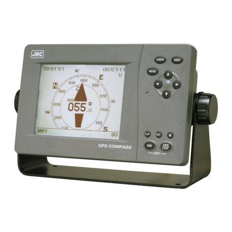
NWZ-4700 Display Unit
NNN-20 Sensor Unit
NNN-30 Sensor Unit

vii
CONTENTS
FOREWORD .......................................................................................I
BEFORE COMMENCING THE OPERATION.....................................II
PRECAUTIONS UPON THE OPERATION........................................III
APPEARANCE OF THE EQUIPMENT............................................. VI
SECTION 1 EQUIPMENT OVERVIEW.........................................1-1
1.1 FUNCTIONS ........................................................................................ 1-1
1.2 FEATURES .......................................................................................... 1-1
1.3 CONFIGURATION ............................................................................... 1-2
1.4 CONSTRUCTION ................................................................................ 1-3
1.5 SYSTEM DIAGRAM ............................................................................ 1-5
SECTION 2 INSTALLATION .........................................................2-1
2.1 SENSOR INSTALLATION.................................................................... 2-2
2.2 DISPLAY UNIT INSTALLATION........................................................... 2-8
2.3 CABLE CONNECTION ...................................................................... 2-10
SECTION 3 NAMES AND FUNCTIONS OF EACH UNIT.............3-1
3.1 NWZ-4700 DISPLAY UNIT ................................................................ 3-1
3.2 NNN-20/30 SENSOR UNIT ............................................................... 3-3
SECTION 4 DISPLAY ...................................................................4-1
4.1 DISPLAY SCREEN .............................................................................. 4-1
4.1.1 Compass Screen............................................................................ 4-2
4.1.2 Bow Heading Screen...................................................................... 4-3
4.1.3 Navigation Screen .......................................................................... 4-3
4.1.4 Turn Rate Screen ........................................................................... 4-4
4.1.5 Water Speed / Ground Speed Screen ............................................ 4-5
4.1.6 Configuration Screen...................................................................... 4-5
SECTION 5 OPERATION .............................................................5-1
5.1 MENU LIST.......................................................................................... 5-1
5.1.1 Menu List........................................................................................ 5-1
5.2 BASIC OPERATION ............................................................................ 5-3
5.2.1 Turning the Unit On ........................................................................ 5-3
5.2.1.1 Startup (Standard).................................................................... 5-3
5.2.1.2 Startup (Error-1)....................................................................... 5-4
5.2.1.3 Startup (Error-2)....................................................................... 5-4
5.2.1.4 Startup (Error-3)....................................................................... 5-5
5.2.2 Turning the Unit Off ........................................................................ 5-5
5.2.3 Adjusting the Backlight ................................................................... 5-6
5.2.4 Adjusting the Contrast .................................................................... 5-6
5.2.5 Stopping the Alarm Buzzer ............................................................. 5-7
5.2.6 Changing the Display ..................................................................... 5-7
5.2.7 Displaying Satellite Information ...................................................... 5-8

viii
5.2.8 Alarm History Display......................................................................5-9
5.3 MAIN MENU....................................................................................... 5-11
5.3.1 Display Settings ............................................................................5-12
5.3.1.1 Adjusting the Contrast............................................................5-13
5.3.1.2 Brightness Settings (DIMMER) ..............................................5-13
5.3.1.3 Click Sound Settings (CLICK SOUND) ..................................5-13
5.3.1.4 Display Reversing Setting (REVERSING MODE) .................. 5-14
5.3.2 Setting the Heading (HEADING)...................................................5-15
5.3.3 GPS Configuration (GPS) .............................................................5-17
5.3.3.1 Initial Settings (INITIALIZATION) ...........................................5-18
5.3.4 SBAS Settings (SBAS) .................................................................5-19
5.3.5 Beacon Settings (BEACON) .........................................................5-20
5.3.6 System Settings............................................................................5-21
5.3.7 Data I/O Settings (DATA I/O).........................................................5-22
5.3.8 Checking the Version .................................................................... 5-24
5.3.9 Others Settings .............................................................................5-25
5.3.10 Language Settings (LANGUAGE).................................................5-26
5.4 MAINTENANCE MENU......................................................................5-27
5.4.1 Antenna Check .............................................................................5-28
5.4.2 Input Check...................................................................................5-29
5.4.3 Self-Diagnosis (DIAGNOSIS) .......................................................5-30
5.4.4 Demo ............................................................................................5-33
5.4.5 Product Type Settings...................................................................5-34
5.4.6 Master Reset (RESET) .................................................................5-35
5.4.7 Software Update (SOFT UPDATE) ...............................................5-36
SECTION 6 MAINTENANCE AND INSPECTION ........................ 6-1
6.1 GENERAL MAINTENANCE AND INSPECTION ..................................6-1
6.2 ALARMS...............................................................................................6-2
6.3 TROUBLESHOOTING .........................................................................6-3
6.3.1 Troubleshooting ..............................................................................6-3
6.3.2 Repair Unit......................................................................................6-4
6.3.3 Regular Replacement Parts............................................................6-4
SECTION 7 AFTER-SALES SERVICE ........................................ 7-1
7.1 Warranty...............................................................................................7-1
7.2 Repair Parts Stocking Period................................................................7-1
7.3 When Requesting Service .................................................................... 7-1
7.4 Recommended Checks and Inspections ..............................................7-1
SECTION 8 DISPOSAL................................................................ 8-1
8.1 DISPOSAL OF THE EQUIPMENT .......................................................8-1
8.2 DISPOSAL OF USED BATTERIES ......................................................8-1
SECTION 9 SPECIFICATIONS.................................................... 9-1
9.1 DISPLAY UNIT (NWZ-4700).................................................................9-1
9.1.1 Panel...............................................................................................9-1
9.1.2 Power Supply..................................................................................9-1
9.1.3 Environment....................................................................................9-1
9.1.4 Dimensions and Mass.....................................................................9-1
ix
9.1.5 External Interfaces ......................................................................... 9-2
9.2 SENSOR UNIT (NNN-20/30) ............................................................... 9-3
9.2.1 Electrical Specifications .................................................................. 9-3
9.2.2 Environment ................................................................................... 9-3
9.2.3 Dimensions and Mass .................................................................... 9-3
APPENDIX................................................................... APPENDIX 1-1
Appendix 1 List of Geodetic Systems .......................................... Appendix 1-1
Appendix 2 Data Output Formats ................................................ Appendix 2-1
Appendix 3 Terminology .............................................................. Appendix 3-1

x

1-1
Section 1 Equipment Overview
1.1 Functions
This equipment determines the heading of a ship by measuring the orientation between two
antennas using the signal from GPS satellites.
The equipment not only determines the heading with high accuracy anywhere in the world and in
all weather conditions using the GPS satellites, but determines the position, course, and speed of
the ship. When the DGPS beacon receiver is connected, the accuracy of position fixing can be
enhanced by receiving correction data from the DGPS beacon station.
Since this equipment outputs the bearing information at high speed, if the unit is interfaced to a
JRC radar unit, it is possible to fully draw the capabilities of the radar and ARPA.
1.2 Features
●High accuracy and high stability (0.5 rms degree)
●Short setting time (less than 2 minutes at warm start fix)
●H
igh speed tracking response (Tracking rate of turn is 45 degree/sec)
●High visibility
5.7-inch FSTN LCD
●Many utility display modes (Compass rose graphics, ROT, NAV, GPS status, etc.)
●Easy installation
●Direct connection to the JRC radars

1-2
1.3 Configuration
Standard Configuration
JLR-20
No. Name Model/Code Q’ty Notes
1 Display Unit NWZ-4700 1
1-1 Power Cable CFQ-7257 1 2m / With fuse holder
1-2 Fuse MF60NR 250V 2 2 2Amps.
1-3 Clamp Filter TFC-23-11-14 1 5MBAT00002
1-4 Model Identification Plate MPNN44124 1
1-5 Installation Screws MPTG31659 1 4 tapping screws
1-6 Flush Mounting Screw Kit MPTG31962 1 4 screws
2 Sensor Unit NNN-20 1
2-1 Cable CFQ-7248 1 10m / 14 cores
2-2 Clamp Filter (Small) E04SR200935A 2
2-3 Clamp Filter (Large) E04SR301334 1
2-4 Bundling Band (Short) 1
2-5 Bundling Band (Long) 4
2-6 Self-bonding Tape 1
3 Instruction Manual (English) 7ZPNA4026 1
JLR-30
No. Name Model/Code Q’ty Notes
1 Display Unit NWZ-4700 1
1-1 Power Cable CFQ-7257 1 2m / With fuse holder
1-2 Fuse MF60NR 250V 2 2 2Amps.
1-3 Clamp Filter TFC-23-11-14 1 5MBAT00002
1-4 Model Identification Plate MPNN44124 1
1-5 Installation Screws MPTG31659 1 4 tapping screws
1-6 Flush Mounting Screw Kit MPTG31962 1 4 screws
2 Sensor Unit NNN-30 1
2-1 Cable CFQ-7248 1 10m / 14 cores
2-2 Clamp Filter (Small) E04SR200935A 2
2-3 Clamp Filter (Large) E04SR301334 1
2-4 Bundling Band (Short) 1
2-5 Bundling Band (Long) 4
2-6 Self-bonding Tape 1
3 Instruction Manual (English) 7ZPNA4026 1
Option
No. Name Model/Code Q’ty Notes
1 AC Power Rectifier NBA-3747 1 AC100 / 220V
2 Data Cable CFQ-5374 1
3m / 12 cores / Serial data
transmission
3 Data Cable CFQ-5404 1
3m / 14 cores / Dry contact signal
4 Extension Cable CFQ-7249 1
20m / 14 cores / For sensor extension
5 Beacon Connecting Cable CFQ-7250 1
For beacon receiver connection
6 Junction Box NQE-7720 1
14 connector / for sensor extension
7 GPS Repecon NQA-4115T 1 Digital/Synchronous Converter
8 DGPS Receiver JLR-4331 1 Integrates the DGPS beacon receiver
9 Mount MPBX44117 1 For NNN-20

1-3
1.4 Construction
•NWZ-4700 Display Unit
Dimensions: 267.4 x 162 x 85 mm
Mass: Approximately 2.3 kg

1-4
NNN-20/30 Sensor Unit
NNN-20
Dimensions: φ691 x 285mm
Mass: Approximately 6.2 kg
NNN-30
Dimensions: φ1152 x 286 mm
Mass: Approximately 9.5 kg

1-5
1.5 System Diagram
CFQ-7250
Data Cable
NWZ-4700
Display Unit
or
NBA-3747
Rectifier
DC 12/24V
AC 110/220V
DC24V
CFQ-7248
Data Cable (10m)
CFQ-7257
Power Cable
(2m)
NNN-30
Sensor Unit
DC12/24V
SENSOR
DATA
IN/OUT 1
DATA
IN/OUT 2
CONTACT
IN/OUT
NNN-20
Sensor Unit
CFQ-5374
Data Cable (3m)
IEC61162/NSK x 2
CFQ-5374
Data Cable (3m)
IEC61162/NSK x 3
CFQ-5404
Data Cable (3m)
Alarm x 2
Log Pulse x 1
JLR-4331
DGPS Receiver
JLR-20 JLR-30
Alarm System
External Buzzer
ECDIS
Radar
ECDIS/GPS Plotter
Tide Current Calculator
AIS
GPS Repecon
Power DC12V
(for beacon receiver)

1-6

2-1
Section 2 Installation
CAUTION
Please consult with JRC or an affiliate to perform installation. Installation by
unauthorized personnel may result in malfunction.

2-2
2.1 SENSOR INSTALLATION
CAUTION
Do not bend the cables included with this equipment excessively, or twist them or
subject them to other strong forces. Doing so may result in damage to the
interior or exterior of the cables, and may result in fire or electrocution.
Do not install the equipment in places subject to vibration or shock.
Doing so may result in the equipment failure due to reception problems.
This equipment uses GPS satellite signals to determine the bearing of the ship.
Install the sensor where there are no impediments to electrical signal reception,
and no signal reflection. If the sensor installation location environment is
unsatisfactory, ship bearing calculations is repeatedly interrupted.
If selection of the optimal installation location is difficult, and some concessions
must be made, place the sensor in the desired installation location and test the
acceptability of the sensor results before permanently installing the sensor.
Installing the sensor in an inappropriate location may result in decreased
accuracy and equipment failure.
Whenever possible, select a place having the following characteristics.
Out of the mast's
shadow.
(2 m or more
separation)
2 m or more outside of any radar beams.
Installation near radar antennas may result in multipath wave interference, which decreases the
accuracy of the equipment.
Whenever possible, keep the equipment out of any beams.
Away from the Inmarsat antenna by at least 5 m,
and out of the scope of the beam.
An open space which
allows uniform
reception of satellite
signals.
Inmarsat antenna
redome
Radar antenna
This manual suits for next models
1
Table of contents
Other JRC Marine GPS System manuals

JRC
JRC JUE-410F - User manual

JRC
JRC Alphatron LT-3100 Iridium User manual

JRC
JRC JLR-10 User manual

JRC
JRC J-Marine NeCST JAN-470 Series User manual

JRC
JRC JCY-1850 - User manual

JRC
JRC JUE-250 - User manual

JRC
JRC PRONAV V200S User manual

JRC
JRC JCY-1800 - User manual

JRC
JRC JHS-182 - User manual

JRC
JRC JLR-21 User manual