JUKI AE-200A User manual

ENGLISH
AE-200A
INSTRUCTION MANUAL

ii
CONTENTS
!. CAUTIONS BEFORE OPERATION ...............................................................................1
Precautions for use................................................................................................................................... 1
@. CONFIGURATION OF THE MACHINE..........................................................................2
#. OVERVIEW.....................................................................................................................3
1. Features ................................................................................................................................................. 3
2. Specications ........................................................................................................................................ 3
$. INSTALLATION ..............................................................................................................4
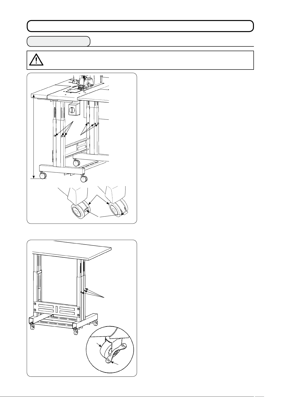
1. Table height............................................................................................................................................ 4
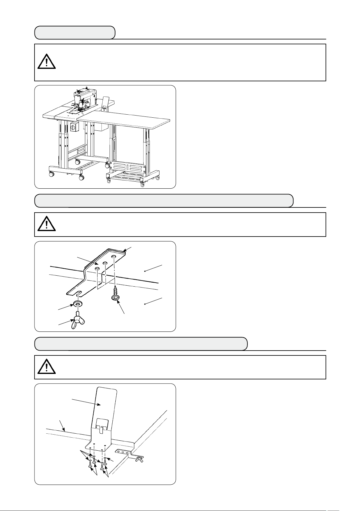
2. Auxiliary table ........................................................................................................................................ 5
3. Assembling the sewing machine table and auxiliary table ............................................................... 5
4. Installing the operation panel mounting plate.................................................................................... 5
5. Connecting the operation panel........................................................................................................... 6
6. Lubrication............................................................................................................................................. 7
7. Installing the thread stand.................................................................................................................... 7
8. Removing the covers ............................................................................................................................ 8
9. Threading the machine head................................................................................................................ 9
10. Adjusting the stitch length ............................................................................................................... 10
11. Fitting a needle .................................................................................................................................. 10
12. Loading the bobbin ........................................................................................................................... 11
13. Connecting and adjusting the air source........................................................................................ 11
%. INSTALLING THE OPTIONAL DEVICES ....................................................................12
1. Installing the 2-pedal unit ................................................................................................................... 12
2. Installing the stacker........................................................................................................................... 13
3. Installing and adjusting the bobbin winder ...................................................................................... 21
4. Assembling the thread breakage detecting device and setting of the operation panel ............... 23
5. Installing the bobbin thread remaining amount detecting device.................................................. 26
^. HOW TO USE THE OPERATION PANEL....................................................................33
1. Explanation about switches on the operation panel........................................................................ 33
2. Basic operation of the sewing machine............................................................................................ 35
3. Selecting a pattern .............................................................................................................................. 37
4. Winding a bobbin ................................................................................................................................ 38
5. Using the counter................................................................................................................................ 40
6. Changing the sewing data.................................................................................................................. 41
7. Using the initial value pattern ............................................................................................................ 42
8. Sewing data list ................................................................................................................................... 43
9. Copying a sewing pattern................................................................................................................... 50
10. Using the PATTERN REGISTRATION key........................................................................................ 51
11. Using the PARAMETER REGISTRATION key.................................................................................. 52
12. Performing the cycle sewing............................................................................................................ 53
13. Changing the memory switch data.................................................................................................. 55
14. List of memory switch data .............................................................................................................. 56
15. Setting the upper shirring................................................................................................................. 60
16. Setting the manipulator pressure .................................................................................................... 61
17. Using the teaching ............................................................................................................................ 62
18. Correcting the bottom feed amount readout potentiometer ......................................................... 64

iii
&. HANDLING AND ADJUSTING THE PARTS ...............................................................65
1. Adjusting the material slippage and manipulator pressure ............................................................ 65
2. Material auxiliary feed air blow .......................................................................................................... 69
3. Hand switch ......................................................................................................................................... 69
4. Material end sensor............................................................................................................................. 70
5. Adjusting the seam allowance ........................................................................................................... 70
6. Adjusting height of the upper manipulator roller............................................................................. 71
7. Pin tuck device S200 for AE-200A...................................................................................................... 72
*. ADJUSTING THE SEWING MACHINE........................................................................79
1. Adjusting the presser foot lifting lever.............................................................................................. 79
2. Thread tension..................................................................................................................................... 79
3. Thread take-up spring......................................................................................................................... 80
4. Presser foot lifting lever ..................................................................................................................... 80
5. Adjusting the presser foot pressure.................................................................................................. 80
6. Adjusting the walking foot pressure ................................................................................................. 81
7. Adjusting the thread take-up amount by thread take-up lever ....................................................... 81
8. How to adjust the amount of oil (oil splashes) in the hook............................................................. 82
9. Needle-to-hook relation ...................................................................................................................... 84
10. Counter knife ..................................................................................................................................... 85
11. Adjusting the feed timing.................................................................................................................. 85
12. Inclination of the feed dog................................................................................................................ 86
13. Height of the feed dog....................................................................................................................... 86
14. Lateral position of the feed dog....................................................................................................... 86
15. Precautions to be taken when correcting the longitudinal position of the walking foot............ 87
(. MAINTENANCE AND INSPECTION............................................................................88
1. Draining the lter regulator ................................................................................................................ 88
2. Cleaning the sensor ............................................................................................................................ 88
3. Lubricating the manipulator roller section ....................................................................................... 88
4. Replacing the fuse .............................................................................................................................. 89
5. List of optional parts for AE-200A...................................................................................................... 89
6. Error code list ...................................................................................................................................... 90
7. Setting data recording paper for AE-200A ........................................................................................ 93

− −
!. CAUTIONS BEFORE OPERATION
Following items have to be checked every working day before the operation of the machine
and before the start of work hours.
1. Ascertain that the oil pan is lled with the predetermined amount of oil.
2. Never operate the machine unless the oil pan has been lled up with oil.
3. Ascertain that the pressure gauge indicates the designated air pressure of 0.5 MPa.
* (This is necessary particularly when the compressor is stopped for a lunch break or the like.)
If the compressed air pressure is equal to or less than the designated value, troubles such
as interference between the parts can occur. It is therefore necessary to carefully check the
compressed air pressure.
4. Check whether the needle thread/bobbin thread need to be replenished.
5. To perform sewing immediately after turning ON the power switch, perform trial stitching rst,
then proceed with sewing of actual products after the test sewing.
6. In order to prevent the sensor from showing a detecting failure, be sure to clean thread waste
around the sensor using an air gun once or more times a day.
1. For a wider material, fold the material toward you and sew it while putting your hand on it. If you
don't guide the fabric by hand during sewing, the material may warp at the end of sewing.
2. When sewing some patterns, it is also necessary to put your hand on the material at the end of
sewing.
3. Setscrew for the presser bar base
) Never loosen setscrew 1 in the presser bar
base. If it is loosened, the walking foot move-
ment timing will change from the correct one.
2) When it is really necessary to loosen setscrew
1, it should be loosened when the walking foot
comes down to contact the throat plate surface.
1
Precautions for use

− 2 −
@. CONFIGURATION OF THE MACHINE
A Machine head (DLU-5498N-7)
B Start switch
C Operation panel
D Thread stand
E Upper manipulator
F Auxiliary table
G Sewing machine table
H Power switch
I Control box
J T stand
K Bobbin winder
L Air blow SC (Speed controller)
M T stand
N SS52 Stacker device (optional)
O Safety bar (optional)
P Air valve switch
Q Material end sensor
R 2-pedal unit (optional)
S Bobbin winder (optional)
T Air gun
H
A
D
B
C
I
N
O
F
G
J
M
E
P
Q
K
L
R
S
T

− −
#. OVERVIEW
Speed of stitch 200 to ,500 sti/min
2Stitch length 0 to 4 mm
Top feed amount 8 mm (Max.)
4 Presser foot lift (max.) 0 mm (Air-driven)
5 Seam allowance to 0 mm
6Needle to be used DBx #9 to #8 (Standard: #), 4 #75 (JE type)
7 Sewing condition
A) Curve sewing
B) Material size
C) Number of plies of materials
00 mm R or more
,500 (length) x 500 (width) or less
2 or
8 Power consumption 220VA
9 Power source -phase 200 to 240 V
Single-phase 200 to 240 V
0 Table height Adjustable between 820 to ,020 mm (Standard: 97 mm)
Sewing machine dimensions 2,75 (length) x ,200 (width) x ,50 (height) (mm)
Auxiliary table Standard: ,200 (length) x 550 (width) mm
2 Stacker SS52 Workpiece constant-retaining type
2-pedal unit Provided with the presser foot up/down switch and 2-step start switch; high/low
speed changeover
4 Weight 5 kg (when all options are installed)
5 Noise Declaration
- Equivalent continuous emission sound pressure level (LPA) at the workstation :
A-weighted value of 80 dB; (Includes KPA = 2.5 dB); according to ISO 082- C.6.
-ISO 204 GR2, at sewing cycle: 4 s ON and 7 s OFF.
This automatic machine consists of a bottom & variable top-feed, lockstitch machine with an automatic
thread trimmer, auto-lifter, upper and lower manipulators which control the material end with accuracy,
control box which controls the whole system, operation panel and auxiliary table.
(The sewing machine head is DLU-5498N-7 specically developed for AE-200A.)
Stacker device (SS52), 2-pedal unit, bobbin winder and bobbin thread remaining amount detecting device
are provided as options.
) Easy operation requiring no skill (Even an inexperienced operator is able to carry out work equivalent
to that by a skilled operator.)
2) Increased efciency is promised. (Re-arrangement of two pieces of fabric is required during manual
work. This machine eliminates such a re-arrangement, thereby shortening the time required for
sewing.)
) High-quality is ensured to improve reliability. (The sewing machine sews the materials with a consistent
seam allowance, thereby producing uniform products.)
4) The sewing machine permits the operator to operate it from its side face automatically or manually by
means of the pedal either standing or sitting.
5) The 2-pedal unit ensures accurate placement of the material on the sewing machine.
6) Seam allowance can be set in the range of and 0 mm.
7) Uneven material feed can be adjusted with ease.
2. Specications
1. Features

− 4 −
$. INSTALLATION
1. Table height
The table height can be adjusted in the range of 820
and ,020 mm. The standard height is 97 mm.
) Install the table stand on a at place.
2) Casters 1 are secured by lowering levers 2.
) Loosen six bolts 3 mounted on the right and left
legs of the table stand to adjust the table height.
917 mm (Standard)
1
2
3
[Table height of the auxiliary table]
) Install the table stand on a at place.
2) Casters 1 are secured by lowering the ON side
of levers 2.
) Loosen six bolts 3 mounted on the right and left
legs of the table stand to adjust the table height.
3
3
2
1
CAUTION :
Be sure not to lift the table by one worker but to lift it with four or more workers for
supporting each of the four corners of the table when adjusting the table height.

− 5 −
2. Auxiliary table
Adjust the auxiliary table height to the sewing
machine table height.
4. Installing the operation panel mounting plate
Install panel mounting plate 1 on auxiliary table 2
with four wood screws 3 and four washers 4.
3. Assembling the sewing machine table and auxiliary table
Fix spacer 1 and auxiliary table joint bracket 4 with
three wood screws 2 on auxiliary table 3. Then,
mount the joint bracket onto table 7 with thumb
screw 5 and washer 6.
1
2
3
4
5
6
7
CAUTION :
When installing the auxiliary table, the related parts may drop off or the table may fall causing
personal injury. To prevent this, be sure to carry out the installation of the auxiliary table with two
workers. One of them has to support the table. When installing the auxiliary table to the sewing
machine table, take care not to allow your hands, ngers, etc. to be caught between them.
CAUTION :
When using tools, take care to prevent parts from dropping resulting in personal injury.
Take also care not to get injured with the tool.
CAUTION :
When using tools, take care to prevent parts from dropping resulting in personal injury.
Take also care not to get injured with the tool.
1
3
2
3
4
4

− 6 −
5. Connecting the operation panel
Pass operation panel cord plug 1 through the hole
in operation panel mounting plate 2.
1
2
3
2
Place operation panel 3 on operation panel
mounting plate 2.
Pass operation panel cord plug 1 through the cord
through-hole in control box 4.
1
4
Open the cover of the control box. Insert operation
panel cord plug 1 into the main PCB connector
CN4.
1

− −
1. When operating a newly installed sew-
ing machine or a machine which has
not been used a long period, be sure
to run the sewing machine for approxi-
mately 10 minutes for the purpose of
break-in using the bobbin winding key
mounted on the operation panel.
2. Be sure to use JUKI's genuine oil. If
any other oil is used, a trouble may be
caused.
6. Lubrication
Before operating the sewing machine
1) Put magnet 1 supplied with the unit in the
waste oil screw section.
2) Fill oil pan 2 with JUKI New Defrix Oil No. 1 un-
til HIGH mark A is reached.
3) When the oil level lowers below LOW mark B,
re-ll the oil pan with the specied oil.
4) When you operate the sewing machine after lu-
brication, you will see splashing of oil through oil
sight window 3 if the lubrication is normal.
5) Note that the amount of the splashing oil does
not represent the amount of oil in the oil pan.
7. Installing the thread stand
1) Assemble the thread stand unit. Then, insert the
assembled thread stand into the hole in the ta-
ble.
2) Tighten locknut 1 to such an extent that the
thread stand does not uctuate.
1
CAUTION :
When tilting or re-raising the sewing machine, take care not to allow your ngers or any
other part of your body to be caught.
1
A
B
3
2

− 8 −
8. Removing the covers
) Remove upper manipulator roller cover 1.
2) Putting your finger on lever 2, lift the lever to
release the upper manipulator 4.
) Rotate the upper manipulator to remove lower
manipulator roller cover 3.
After the removal of the upper and lower manip-After the removal of the upper and lower manip-
ulator roller covers, replace the upper manipula-
tor 4 back to its position.
1
2
3
4
If you press the upper manipulator
downward 6while rotating it, the under-
side of sensor 7can come in contact
with the machine table and the top plate
of the bed, resulting a failure.
4) To rotate upper manipulator 4 back to its home
position, rotate upper manipulator 4 until it
comes in contact with stopper screw 5, then
press upper manipulator 4 downward 6.
5
76

− 9 −
CAUTION :
To avoid possible accident due to abrupt start of the sewing machine, turn off the power to
the machine beforehand.
9. Threading the machine head
Thread the machine head in the order as illustrated in the gure.
Drive thread guide pin Ain the hole on the top surface of the machine arm before threading it.
2
1
4
3
6
5
8
7
9
!0
!1
!2
!3
A

− 0 −
1
A
10. Adjusting the stitch length
2
1
A
11. Fitting a needle
* Turn off the power to the motor.
Use DBx (DPx for the DP type sewing machine)
needle.
) Turn the handwheel to move the needle bar up
to its highest position.
2) Loosen needle clamping screw 2. Hold needle
1 so that its scarf A faces exactly to the right B.
) Insert the needle fully into the hole in the needle
bar in the direction of the arrow until it goes no
further.
4) Securely tighten needle clamping screw 2.
5) Check to be sure that slot C in the needle faces
just left D direction.
2
Bottom feed length
) Turn stitch dial 1 in the direction of the arrow
until a desired numeral is aligned with marker
dot A on the machine arm.
2) The numerals are given in millimeters (mm).
) To change the feed length from a larger value to
a smaller value, turn stitch dial 1 while pressing
feed lever 2 in the direction of the arrow.
Top feed length
Refer to "^-18. Correcting the bottom feed
amount readout potentiometer" on page 64 for
how to adjust the top feed length.
B
D
C
CAUTION :
To avoid possible accident due to abrupt start of the sewing machine, turn off the power to
the machine beforehand.

− 11 −
1
3
12. Loading the bobbin
2
1) Holding the bobbin so that thread inside the
bobbin spins clockwise, put it in the bobbin
case.
2) Pass the thread through slot 1 in the bobbin
case. Draw the thread in toward thread open-
ing 2, and it will appear from thread opening 2
through under the tension spring.
3) Check to be sure that the bobbin rotates in the
direction of the arrow when drawing bobbin
thread 3.
1
4
13. Connecting and adjusting the air source
2
1) Insert air hose 1 into one-touch utility joint 2
supplied with the unit.
2) Insert one-touch utility joint 2 into joint 3 until it
clicks.
3) Adjust the air pressure to 0.5 MPa (5 kgf/cm2).
If the pressure is inadequate, lift knob 4 and
turn it clockwise (in direction C).
If the pressure is too high, turn the knob coun-
terclockwise (in direction D).
When the air presser is set at 0.5 MPa (5 kgf/
cm2), lower knob 4 and x it.
3
C
D
CAUTION :
To avoid possible accident due to abrupt start of the sewing machine, turn off the power
to the machine and make sure that the machine does not run even when you depress the
start pedal.

%. INSTALLING THE OPTIONAL DEVICES
1. Installing the 2-pedal unit
CAUTION :
Be sure to turn off the power to the sewing machine before installation of the 2-pedal unit
in order to protect the electric parts from being damaged.
2
1.
3.
2
1
3

2. Installing the stacker
CAUTION :
Be sure to turn off the power to the sewing machine before installation of the 2-pedal unit
in order to protect the electric parts from being damaged.
Stacker solenoid valve
1Left pedal, 2-step pedal (manual start, pause)
2Right pedal (changeover of speed between
high and low)
1 2

132.
45
6
74.
2
1
6
3
5
4
7
!0 8
9.
9
8!0
!1
!2!3
!4!5
!1
!2 !3
!4!5.

!6!7!8
!1 !6 !7
!8.
!9
8!2!5
Place inside
!9
8
@0
@2
@1
@1
@0

@2
Presser foot lifting solenoid valve
Presser foot lifting lever
Workpiece
holder
Workpiece
holder
solenoid valve
Stacker solenoid valve
Air gun
Disconnect the pipe
and connect to Y joint
Connect to 18
Air piping diagram
BOX side
PCB

1
・Adjusting the workpiece holder
1
A
2
B
A
B
Clockwise Counterclockwise
2
CAUTION :
To avoid possible accident due to abrupt start of the sewing machine, turn off the power
to the machine and make sure that the machine does not run even when you depress the
start pedal. In addition, take care not to allow your ngers to be caught under the stacker
workpiece holder since it comes down.
Table of contents
Other JUKI Sewing Machine manuals

JUKI
JUKI LU-1560N User manual

JUKI
JUKI LU-1510N-7 User manual

JUKI
JUKI MS-1261 User manual

JUKI
JUKI LBH-772NV-1 User manual

JUKI
JUKI MO-6900R Series User manual

JUKI
JUKI AMB-289/IP-420 User manual

JUKI
JUKI AC-172NN-1790 User manual

JUKI
JUKI LZ-271 User manual

JUKI
JUKI AMB-289 User manual

JUKI
JUKI DX-2000QVP User manual

JUKI
JUKI MF-7700 Series Quick start guide

JUKI
JUKI DSC-244 User manual

JUKI
JUKI TL-98P perfection User manual

JUKI
JUKI MO-613V User manual

JUKI
JUKI UnionSpecial 35800BLWG Setup guide

JUKI
JUKI TL Series User manual

JUKI
JUKI DLN-9010A User manual

JUKI
JUKI IP-100A Quick start guide

JUKI
JUKI AMS-210E Series Quick start guide

JUKI
JUKI DDL-5550N-7 User manual