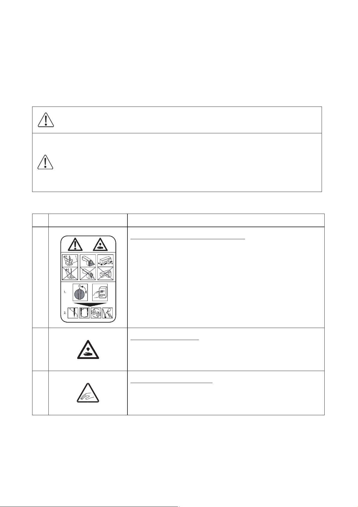
JUKI PLK-J6040R3 User manual

INDUSTRIAL SEWING MACHINE
MODEL
PLK-J6040R3
TECHNICAL MANUAL
SEWING MACHINE HEAD
A181E048P01

FOR SAFE USE
Before the installation, operation, and inspection for this product, read the “FOR SAFE USE” and the
technical manuals carefully. Also read the other technical manuals, “Control Unit” and “Operation Panel”
describing some instructions, which are not in this manual, and use the sewing machine properly.
SAFETY INDICATIONS
DANGER
Indicates that incorrect handling may cause hazardous conditions, resulting
in death or severe injury.
CAUTION
Indicates that incorrect handling may cause hazardous conditions, resulting
in medium or slight personal injury or physical damage. Note that CAUTION
level may lead to a serious consequence according to the circumstances.
Always follow the instructions of both levels because they are important to
personal safety.
CAUTION INDICATIONS
No.
Caution indication
Description
1
Prec
aution for sewing machine operation:
Indicates that removing the safety and operating
the sewing
machine for some other purposes with power-on
are prohibited.
zPlease do not operate the sewing machine
without
protective
equipment such as a needle guard, an eye guard,
a belt cover or the others.
zPlease turn off the
power switch when threading, changing
a needle and a bobbin, cleaning, and lubricating.
2
Caution
for fingers injury:
Indicates a possibility of fingers (hands) injury in a certain
condition.
3
Caution
for squeezing fingers:
Indicates a possibility of squeezing fingers in a certain
condition.

SAFETY PRECAUTIONS
DANGER
To prevent from receiving an electric shock, always turn off a power switch
and
unplug power supply
when opening a control
box, and then open after ten minutes passes.
CAUTION
USAGE ENVIRONMENT
Please do not operate the sewing machine under the following conditions.
(1)
In the ambient temperature of 35 degrees (95°F) or more than 35 degrees, or the
ambient
temperature of 5 degrees or less than 5 degrees (41°F).
(2)
In the ambient temperature of 55 degrees (131°F) or more than 55 degrees, or the
ambient
temperature of -10 degrees or less than -10 degrees (18°F) during transportation.
(3)
In the relative humidity exceeding 85% or less than 45%.
(4)
In the open-air place or the location that receives direct sunlight.
(5)
In the place near heat sources such as heating devices.
(6)
In the atmosphere filled with dust, explosive gas, or corrosive gas.
(7)
In the place where the
fluctuation in the power voltage of 10% or more than 10%, or the power
voltage of -10% or less than -10% of the fixed power voltage.
(8)
In the place where the power source cannot supply enough voltage to keep the motor running.
(9)
In the place filled with strong electric noises such as high-frequency welders.
INSTALLATION
(1)
Please have some specialists, who have enough experience for the sewing machine installations,
install the sewing machine.
(2)
Please have a qualified electrician perform necessary electric wiring.
(3)
Please do not operate until the sewing machine is repaired when any damage or fault is found on
the sewing machine at the installation.
(4)
Please do not refurbish the sewing machine.
(5)
The sewing machine is heavy. For the safety, please make sure to
install the sewing machine head
by more than one person.
(6)
Please make sure to fit the safety protective equipment (the motor cover or the others) and the
accessory protective equipment (the eye guard) that removed temporarily for installation.

SEWING
(1)
Please make sure to turn the power switch off before installing or replacing needles.
(2)
Please pay attention for the fingers not to be injured by the needle point.
(3)
Please make sure to turn power switch off before lubricating.
(4)
Please pay attention that oil does not get on your skin or in your eyes as it
may cause an
inflammation.
(5)
Please make sure to keep oil out of the reach of children who may drink oil by mistake.
(6)
Please make sure to turn the power switch off before threading a needle.
(7)
Before starting the sewing, please make sure the position and the function of the halt switch.
(8)
Please do not touch the operating parts during sewing operation.
(9)
It is very danger
ous to operate the sewing machine without safety guards (eye guards, belt covers,
link covers, finger guards or the others).
Please make sure to operate the sewing machine with safety guards.
(10) Please make sure to turn the power switch off when stopping
the sewing machine temporarily.
ADJUSTMENT
(1) Please make sure to turn the power switch off before adjusting the sewing machine.
(2) If the adjustment is required
while
the power switch on, do not step on the foot switch by mistake.
(3) Please be careful not to be injured by a sharp part such as the needle and the shuttle hook point.
(4) Please make sure to put the safety guards (eye guards, belt guards, link covers, and finger guards
or the others) back on the initial position after the sewing machine adjustment.

CONTENTS
1. STRUCTURE OF THE SEWING MACHINE····································
1
2. SPECIFICATIONS·····································································
2
3. INSTALLATION········································································
3
3-1. Installation of the foot switch···································································
3-2. Connection of the air tube·······································································
3-3. Installation of the thread stand·································································
3-4. Installation of the eye guard····································································
3-5. Installation of the rubber cushion······························································
3
4
4
5
5
4. LUBRICATION·········································································
6
4-1. Filling the oil tank··················································································
6
5. PROPER OPERATION······························································
7
5-1. Installation of the needles·······································································
5-2. Threading the needle thread···································································
5-3. Winding the bobbin thread······································································
5-4. How to opening the bobbin access door·····················································
5-5. Setting the bobbin·················································································
5-6. Setting the bobbin case··········································································
5-7. How to operating the jig eject system························································
5-8. Operation of the halt switch·····································································
5-9. Adjustment of the thread tension······························································
5-10. Adjustment of upper thread tension·························································
7
8
9
10
11
11
12
13
14
14
6. S
TANDARD ADJUSTMENT···························
·····························
15
6-1. Adjustment of the needle bar position·······················································
6-2. Adjustment of the position between the needle and the rotating hook·············
6-2-1. Adjustment of the clearance between the hook point and the needle·········
6-2-2. Adjustment of the timing between hook and needle motion ····················
6-3. Adjustment of the hook positioner’s position··············································
6-4. Adjustment of the oil lubrication······························································
6-5. Setting of the pressor foot movement·······················································
6-6. Adjustment of the wiper·········································································
15
16
16
19
22
23
24
24

6-7. Adjustment of the thread take up spring····················································
6-7-1. Adjusting movable range of the thread take up spring····························
6-7-2. Adjusting intensity of the thread take up spring·····································
6-8. Adjustment of the thread tail after the trimming···········································
6-9 Adjustment of the air pressure·································································
25
25
25
26
26
7.
VARIOS ADJUSTMENT······································
·······················
27
7-1. How to exchanging the tension spring of the needle thread tensioner unit·······
7-2. Adjustment of the detector position of the presser foot unit···························
7-3. How to replace with a special pressor foot················································
7-4. Adjustment of the pressor foot holder position············································
7-5. How to changing the thread take up lever stroke········································
7-6. Adjustment of the thread trimmer····························································
7-6-1. Adjustment of the movable knife··························································
7-6-2. Adjustment of meshing pressure between the movable knife and the fixed
knife ····························································································
7-6-3. Adjustment of the holding pressure of the bobbin thread··························
7-6-4. Adjustment of the trimmer cam detector position····································
7-7. How to remove the XY cover··································································
7-8. Adjustment of the XY table detector·························································
7-8-1. Adjustment of X direction···································································
7-8-2. Adjustment of Y direction···································································
7-9. Adjustment of the Y timing belt tension·····················································
27
29
32
35
36
38
38
40
41
42
43
44
45
46
47
8. MAINTENANCE·······································································
48
8-1. Cleaning····························································································
8-2. Greasing····························································································
8-3. Disposing of oil waste···········································································
48
48
50
9. TROUBLESHOOTING·······························································
51
10. APPENDIX
10-1. The positional relationship between the sewing area and jig eject system
10-2. Air piping drawing

-1-
1. STRUCTURE OF THE SEWING MACHINE
PLK-J6040R3 industrial sewing machine consists of the following main parts.
<1>: Sewing machine head <2>: Halt switch <3>: Control box <4>: Operation panel
<5>: Work holder switch <6>: Start switch <7>: Thread stand <8>: Sewing machine table
<1>
<2>
<3>
<4>
<5>
<
<6>
<7>
<8>

- 2 -
2. SPECIFICATIONS
Model
PLK
-J6040R3
Stitch type
Single needle lock stitch
Hook
Triple
size rotating hook
Class of needle
DPX17#
21
Sewing area
X
-direction (left/right) 600 mm
Y
-direction (front / back) 400 mm
Maximum sewing speed
*1
2,
500rpm (Continuous feeding) 2,300rpm (M3 feeding)
Maximum sewing speed
10 speed levels in 200 rpm to 2,300 rpm (
M3 feeding)
Stitch
length
0.1 to 20.0 mm
(min. resolution 0.1 mm)
Maximum number of needles
20,000 per pattern
Storable sewing data item
9,000
patterns*2
Data memory
USB memory
Type of motor (Needle side)
750W direct servo motor
Type of motor (Hook side)
40
0W direct servo motor
Work holder
Jig eject system
N
eedle bar stroke
42.1
mm
Thread take up lever stroke
77.1 mm (factory default setting) / 74.1 mm
Thread take up lever stroke manual change system
Presser foot drive
Direct drive by stepping motor
P
resser foot lift
18.0
mm (max. 24.0 mm) Variable in 0.1 mm step
Presser foot stroke
*3
Digi
tal adjustment stroke: 0.1 to 10.0 mm
Upper thread tensioner
Manual / automatic / Setting on pattern (switchover)
Wiper
system
Back to front wiping system
Oil
lubrication
Spray method: Spray time adjustment
Operation panel
6.5
-inch color LCD touch panel with USB port
External device I/F
USB port, Terminal I/O: 16 input, 16 output
Thread trimmer system
Horizontal engagement with fixed knife and
movable knife
Machine dimensions
(W)x(L)x(H)
1,350mm x 1,570mm x1,205mm
Weight
44
0kg
Power
In 200V to 240V single
-phase or three-phase
*1: Sewing speed may be limited by the operation or sewing condition.
*2: The max. patterns may be limited depending on the number of stitches of each pattern in the memory.
*3: Standard value is 8.0 mm.

-3-
3. INSTALLATION
CAUTION
(1) Please have some specialists, who have enough experience for the sewing machine installations,
install the sewing machine.
(2)
Please have a Qualified Electrician perform necessary electric wiring.
(3) Please do not operate until the sewing machine is repaired when any damage or fault is found on
the sewing machine at the installation.
(4) Please do not refurbish the sewing machine.
3-1. Installation of the foot switch
Connect the foot switch to the connector CON L. The foot switch is enclosed in the accessory box.
NOTE Refer to the instructions in the paragraph “[4] Name of each part, wiring and grounding” in the
CONTROL UNIT technical manual.
CON L Foot switch

-4-
3-2. Connection of the air tube
Insert the one end of the air tube (8mm Diameter) into the intake air fitting (No.3) of the filter regulator
(No.2) then, join the other end of the air tube with the suitable air coupling to be adopted with the air supply
source provided in your factory. One of the air couplings (No.4) is enclosed in the accessory box.
3-3. Installation of the thread stand
(1) Assemble the parts of the thread stand as shown on the figure.
(2) Fit the thread stand into the hole at the far right on the machine arm with the nut (No.14) and the washer
(No.12) and cushion (No.13).
<1>: Air tube (8mm Diameter)
<2>: Filter regulator
<3>: Intake air fitting
<4>: Air coupling
<4>
<3>
<1>
<2>
<1>: Upper column pipe
<2>: Lower column pipe
<3>: Spool stand base
<4>: Spool mat
<5>: Spool holder
<6>: Spool shaft
<7>: Spring washer
<8>: Nut
<9>: Thread hunger
<10>: Spool holder
<11>: Column joint
<12>: Washer
<13>: Cushion
<14>: Nut
<15>: Bracket (large)
<16>: Bracket (small)
<17>: Holder
<18>: Thread guide
<1>
<12>
<3>
<4>
<6>
<7>
>
<8>
<9>
<1
<2>
<10>
<11>
<5>
<14>
<13>
<12>
<17>
<16>
<18>
<15>

-5-
3-4. Installation of the eye guard
(1) Mount the eye guard (No.1) with screw (No.2) to sewing machine head.
3-5. Installation of the rubber cushion
(1) Screw the adjust foot (No.2) in the direction of “a” arrow and locate the rubber cushion (No.1) between
the adjust foot and floor which included in accessory box. For the other three rubber cushions, the
procedure is same.
(2) Screw the adjust foot (No.2) in the direction of “b” arrow and adjust the adjust foot height so that the
each hour caster (No.3) is to be raised from the floor by several millimeters. After adjustment please
check if there is no inclination about the machine table.
<1>: Eye guard unit
<2>: Screw
<1>
<2>
b
a
<3>
<1>: Rubber cushion
<2>:
Adjust foot
<3>: Caster
<1>
<2>

-6-
4. LUBRICATION
CAUTION
(1) Please make sure to turn power switch off before lubricating.
(2) Please pay attention that
oil does not get on your skin or in your eyes as it
may cause an
inflammation.
(3) Please make sure to keep oil out of the reach of children who may drink oil by mistake.
NOTICE Please make sure to lubricate when operating for the first time after the installation. Also, please
make sure to check the amount of oil when the machine has not been used for a long time.
4-1. Filling the oil tank
Pour the oil through the oil hole (No.1) to the oil tank (No.2) on the machine arm. Pour the oil through
the oil hole (No.3) which has machine table to the oil tank (No.4). Please fill with the oil over level
mark (No.5) of the oil tank.
<3>
<4>
<5>
<2>
<1>
<5>
<
5
<1>: Oil hole
<2>: Oil tank
<
5>: Level mark
<3>: Oil hole
<
4>: Oil tank
<
5>: Level mark

-7-
5. PROPER OPERATION
5-1. Installation of the needle
CAUTION
(1) Please make sure to turn the power switch off before installing or replacing needles.
(2) Please pay attention for the fingers not to be injured by the needle point.
(1) Loosen the set screw (No.1) then, insert a new needle (No.2) until the needle head is reached the end
of the hole of the needle bar (No.3).
(2) Tighten the set screw (No.1) with facing the needle groove (No.4) to the front.
<3>
<1>
<2>
<4>
<1>: Set screw
<2>: Needle
<3>: Needle bar
<4>: Needle groove

-8-
5-2. Threading the needle thread
CAUTION
(1) Please turn the power switch off when threading a needle.
(1) Thread the needle thread as shown on the figure.

-9-
5-3. Winding the bobbin thread
CAUTION
(1) Please do not touch the rotating part during winding thread. Doing so may cause injury and/or the
machine failure.
NOTICE Please make sure to pull the upper thread out of the needle before winding the bobbin thread.
(1) Route the thread as shown in the below figure then, wind the thread to the bobbin (No.1) in the direction
of “a” arrow several times. Then fit the bobbin to the bobbin winder (No.2) and push in the bobbin
presser arm (No.3).
(2) With the machine in the Bobbin Wind Mode, step on the work holder foot switch first and then the start
switch second so that the thread continues winding to the bobbin while the start switch is stepped on.
(3) When the bobbin finishes winding a certain amount (80 to 90 % of the outside diameter of bobbin) of
thread, the bobbin presser arm is returned to the initial position. Adjust the amount of the winding
thread with the subsidiary arm (No.4).
(4) To wind the bobbin thread during the sewing operation, carry out the procedure (1) above then, the
bobbin winding is performed automatically.
For the bobbin winding mode, refer to the instructions in the paragraph “[3] Explanations of basic
screen, icons and operation “6. The Bobbin Winding screen” is explained below” in the
OPERATION PANEL technical manual.
<1>: Bobbin <2>: Bobbin winder <3>: Bobbin presser arm <4>: Subsidiary arm
a
<1>
<3>
<4>
<2>

- 10 -
5-4.How to opening the bobbin access door
When exchanging the bobbin, please open the bobbin access door (No.1) referring the following paragraph.
The bobbin access door has center of the machine table.
(1) Turn the opening switch (No.2) in the direction of the arrow which has front lower side of the table. The
bobbin access door opens when opening switch (No.2) becomes state in <B> showing in below figure.
(2) When closing the bobbin access door (No.1), turn the opening switch (No.2) in the opposite direction
from state in <B>.
NOTE When start the sewing unless the bobbin access door (No.1) is opened, the start prohibition signal
is valid.
<A>: Door close
<B>: Door open
<2>
<1>
<1>: Bobbin access door <2>: Opening switch

-11-
5-5. Setting the bobbin
(1) Set the bobbin (No.2) into the bobbin case (No.1).
(2) Pull the bobbin thread (No.3) into the slit (No.4) and pass through the thread hole (No.5) and thread
guide (No.6).
(3) At this time, pull the bobbin thread (No.3) then, check with the bobbin (No.2) if it is rotated to the
arrow direction. If it is not, set the bobbin (No.2) into the bobbin case (No.1) over again to get the
proper rotation.
5-6. Setting the bobbin case
(1) Pull the bobbin thread about 50mm out of the thread hole of the bobbin case (No.1).
(2) Open the bobbin access door.
(3) Open the bobbin case latch (No.2) and hold it then, fit it securely in the inner hook (No.3).
<1>: Bobbin case <2>: Bobbin <3>: Thread <4>: Bobbin case slit
<5>: Bobbin case thread hole
<6>: Thread guide
<4>
<2>
<3>
<5>
<1>
<1>
<3>
<6>
<3>
<1>
᳧
᳧
᳧
<2>
<1>
<1>: Bobbin case <2>: Bobbin case latch <3>: Inner hook

- 12 -
5-7.How to operating the jig eject system
(1) Prepare the type of the work holder for jig eject system, and install the cassette jig right (No.1) and
cassette jig left (No.2) which are enclosed in accessory box.
NOTE For more information concerning about dimension, please refer to the last chapter <10-1.>.
(2) Install the cassette jig right (No.1) and cassette jig left (No.2) to the inmost part of the each jig eject
system (No.3).
(3) Step on the work holder (black colored) foot pedal. The work holder become fixed when both of locate
pin (No.4) which has each jig eject system actuated. Please make sure if the work holder is fixed
securely after step on the foot pedal. The work holder is not fixed due to the insufficient actuation of
locate pin (No.4) when either or both cassette jig are not installed enough.
NOTE Please make sure if the bottom surface of cassette jig (A) and lower plate (No.5) are in same level.
If different, loosen the each four of Jig eject system install screws (No.6) and adjust the jig eject system
(No.3) height.
NOTICE Please note that the lower plate (No.5) does not touch directly to the slide plate.
<1>: cassette jig right <2>: cassette jig left <3>: Jig eject system
<6>
: Jig eject system install screw
<4>
<3>
<5>
<A>
<3>: Jig eject system
<4>: Locate pin
<5>: Lower plate
<A>: Bottom surface of cassette jig
<2>
<1>
<1
>
”R” marking
<
”L” marking
<6>
<6>
<3>
<3>

- 13 -
5-8. Operation of the halt switch
(1) If accidents such as a thread breakage, needle breakage and others happened during the sewing,
press the halt switch immediately. The sewing machine stops instantly.
(2) To cancel the halt state, press the halt switch again.
(3) When continuing sewing, step on the grey foot switch to restart at the halted position. (Press the jogging
in forward/reverse direction icon so that the sewing start position will move.)
(4) To cancel sewing, press the home position return icon .
<1>: Halt switch
<1>

- 14 -
5-9. Adjustment of the thread tension
(1) Adjust the bobbin thread tension with the thread tension adjusting screw (No.2) on the bobbin case
(No.1). The thread tension become loose if turn the thread tension adjusting screw (No.2) to the
counterclockwise, and the thread tension becomes tight if turn it to the clockwise.
5-10. Adjustment of upper thread tension
Adjust the upper thread tension corresponding to the bobbin thread tension. The upper thread tension
becomes tight when tightening the thread tension adjusting nut (No.1) clockwise, and the upper thread
tension becomes loose when loosening the thread tension adjusting nut counterclockwise.
NOTE It is possible to adjust the upper thread tension automatically. Please refer to the instructions
OPERATION PANEL technical manual concerning about [Digital tension].
<1>: Thread tension adjusting nut
<1>
<
<1>: Bobbin case
<2>: Adjusting screw
<1>
<2>
Table of contents
Other JUKI Sewing Machine manuals

JUKI
JUKI LBH-1702 User manual

JUKI
JUKI HZL-X Series User manual

JUKI
JUKI LK-1930 User manual

JUKI
JUKI DDL-9000B-SS User manual

JUKI
JUKI DLU-5494N-7 User manual

JUKI
JUKI LU-2216N-7 User manual

JUKI
JUKI DLM-5200 User manual

JUKI
JUKI Exceed F-300 Installation guide

JUKI
JUKI SC-500 Quick start guide

JUKI
JUKI DDL-5550N User manual

JUKI
JUKI MS-1190 User manual

JUKI
JUKI PS-800SB-2850 Series User manual

JUKI
JUKI LK-980 Series Quick start guide

JUKI
JUKI UnionSpecial 35800BLWG Setup guide

JUKI
JUKI MO-644D User manual

JUKI
JUKI AMS-210E Series Quick start guide

JUKI
JUKI SC-910N Quick start guide

JUKI
JUKI HZL-E70 User manual

JUKI
JUKI DDL-8700B-7 User manual

JUKI
JUKI DX-4000QVP User manual