JUKI LK-1900A User manual

E-No.02
40012747
R
INSTRUCTION MANUAL
Computer-controlled, High-speed,
Bartacking Machine
NOTE : Read safety instructions carefully and understand them before using.
Retain this Instruction Manual for future reference.
LK-1900A
LK-1901A LK-1902A
LK-1903A LK-1903A-305

Please do not hesitate to contact our distributors or agents in your area for further information when necessary.
*The description covered in this instruction manual is subject to change for improvement of the
commodity without notice.
04 · 03 Printed in Japan (E)
R
INTERNATIONAL SALES H.Q.
8-2-1, KOKURYO-CHO,
CHOFU-SHI, TOKYO 182-8655, JAPAN
PHONE : (81)3-3430-4001 to 4005
FAX : (81)3-3430-4909 • 4914 • 4984
TELEX : J22967
Copyright 狡
2003-2004 JUKI CORPORATION.
All rights reserved throughout the world.

i
IMPORTANT SAFETY INSTRUCTIONS
Putting sewing systems into operation is prohibited until it has been ascertained that the sewing systems in
which these sewing machines will be built into, have conformed with the safety regulations in your country.
Technical service for those sewing systems is also prohibited.
1. Observe the basic safety measures, including, but not limited to the following ones, whenever you use the
machine.
2. Read all the instructions, including, but not limited to this Instruction Manual before you use the machine. In
addition, keep this Instruction Manual so that you may read it at anytime when necessary.
3. Use the machine after it has been ascertained that it conforms with safety rules/standards valid in your
country.
4. All safety devices must be in position when the machine is ready for work or in operation. The operation
without the specified safety devices is not allowed.
5. This machine shall be operated by appropriately-trained operators.
6. For your personal protection, we recommend that you wear safety glasses.
7. For the following, turn off the power switch or disconnect the power plug of the machine from the
receptacle.
7-1 For threading needle(s), looper, spreader etc. and replacing bobbin.
7-2 For replacing part(s) of needle, presser foot, throat plate, looper, spreader, feed dog, needle guard, folder,
cloth guide etc.
7-3 For repair work.
7-4 When leaving the working place or when the working place is unattended.
7-5 When using clutch motors without applying brake, it has to be waited until the motor stopped totally.
8. If you should allow oil, grease, etc. used with the machine and devices to come in contact with your eyes or
skin or swallow any of such liquid by mistake, immediately wash the contacted areas and consult a medical
doctor.
9. Tampering with the live parts and devices, regardless of whether the machine is powered, is prohibited.
10. Repair, remodeling and adjustment works must only be done by appropriately trained technicians or
specially skilled personnel. Only spare parts designated by JUKI can be used for repairs.
11. General maintenance and inspection works have to be done by appropriately trained personnel.
12. Repair and maintenance works of electrical components shall be conducted by qualified electric
technicians or under the audit and guidance of specially skilled personnel.
Whenever you find a failure of any of electrical components, immediately stop the machine.
13. Before making repair and maintenance works on the machine equipped with pneumatic parts such as an air
cylinder, the air compressor has to be detached from the machine and the compressed air supply has to be
cut off. Existing residual air pressure after disconnecting the air compressor from the machine has to be
expelled. Exceptions to this are only adjustments and performance checks done by appropriately trained
technicians or specially skilled personnel.
14. Periodically clean the machine throughout the period of use.
15. Grounding the machine is always necessary for the normal operation of the machine. The machine has to
be operated in an environment that is free from strong noise sources such as high-frequency welder.
16. An appropriate power plug has to be attached to the machine by electric technicians. Power plug has to be
connected to a grounded receptacle.
17. The machine is only allowed to be used for the purpose intended. Other used are not allowed.
18. Remodel or modify the machine in accordance with the safety rules/standards while taking all the effective
safety measures. JUKI assumes no responsibility for damage caused by remodeling or modification of the
machine.
19. Warning hints are marked with the two shown symbols.
Danger of injury to operator or service staff
Items requiring special attention

ii
FOR SAFE OPERATION
1. To avoid electrical shock hazards, neither open the cover of the electrical box for
the motor nor touch the components mounted inside the electrical box.
2. After changing the pattern, make sure the needle entry point. If the pattern is protruded
from the work clamp feet, the needle will interfere with the work clamp feet during
sewing, and it is dangerous due to the needle breakage or the like.
3. Do not turn OFF the power in a state that the needle is lowered. Wiper may break the
needle.
1. When nothing is displayed in the operation panel even when the power switch is
turned ON, turn OFF the power switch and check the voltage and the type of the
power source.
2. So as to prevent possible accidents caused by abrupt start of the sewing machine,
depress the start switch after ascertaining that there is no interfering thing under
the needle when winding the bobbin thread.
3. When turning OFF the power switch, turning ON the ready switch or turning ON the
work clamp foot switch, the work clamp feet automatically come down. So, never
place your fingers under the work clamp feet to prevent possible accidents caused
by abrupt start of the sewing machine. During operation, be careful not to allow your
fingers to come close to the work clamp feet.
4. So as to prevent possible accidents caused by the touch of the fingers with the
needle, install a finger guard suitable for each work clamp foot when replacing the
work clamp foot.

iii
CONTENTS
蠢. EXPLANATION OF LK-1900A, COMPUTER-CONTROLLED
HIGH-SPEED BARTACKING MACHINE .................................................................... 1
[1] SPECIFICATIONS .................................................................................................................................. 1
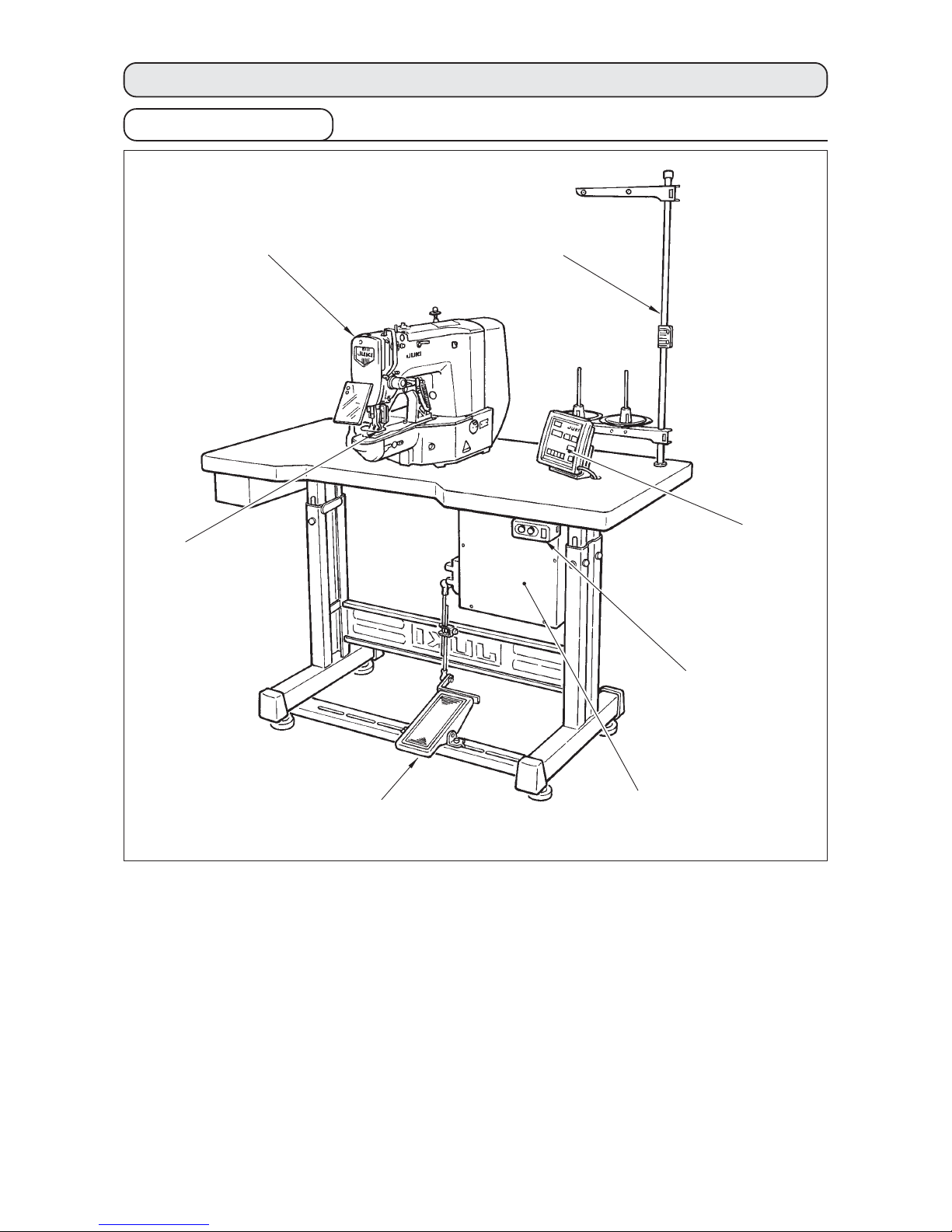
[2] CONFIGURATION .................................................................................................................................. 2
1. Names of main unit .......................................................................................................................................... 2
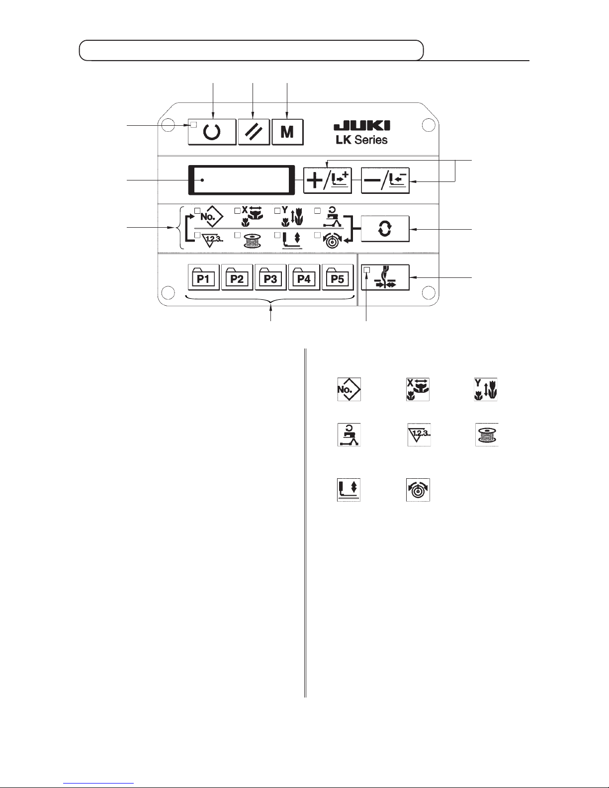
2. Names and explanation of switches on the operation panel ....................................................................... 3
[3] INSTALLATION ...................................................................................................................................... 4
1. Installing the electrical box ............................................................................................................................. 4
2. Attaching the connecting rod ......................................................................................................................... 4
3. Installing the head support rod ...................................................................................................................... 4
4. Installing and connecting the power switch.................................................................................................. 5
5. Installation of the sewing machine head ....................................................................................................... 6
6. Installing the drain receiver and the head support rubber .......................................................................... 6
7. Safety switch .................................................................................................................................................... 7
8. Tilting the sewing machine head .................................................................................................................... 7
9. Installing the operation panel ......................................................................................................................... 8
10. Connecting the cord ........................................................................................................................................ 9
11. Installing the motor cover ............................................................................................................................. 10
12. Managing the cord ......................................................................................................................................... 11
13. Installing the eye protection cover ............................................................................................................... 11
14. Installing the thread stand ............................................................................................................................ 12
[4] OPERATION OF THE SEWING MACHINE .......................................................................................... 13
1. Lubrication ..................................................................................................................................................... 13
2. Attaching the needle ...................................................................................................................................... 13
3. Threading the machine head ........................................................................................................................ 14
4. Installing and removing the bobbin case .................................................................................................... 14
5. Installing the bobbin ...................................................................................................................................... 15
6. Adjusting the thread tension ........................................................................................................................ 15
7. Adjusting the thread take-up spring ............................................................................................................ 16
8. Example of the thread tension ...................................................................................................................... 17
[5] OPERATION OF THE SEWING MACHINE (BASIC) ...........................................................................16
1. Item data setting ............................................................................................................................................ 16
2. Checking the contour of a sewing pattern .................................................................................................. 19
3. Sewing ............................................................................................................................................................ 20
4. Change to the other sewing pattern ............................................................................................................. 20
5. Winding a bobbin ........................................................................................................................................... 21
6. Thread clamp device ..................................................................................................................................... 22
[6] OPERATION OF THE SEWING MACHINE (ADVANCED) ..................................................................24
1. Performing sewing using the pattern keys ( , , , and ) ....................................................... 24
2. Performing sewing using the combination function .................................................................................. 27
3. Performing sewing using the “bobbin thread counter” ............................................................................. 29
4. How to use the temporary stop .................................................................................................................... 29
5. Setting the pattern thread tension ............................................................................................................... 30
6. Cautions in operation .................................................................................................................................... 31
[7] MAINTENANCE ................................................................................................................................... 31
1. Adjusting the height of the needle bar ........................................................................................................ 31
2. Adjusting the needle-to-shuttle relation ...................................................................................................... 32
3. Adjusting the lift of the work clamp foot ..................................................................................................... 33
4. The moving knife and counter knife............................................................................................................. 33
5. Needle thread clamp device .......................................................................................................................... 34
6. Adjustment of the wiper ................................................................................................................................ 34
7. Draining waste oil .......................................................................................................................................... 35
8. Amount of oil supplied to the hook .............................................................................................................. 35
9. Replacing the fuse ......................................................................................................................................... 35
10. Changing the voltage of 100/200V ................................................................................................................ 36
11. Replenishing the designated places with grease ....................................................................................... 37
[8] HOW TO USE THE MEMORY SWITCH ............................................................................................... 38
1. Start and change of the memory switch ...................................................................................................... 38
2. Example of the memory switch setting ....................................................................................................... 38
3. Table of functions of the memory switch .................................................................................................... 42

iv
[9] OTHERS ............................................................................................................................................... 45
1. Setting the DIP switch ................................................................................................................................... 45
2. Table of the standard pattern specifications ............................................................................................... 46
3. Table of the standard patterns ...................................................................................................................... 47
4. Table of the work clamp foot ......................................................................................................................... 49
5. LK-1900 data ROM ......................................................................................................................................... 51
6. Connection of the optional pedal ................................................................................................................. 51
7. Error list .......................................................................................................................................................... 52
8. Troubles and corrective measures (sewing conditions) ............................................................................ 55
9. Table of the optional parts ............................................................................................................................ 57
2.EXPLANATION OF THE LK-1901A, COMPUTER-CONTROLLED HIGH-SPEED
EYELET BUTTONHOLE BARTACKING MACHINE ................................................. 59
1. Specifications ................................................................................................................................................. 59
2. Installation of the sewing machine and preparation of the operation ...................................................... 59
3. Adjustment of the material closing amount ................................................................................................ 60
4. Adjustment of the lift of the work clamp foot .............................................................................................. 60
5. Adjustment of the pressure of the work clamp unit ................................................................................... 61
6. Setting of the material closing operation .................................................................................................... 61
7. Selection and confirmation of the sewing patterns .................................................................................... 62
3.EXPLANATION OF THE LK-1902A, COMPUTER-CONTROLLED HIGH-SPEED
BELT-LOOP ATTACHING MACHINE ........................................................................ 63
1. Specifications ................................................................................................................................................. 63
2. Installation of the sewing machine and preparation of the operation ...................................................... 63
3. Threading the machine .................................................................................................................................. 63
4. Selection and confirmation of the sewing patterns .................................................................................... 64
5. Combination of the work clamp foot and the feed plate ............................................................................ 64
4.EXPLANATION OF THE LK-1903A, COMPUTER-CONTROLLED
HIGH-SPEED LOCKSTITCH BUTTON SEWING MACHINE ................................... 65
1. Specifications ................................................................................................................................................. 65
2. Installation of the sewing machine and preparation of the operation ...................................................... 65
3. Needle and thread .......................................................................................................................................... 65
4. Various sewing modes .................................................................................................................................. 66
5. Position of the button clamp jaw lever ......................................................................................................... 67
6. Adjusting the feed plate ................................................................................................................................ 68
7. Adjusting the button clamp jaw lever .......................................................................................................... 68
8. Adjusting the lifting amount of the button clamp ....................................................................................... 69
9. Adjustment of the pressure of the work clamp unit ................................................................................... 69
10. Adjustment of the wiper spring .................................................................................................................... 70
11. Installing the save button bar (accessory part) .......................................................................................... 70
12. Model classification according to the button size ...................................................................................... 71
13. Attaching the shank botton (optional) ......................................................................................................... 72
5.DRAWING OF THE TABLE ...................................................................................... 76

−1 −
1.EXPLANATION OF LK-1900A, COMPUTER-CONTROLLED HIGH-
SPEED BARTACKING MACHINE
[1] SPECIFICATIONS
1) Sewing area ................................................. X (lateral) direction 40 mm Y (longitudinal) direction 30 mm
2) Max. sewing speed ...................................... * 3,000 rpm
(When sewing pitches are less than 5 mm in X-direction
and 3.5 mm in Y -direction.)
3) Stitch length ................................................. 0.1 to 10.0 mm (adjustable in 0.1 mm step)
4) Feed motion of work clamp foot ................... Intermittent feed (2-shaft drive by stepping motor)
5) Needle bar stroke ........................................ 41.2 mm
6) Needle.......................................................... DP x 5, DPx17
7) Lift of work clamp foot .................................. 13 mm (standard) Max. 17 mm
8) Shuttle .......................................................... Standard semi-rotary hook (oil wick lubrication)
9) Lubricating oil ............................................... New Defrix Oil No. 2 (supplied by oiler)
10) Data recording ............................................. EE-PROM (128Kbyte) E-PROM (32kbyte)
11) Enlarging / Reducing facility ........................ 20% to 200% (1% step) in X direction and Y direction
respectively
12) Enlarging / Reducing method ...................... Pattern enlargement / reduction can be done by increasing/
decreasing the stitch length
13) Max. sewing speed limitation ....................... 400 to * 3,000 rpm (100 rpm steps)
14) Pattern selection .......................................... Specifying pattern No. type (1 to 200)
15) Bobbin thread counter ................................. UP/DOWN type (0 to 9999)
16) Sewing machine motor ................................ 450W servo motor
17) Dimensions .................................................. W : 1,200 mm L : 660 mm H : 1,100 mm
(Use the standard table and stand.)
18) Weight .......................................................... Machine head 42 kg, Control box 16.5 kg
19) Power consumption ..................................... 320 W
20) Operating temperature range ...................... 5 ˚C to 35 ˚C
21) Operating humidity range ............................ 35% to 85% (No dew condensation)
22) Line voltage ................................................. Rated voltage ±10% 50/60 HZ
23) Noise ............................................................ Workplace-related noise at sewing speed
n = 3,000 min–1 : LPA ≦84 dB(A)
Noise measurement according to DIN 45635-48-A-1.
* Reduce the max. sewing speed in accordance with the sewing conditions.

−2 −
[2] CONFIGURATION
1. Names of main unit
qMachine head
wWork clamp feet
eThread stand
rOperation panel
tPower switch
yControl box
uPedal switch
q
w
e
r
t
y
u

−3 −
2. Names and explanation of switches on the operation panel
q“Ready” key
This key changes over the setting state from the
panel to the sewing state where the sewing
machine actually operates.
wSewing LED
This LED goes off at the time of setting state and
lights up at the time of sewing state. Changeover
can be performed with “Ready” key.
e“Reset” key
This key is used for canceling error or returning
the set value to the initial value.
r“Mode” key
This key makes the setting mode of the memory
switch.
t“+/Feed forward” key and “-/Feed backward” key
This key is used for changing pattern No. and X/Y
scale, and feed forward/feed backward.
y“Selection” key
This key selects the item to be set. Item selection
LED of the selected item and the set value are
displayed.
uData indication LED
This LED indicates the set values of the selected
items such as pattern No., X/Y scale, etc.
iItem selection LED
LEDs of the selected items light up.
oNeedle thread clamp ON/OFF key
This key selects effective/ineffective of needle
thread clamp. When it is effective, needle thread
clamp display LED lights up. (Note 1)
!0 Needle thread clamp display LED
When this LED lights up, needle thread clamp
operates.
!1 Needle thread clamp display LED
This key registers the pattern. When this key is
pressed, the pattern registered here can sew
immediately.
X/Y scale, sewing position, etc. can be changed
and registered.
Pattern No. X scale Y scale
Max. speed
limitation
Sewing
counter
Bobbin
winder
Work clamp
foot lowering
Thread
tension
q
w
t
re
y
u
i
o
!0!1
(Note 1) LK-1903A is set to needle thread clamp prohibited (no motion) with memory switch No. 35 at
the time of standard delivery.

−4 −
[3] INSTALLATION
1. Installing the electrical box
Install the electrical box on the underside of the table
at the location illustrated using round-head bolt q, plain
washer w, spring washer eand nut rsupplied with
the machine, and using bolt having hexagonal
indentation on the head t, spring washer yand plain
washer usupplied with the machine.
q
w
t
r
e
y
u
q
w
e
A
B
2. Attaching the connecting rod
1) Fix connecting rod qto installing hole Bof pedal
lever wwith nut e.
2) when connecting rod qis installed in installing hole
A, the depressing stroke of the pedal is increased.
3. Installing the head support rod
Drive head support rod qin hole win the machine
table.
q
w

−5 −
4. Installing and connecting the power switch
(1) Installing the power switch
Fix power switch 笊under the machine table with wood
screws 笆.
Fix the cable with staples 笳supplied with the machine
as accessories in accordance with the forms of use.
*Five staples 笳including the staple for fixing the
operation panel cable are supplied as accessories.
(2) Connecting the power source cord
Voltage specifications at the time of delivery from the factry are indicated on the voltage indication seal.
Connect the cord in accordance with the specifications.
1. Never use under the wrong voltage
and phase.
2. When changing the voltage, refer to
the item of "Changing the voltage
of 100 / 200V" (P.36).
Voltage indication seal (3-phase type only)
Voltage caution seal
Rating label
Table
Brown Brown
Brown
Light blue Light blue
Light
blue
Green/Yellow Green/
Yellow
Control box
Green/Yellow
Plug
Power source cord
Power switch
GND
AC200 V
AC220 V
AC230 V
AC240 V
• Connecting single phase 200V, 220V, 230V and 240V
Table
Red
Black
Green/Yellow
White
Control box
Power source cord
Plug
Power switch
GND
AC200 V
AC220 V
AC240 V
• Connecting three phase 200V, 220V and 240V
Green/Yellow
Red
White
Black
Green/
Yellow
Red
Black
White
笊
笆
笳

−6 −
1) Fit hinge rubber qto the hinge shaft ,and fix the
sewing machine main unit.
2) When tightening nut eto hinge rubber q, tighten
nut euntil spring washer wbecomes as B in the
illustration, and fix it with nut r.
If tightening hinge rubber qexcessively, it
will not work properly. So, be careful.
Hold section Awhen moving the sewing
machine.
5. Installation of the sewing machine head
A
Aq
q
WARNING :
To prevent possible accidents caused by the full of the sewing machine, perform the work by two persons
or more when the machine is moved.
1) Fix drain receiver win the installing hole of table
qwith four setscrews e.
2) Screw in drain bin rto drain receiver w.
3) Insert sewing machine drain pipe tinto drain bin
r.
4) Insert head support rubber yinto table q.
1. Insert drain pipe tuntil it will go no
further so that it does not come off
drain bin rwhen tilting the machine
head.
2. Remove the tape fixing drain pipe t.
q
w
t
r
e
6. Installing the drain receiver and the head support rubber
w
e
r
w
er
w
e
r
w
w
y
y
A
B

−7 −
When tilting the sewing machine head, tilt the head
gently until it comes in contact with head support rod
q.
1. Before tilting the sewing machine head,
make sure that head support rod qis
attached to the machine table.
2. When raising the sewing machine
head, do not raise it while holding
motor cover w. It will be the cause of
breakage of motor cover w.
3. Be sure to tilt the sewing machine head
on a flat place to prevent it from falling.
8. Tilting the sewing machine head
q
w
WARNING :
Tilt/raise the sewing machine head with both hands taking care not to allow your fingers to be caught in
the head. Turn OFF the power before starting the work so as to prevent accidents caused by abrupt start
of the sewing machine.
7. Safety switch
q
w
Impor tant
w
Remove tape qfixing the lever section of safety switch w.
1. When using the safety switch without removing tape q, it is very dangerous since the
sewing machine works even in the state that it is tillted.
2. In case error 302 occurs when the sewing machine works after setup, loosen the safety
switch fitting screw with a screwdriver, and lower the switchto the downside of the sewing
machine.

−8 −
9. Installing the operation panel
Fix operation panel installing plate qon the machine
table with wood screws wand pass the cable through
hole rin the machine table.
Fix the operation panel on panel installing plate qwith
screws esupplied as accessories.
Fix the cable on the bottom surface of the table with
the staples supplied with the machine as accessories.
Refer to the figure on the left side when installing the
panel under the table.
q
w
r
e
q
e
w

−9 −
CN38 Gray
10. Connecting the cord
Remove four screws E fixing the rear cover of the
electrical box. When opening the rear cover, pressing
it with your hands, slowly open it by approximately 90˚
until it stops as illustrated.
Be sure to lend your hand to the rear cover
in order not to let the rear cover fall. In
addition, do not apply force to the rear
cover opened.
q
CN16
CN14
CN39
CN42
CN43
CN44
CN45
CN40
CN47
CN38
CN34
4P
9P
2P
6P
6P
6P
6P
4P
2P
16P
26P
White
Yellow
White
Blue
Red
Yellow
White
White
Gray
Gray
(LK-1901A)
Sewing machine head
Operation panel
CN14 White
CN16 White
Earth cord
CN34 Gray
CN45
Yellow
CN47
White
CN42 White
CN43 Blue
CN39 Yellow
CN44 Red
CN40
White
Slowly
White

−10 −
1) Take care so that the cord is not caught between
the rear cover and the electrical box main body,
close the rear cover while pressing section A on
the lower side of the rear cover, and tighten four
screws q.
2) Lower downward the cord located on the side of
the control box and cord presser plate C in the push
hole B, press the cord and tighten screws w.
e
qLightly press the corner of clamp.
(Cord clamp is locked with a click.)
How to lock the cord clamp
q
w
q
q
w
A
B
C
11. Installing the motor cover
Install motor cover qon the machine main unit with
screws supplied with the machine as accessories.
q
q
q
w
Clamp
How to remove the cord clamp
qLightly pressing
wPull down the clamp.
eThe clamp goes up.

−11 −
12. Managing the cord
q
w
Slack
Be sure to install and use eye protection cover q.
13. Installing the eye protection cover
q
1) In the state that the sewing machine is tilted, connect the cords, and bundle them with clip band qas
shown in the figure.
2) Fix the cords with cords setting plate win the state that the cords slacken as shown in the figure.
When you tilt the sewing machine, make sure that the sewing machine head support bar is
placed on the table.
WARNING :
Be sure to attach this cover to protect the eyes from the disperse of needle breakage.

−12 −
14. Installing the thread stand
1) Assemble the thread stand unit, and insert it in the
hole in the machine table.
2) Tighten locknut qto fix the thread stand.
3) For ceiling wiring, pass the power cord through
spool rest rod w.
q
w

−13 −
Loosen setscrew qand hold needle wwith the long
groove facing toward you. Then fully insert it into the
hole in the needle bar, and tighten setscrew q.
If the stitches are made as shown in A,
attach the needle facing to the direction
Bto a small extent.
[4] OPERATION OF THE SEWING MACHINE
1. Lubrication
2. Attaching the needle
w
e
A
B
WARNING :
Turn OFF the power before starting the work so as to prevent accidents caused by abrupt start of the
sewing machine.
WARNING :
Turn OFF the power before starting the work so as to prevent accidents caused by abrupt start of the
sewing machine.
q
Check that the place between lower line B and upper
line A is filled with oil. Fill there with oil using the oiler
supplied with the machine as accessories when oil is
short.
*The oil tank which is filled with oil is only for
lubricating to the hook portion. It is possible to
reduce the oil amount when the number of rotation
used is low and the oil amount in the hook portion
is excessive. (Refer to 8. Adjusting the amount of
oil in the hook of [7] MAINTENANCE.)
1. Do not lubricate to the places other
than the oil tank and the hook of
Caution 2 below. Trouble of
components will be caused.
2. When using the sewing machine for the
first time or after an extended period
of disuse, use the machine after
lubricating a small amount of oil to the
hook portion. (Refer to 2. Needle and
hook of [7] MAINTENANCE.)
A
B

−14 −
1) Open hook cover q.
2) Raise latch eof bobbin case w, and remove the
bobbin case.
3) When installing the bobbin case, fully insert it into
the shuttle shaft, and close the latch.
If it is not fully inserted, bobbin case w
may slip off during sewing.
3. Threading the machine head
Pull out the thread by approximately 4 cm from the needle after threading through the needle.
1. When the silicon oil is used, thread through thread guide for silicon q(Optional)
2. For thick thread, pass the thread through one hole only of needle bar thread guide w.
4. Installing and removing the bobbin case
q
w
e
WARNING :
Turn OFF the power before starting the work so as to prevent accidents caused by abrupt start of the
sewing machine.
WARNING :
Turn OFF the power before starting the work so as to prevent accidents caused by abrupt start of the
sewing machine.
q
w
Thin synthetic thread or the like
Other manuals for LK-1900A
1
This manual suits for next models
4
Table of contents
Other JUKI Sewing Machine manuals

JUKI
JUKI MB-372 User manual

JUKI
JUKI MB-1800 series User manual

JUKI
JUKI SC-921 User manual

JUKI
JUKI LU-2210N-7 User manual

JUKI
JUKI DDL 552 User manual

JUKI
JUKI LZ-2280N Series Owner's manual

JUKI
JUKI MF-7200D User manual

JUKI
JUKI DSC-246 User manual

JUKI
JUKI SC-920 Quick start guide

JUKI
JUKI JTR-DDL9000B/PPA User manual

JUKI
JUKI LK-1901A User manual

JUKI
JUKI K-1E User manual

JUKI
JUKI TL-2200QVP Mini User manual

JUKI
JUKI MO-634DEV User manual

JUKI
JUKI LBH-1790S User manual

JUKI
JUKI MF-7700D Series User manual

JUKI
JUKI LZ-2290A Series User manual

JUKI
JUKI DDL-8700 User manual

JUKI
JUKI DDL-9000C-F Series User manual

JUKI
JUKI AC-172N-1790AN User guide