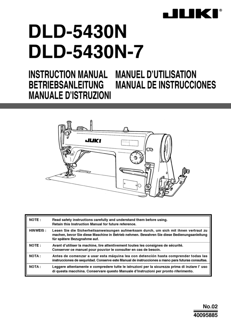
JUKI DLN-415 User manual


DLN-415 SPECIFICATIONS
Sewing
speed
.._...__.___._
Up to 5,000
s.p.m.
Stitch length . .
.._._______._.
O-4mm(5/32”)
Stitch adjuster
.._._._._._..._
Dial system
Reverse sewing
.._._...._._
Lever system
Needles
.._.__._.___._.__....
DB Xl (16x231)
#ll,
#14, #16, #la
Lubricating oil
.._.___.__.
New Defrix Oil No. 1

DLN-415 CONTENTS
Adjusting
the
pressure of the
pre5w foot ..............................................................................
8
The PrePser
foot
hand
liffer ......................................................................................................
8
Height of
the
feed dog
...............................................................................................................
8
The
stitch
length
........................................................................................................................
9
Adjusting the stitch
length
.........................................................................................................
9
Reverse sewing
...........................................................................................................................
9
Purhing
weswre
Of
the
‘eed lever
.............................................................................................
9
inserting
the neel3e
.....................................................................................................................
10
l”$talling
and
removing
rhe sewing
hook .................................................................................
10
Relation txiween
the hOOk
and
the needle
...........................................................................
1,
Adjusting
the height of the presser bar
....................................................................................
12
Adjusting the amount
of
tiw thread takeup ...........................................................................
12
DLN-415L INSTRVCTlCN BOOK .......................................................................................
13
,NOWl
Due
fO
impro”ementr
0”
the
machine.
some
Dam
Of
rtle
operational
procedures
of
this
lNSiRUCTlON
BOOK
might
be
changed
wittlaut
notice.

IINSTALLING THE OIL RESERVOIR
Operator side Hinge side
MOTOR PULLEY AND THE BELT
As
shown in the figure.
set
the reservoir in
such
a way
50
that
the 4
corners
01
the grow-
ed part of the table will be supporting the
reservoir.
1.
Nail in the 2 rubber
cushionr
in front to
the protruding part
01
the table.
2.
place
the oil
reservoir
on the protruding
part of the table.
,b,ade,
~Lt4-4,5
can
sew
at a high speed oi
up
to
5.000
r.p.m.
When connected directly
to
the
power
source.
use
a 3-phase 400 W
(l/2
HP) clutch mata.
Use a
hl
type V-belt. The relation between
the number
oi
rotation oi the machine with
the
dimenrion of the motor pulley is shown in
the table. (Effective diameter)
*
The effective diameter
oi
the motor pulley
rnGk”S
the diameter
a~
measured from the
center of the V-belt when the belt is wound
around the machine.
Cycle
50
60
No. of rotation
of machine
5.060
5.p.m.
4,630
5.p.m.
5,040
5.p.m.
4,540
5.p.m
Part
KO.
of
mOtol
pulley
MTK-P”120000
MTK-P0110000
MTK-P”,O”OOC
hlTK-P”090000
Effective diameter
of
motor
pulley
120mm
(4-9/W)
IlOmm (43/16”)
~lOOnlrn
(3.3/16”)
90mm
(3-T/16”)
-2-

CAUTIONS ON OPERATING THE MACHINE
.?
Do not run the machine. under
anv
circumrtances, before the oil
reservoir
is
filled up
with fresh oil.
is
This machine can run with a
meed
of
“11
to 5.000
r.o.m.
but for the iirst month drop
the speed
to
about 4,500
r.p.m.
LUBRICATION
Before operating the machine
1. Fill up
Ihe
oil reservoir with IUK
New
~eirix
oil
~0.3
up
to
the mark “HIGH”.
2. Watch and see that the oil level doer not
go
below the “LOW” mark.
3. Under
normal
conditions, when the ma-
chine
is
run after
il
is filled up with oil, the
oil will spurt against the oil right window
(Caution)
1) When the oil
gets
dirty, change it with’new.
fresh oil. If the
oil
plug
oi
the
veservob
is
removed, oil will come
out.
2) When the
mathine
is to be run for the first
time
or
when it
wan
idle for a great length
of time, run the machine at 3,000- 3,500
s.p.m.
for about
10
minutes and allow the
machine to
get
well-oiled.
-3-

1. Adjusting the oil supply to the face
Pad
When xliusting the oil supply to the thread
take-up and needle bar crank components,
remove the Iaw plate and the oil prevrnt-
ing plate and adjust by turning the oil ad-
justing pin at the tip of the main shaft.
1.
When the
red
mark of the adjusting pin
comer near the crank. the oil amount gets
le5s.
2. When the red mark comes to the opposite
side
of
the crank, the oil amount gets more.
(Caution)
The oil amount doer not
thongs
immedi-
ately after the odiurtment, so when ad-
1
jurting, hove this
ii
mind.
2. The oil adjusting pin
‘I. The oil adjusting pin has a carved groove
as
shown in the figure. When this groove
and the oii hole oi the main rhait come
rogcthpr, the oil amount gets more.
2. When the groove
is
at the opposite side of
the oil hole, the oil amount
gets
Ierr.
3. The red mark on the oil adjuster shows the
ride without the carved groove.
3. Adjusting the oil supply to the hook
components
The supply of oil to the hook components
cm be adjusted by the oil regulating valve an
the hook shaft.
1.
If
this valve is turned toward
0
ride(right),
the oil amount gets more.
2. If this valve is turned to
0
side (left), the
amOunt geri
les

THREADING THE MACHINE
Rotate the hand wheel mright and place the thread take-up to the highest positiart.
1.
Pass
the needle thread in the order shown by the iigure.
2. Pair ihe thread to the needle eye lrom
lcit
to righr.
3. Pull out about
70cm(4”)
of the thread from the needle eye.

PREPARATION OF THE BOBBIN THREAD
How to insert the bobbin
1.
Hold the bobbin and inert it to the bobbin
case
50
that
Lhe
thread \vill be in right-hvist
condilion.
2. Pair the thread to the thread pasring hole
oi the bobbin case.
-6

THE THREAD TENSION
,
Adjusting the needle thread tension
Ideal stitches
are
iormcd
wlwn
the
needle
thread and the bobbin thread are
perfectly
interlocked at the center
ot
the cloth.
The tension of the needle thread is adjusted
by the thread tension nut.
1. Turn it to right
to
make the tension stronger
and to the leit to make it we&r.
Thread take-up spring
* To change the moving range oi the thread
tenson spring:
1. Loosen the screw al
the
thread tension
bracket.
2. Rotate the thread tension bar.
* To
change
the strength oi the thread
take-
up
spring
1. Loosen the ret screw, remove the thread
tenrion bar
2. Loosen the thread tension bar set
screw
and adjust.
3. When the thread tension bar
is
turned
to
right, the spring will get stronger and ii
turned to
left,
it
Gil
xet
weaker.
Adjusting the bobbin thread tension
Rotate the thread tension screw ai lhe
bobbin case to adjust the bobbin thread
tensian.
1.
Rotate if
to
right
to
make the bobbin thread
tension stronger and to left to make it
weaker.
-7-

PRESSER FOOT AND FED9
DOG
5 kg
(ll’lbr). -
if a pressure of
mare
than
6
kg(13.2
Ibs)
is
required, use the exchanging rpring in the
atcersory box
The presser foot hand lifter
To stop the prerser foot at the lifted po-
sition:
1.
Rotate
the hand liiter in the
war
of the face
part either to right or left.
2. The presser foot will go up about 5 mm
(13/64”) and rtopi.
3.
ia
lower the presser foot, activate the knee
lifter
once
and the presw foot will cmne
down
to
the original position.
4. With the knee liiter, the prerrer foot
nilI
go up about
Wmm(25/64”)
Height of the feed dog
The height a, the feed dog from the surface
of the throat plate is set from 0.7.0.8mm. In
sewing
light weight materiali, if this height is
too
high, shrink-stitching may
result.
To
adjust the height of the feed dog:
7.
Looseri the clamping
scre~v
of the
teed
driv-
ing fork of the compound feed.
2.
>M~ave
the feed dog base up and dawn and
.tdjust.
3. After adjusting, tightly tighten the clamping
5crew.
cl.?-o.*mm

THE STITCH LENGTH
L
Adjusting the stitch length
The stitch length can be
adjurteo
sly
rumng
the
iced
adjusting
dial
above the feed
lever.
The
iigurei
an
the
graduator are rhown in
mm.
2.
And
match
the desired
figure
with the pin
which
ii
coming au! irorn the arm.
* The
maximum
stitch length is
4mm
(5/32”)
Pushing pressure of the feed lever
Irrespective
oi
the length of stitches, the
pull-up
spring
is somewhat strengthened
IO
that during high speed sewing if the hand
is
releawd
lrom
the feed
lever.
it will positively
return to the original position.
When
shorter
stitcher
are
desired
or
when
the
rotation
of the machine
is
to be slowed
down, it
ii
pasrible
to
decrease the pushing
preriure oi
the
feed lever.
1.
When the adjurting nut ii loosened, the
pressure will become weaker and ii the nut
is
tightened, the pwssure will became
stronger.
-9-

INSERTING THE NEEDLE
INSTALLING AND REMOVING
r
“re
DB
X
1
needler. There are many
numbers and
sizes
of the needle,
IO
select
the mrrect size and number depending
on
the
thickness of the thread
or
kinds of sewing
material.
1. Rotate the hand wheel and bring the needle
bar to the highest porition.
2. Loosen the needle clam,, screw.
3. Hold the needle so that the long groove
of
the needle comes to your
leit
side.
4. insert the needle deep into the needle hole
5. Then securely tighten the needle clamping
screw.
THE SEWING HOOK
-
10
-
During the running of the machine, if thread
hardr
get into
rhe
hook or the position
ai
the
hook changes for
borne
reason
01
to exchange
the hook with a new one, do
ar
follows in
order:
1.
Rotate
the hand wheel and bring the needle
bar to the highest position.
2.
Remove the bobbin
case
and the needle
3. Remove the bobbin
case
base positioning
finger
ret screw and take out the bobbin
case
positioning finger.
4.
Loaren
the 3 xrews of the sewing hook.
5. Rotate the hand wheel and raise up the
feed base
to
its
highest position.
6. Rotate the sewing hook with your hand
and
place
it in the
position
ar
shown in
the figure.
7. Pull the hook to your left and take it
out.
*
To install the hook back, reverre this pro-
cedure.

RELATION BETWEEN THE HOOK AND THE NEEDLE
Match
the
needle with the sewing hook
as
tallows:
1.
Rotate the hand
wheel
and bring the needle
bar to its lowest position.
2. Loosen the needle bar clamping
set
screw.
(Note)
When matching the timing of the needle and
the sewing hook, be sure to ret the feed
adjusting dial to “0”.
(Determine the height of the needle
bar]
3.
hlatch
the upper
c,,ived
linc
01
the
needle
bar with the lower edge
ai
the needle bar
low, bushing.
4. Tighten the needle bar
clamoing
ret
screw
3
DETER!vlINE THE POSITION
OF THE SEWING HOOK
7. Rotate the hand wheel and match the
lower
carved line of the needle bar with the
lower
edge
of the needle bar lower bushing.
8. In this condition. match the blade point of
the
haok
with the center line of the needle
9. Make the clearance
between
the needle
and the hook blade point to 0.05 mm and
10.
Securely tighten the hook clamping set
screw
(Determine the position of the sewing
hook)
5.
Laaren
the
3 clamping screws of the hook
so that the hook can be rotated freely with
the hand.
6.
Place the hook with your hand to thethread
pass/rig
position

ADJUSTING THE HEIGHT OF THE PRESSER BAR
r
When the height
or
the direction
of
the
presser bar is to be changed due
to
the
exchange of
presrer
foot:
1. Remove the rubber plug of the face plate
2.
From this hole. adjust by loosening the
prerrer bar clamping screw.
3. After the adjustment, securely tighten the
ret
5crew.
;I
ADJUSTING THE AMOUNT OF THREAD TAKE-UP
/.I\\
3-7
b
/
I
/
The
amount
of the thread take-up should
be changed according to the length
oi
stitcher
or
thickness
af
the sewing cloth
to
produce
ideal thread tension.
1. When sewing heavy weight materials,
move
the thread guide
to
your left.
The thread rake-up amount of the take-up
gets more.
2. When sewing light weight materials.
move
the thread guide
to
your right.
The thread take-up amount
gets
less.
-
12
-

INSTRUCTION BOOK
DLN-415-L
SPECIFICATIONS
Sewing speed ..,........._.....,_...,.,., Up to 3,000
s.p.m.
Stitch Icngth .,............,.............. 0
-
6mm(15/64”)
Needle _.......,...,....,_.........,.,....... DB X
1
#22
USAGE
Fur lop stitching of heavy weight materials (up to 12 sheets of Canton material)
(Example) Seats of cars. brief cases, slippers etc.
TIMING OF THE NEEDLE WITH THE SEWING HOOK
When the needle has risen 1.8mml,5/64”), from
its lowest dead point, the distance between the
upper end of the needle
eye
and the blade point
of
the,
scwin~ hook should he ?.8mm(7/64”~.
With the exception of above, all other specifications
xe
identical with DLN-415.
-
13
-
At that point, the clcarancc between the needle
and the biadc point of the sewing hook should
be O.lmm(1/256”). (when the feed amount is
“O”.)
Table of contents
Other JUKI Sewing Machine manuals

JUKI
JUKI DLU-5494N-7 User manual

JUKI
JUKI DDL 552 User manual

JUKI
JUKI LH-3528A User manual

JUKI
JUKI LS-341N User manual

JUKI
JUKI HZL-F series User manual

JUKI
JUKI HZL-E71 User manual

JUKI
JUKI LS-1340 User manual
JUKI
JUKI AMS-210EN/IP-420 User manual

JUKI
JUKI IP-310/ACF-172-1790 User manual

JUKI
JUKI DNU-1541 User manual

JUKI
JUKI MO-735 User manual

JUKI
JUKI HZL-12Z User manual

JUKI
JUKI DP-2100 User manual

JUKI
JUKI DDL-9000BHS User manual

JUKI
JUKI LZ-2284N-7 User manual

JUKI
JUKI DU-1181N User manual

JUKI
JUKI DNU-1541 Quick start guide

JUKI
JUKI UnionSpecial 35800DLU Setup guide

JUKI
JUKI LU-1510N-7 Quick start guide

JUKI
JUKI J-350QVP User manual