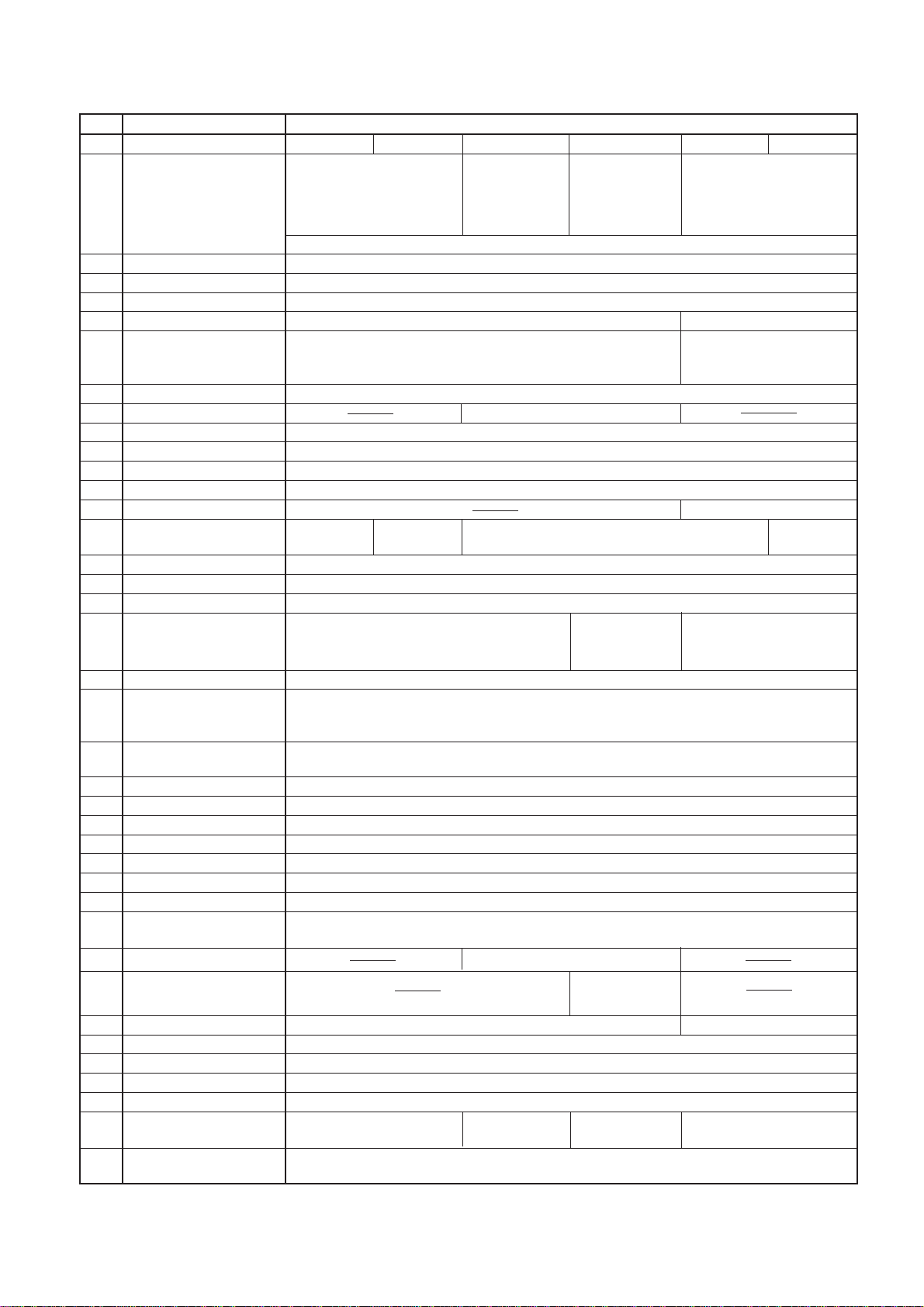
JUKI LU-2210N-7 Quick start guide

29227501
No.E306-04
ENGINEER’S MANUAL
1-NEEDLE, HIGH-SPEED, UNISON-FEED LOCKSTITCH MACHINE WITH VERTICAL-AXIS LARGE HOOK
AND AUTOMATIC THREAD TRIMMER
LU-2210N-7 LU-2210W-7
®
1- NEEDLE, HIGH-SPEED, UNISON-FEED LOCKSTITCH MACHINE WITH VERTICAL-AXIS LARGE HOOK
AND AUTOMATIC THREAD TRIMMER (2P DIAL)
LU-2212N-7
2- NEEDLE, HIGH-SPEED, UNISON-FEED LOCKSTITCH MACHINE WITH VERTICAL-AXIS LARGE HOOK
AND AUTOMATIC THREAD TRIMMER
LU-2260N-7 LU-2260W-7
1- NEEDLE, HIGH-SPEED, UNISON-FEED LOCKSTITCH MACHINE WITH VERTICAL-AXIS LARGE HOOK
AND AUTOMATIC THREAD TRIMMER (NEEDLE THREAD CLAMP DEVICE/2P DIAL)
LU-2220N-7

Introduction
This Engineer’s Manual is for technical service engineers. In the instruction manual for the maintenance engi-
neers of sewing machines and sewing workers in a sewing factory, how to operate a sewing machine is also
described in detail. However, in this manual, [Adjustment Procedure], [Results of Value Change for Adjustment],
and the roles of each component are described: these are not included in the instruction manual.
When maintenance is performed for our sewing machines, refer not only to this manual, but also to the instruction
manual and parts list.
This engineer’s manual describes the basic adjusting values as the reference values in the first page, and the
observed events caused by sewing and mechanical faults as the [Results of Value Change for Adjustment] and
[Adjustment Procedure] in the second page.

CONTENTS
1. Specifications ......................................................................................................... 1
2. Model Numbering System ...................................................................................... 2
(1) LU-2210N/W-7 ............................................................................................................................ 2
(2) LU-2212N-7 ................................................................................................................................ 3
(3) LU-2260N/W-7............................................................................................................................ 4
(4) LU-2220N-7 ................................................................................................................................ 5
3. Standard Adjustment.............................................................................................. 6
(1) Types and Names of Gradations on the Hand-wheel ............................................................ 6
(2) Sewing Speed............................................................................................................................ 7
(3) Needle Entry .............................................................................................................................. 8
1) Needle entry in the needle slot of the feed dog in the lateral direction ............................................................ 8
2) Needle entry in the needle slot of the feed dog in feeding direction
(LU-2210N/W-7, 2260N/W-7, 2212N-7) ................................................................................................................ 10
3) Needle entry in the needle slot of the feed dog in feeding direction (LU-2220N-7)....................................... 12
(4) Needle-to-Hook Relation ........................................................................................................ 14
1) Height of the Needle Bar...................................................................................................................................... 14
2) Clearance between the Needle and the Blade Point of Hook........................................................................... 16
3) Timing between the Needle and the Hook ......................................................................................................... 18
(5) Clearance between the Throat Plate and the Inner Hook Stopper ..................................... 20
(6) Timing of the Cloth Feed Action............................................................................................ 22
1) Horizontal Feed Timing........................................................................................................................................ 22
2) Vertical Feed Timing ............................................................................................................................................ 22
3) Upper Feed Timing............................................................................................................................................... 24
4) Height of the Feed Dog ........................................................................................................................................ 26
5) Amount of alternating vertical movement of the walking foot and presser foot
(Balance between the lifting amounts of the presser foot and walking foot) ............................................... 28
(7) Adjustment of the Feed Mechanism...................................................................................... 30
1) Zeroing of the feed adjusting mechanism ......................................................................................................... 30
2) Stitch length in the normal feed and reverse feed ............................................................................................ 32
3) 2P Adjustment (for LU-2212N-7 and LU-2220N-7) ............................................................................................. 34
(8) Position of the Reverse Feed Connecting Arm/the amount of condensation................... 36
(9) Bobbin Winder......................................................................................................................... 38
1) Bobbin Winder Friction Wheel Adjustment ....................................................................................................... 39
2) Bobbin Winding Amount Adjustment................................................................................................................. 39
(10) Thread Trimmer Device (for LU-2210N/W-7 and LU-2260N/W-7) ...................................... 40
1) Counter Knife........................................................................................................................................................ 40
2) Clamp Spring ........................................................................................................................................................ 40
3) Knife Pressure ...................................................................................................................................................... 40
4) Moving Knife Driving Arms A, B and C .............................................................................................................. 40
(11) Thread Trimmer Device (for LU-2212N-7) ........................................................................... 42
1) Positions of Counter Knife and Clamp Spring .................................................................................................. 42
2) Counter Knife Base Position............................................................................................................................... 42
3) Knife Pressure ...................................................................................................................................................... 42
4) Moving Knife Driving Arms A, B and C .............................................................................................................. 42
5) Height of the Moving Knife (for the right-hand side hook) (for LU-2210N/W-7,
LU-2212N-7 and LU-2260N/W-7) .......................................................................................................................... 44

6) Height of the Moving Knife (for the left-hand side hook) (for LU-2260N/W-7)................................................ 46
7) Thread Trimmer Cam (for LU-2210N/W-7 and LU-2260N/W-7) ......................................................................... 48
8) Thread Trimmer Cam (for LU-2212N-7) .............................................................................................................. 50
(12) Thread Trimmer Device (LU-2220N-7) ................................................................................. 52
1) Positioning for the thread trimming cylinder joint ......................................................................................... 52
2) Counter knife (adjustment of movement) (positioning for the counter knife base stopper....................... 54
3) Counter knife (adjustment of right and left positioning) ............................................................................... 56
4) Moving knife (adjustment of vertical positioning).......................................................................................... 58
5) Counter knife (adjustment of vertical positioning)......................................................................................... 58
6) Thread guide mounting position...................................................................................................................... 60
7) Adjustment of knife presser ............................................................................................................................. 60
8) Moving knife driving arm and initial position of the moving knife ............................................................... 62
9) Adjustment of gap between the moving knife driving arm and the moving
knife driving arm stopper.................................................................................................................................. 64
10) Mounting position of the moving knife return plate....................................................................................... 64
11) Adjustment of timing for the thread trimming cam ........................................................................................ 64
12) Clamp spring mounting position ..................................................................................................................... 66
13) Explanation of the solenoid valve.................................................................................................................... 68
(13) Opener.................................................................................................................................... 70
1) Timing of the Opener ........................................................................................................................................... 70
2) Clearance between the opener and the protruding section of the inner hook............................................... 70
(14) Presser Lifting Unit ............................................................................................................... 72
1) Presser Lifting Amount........................................................................................................................................ 72
2) Presser Lifting Cylinder....................................................................................................................................... 72
(15) Safety Mechanism................................................................................................................. 74
1) Releasing Torque Adjustment............................................................................................................................. 74
2) How to reset the Safety Mechanism ................................................................................................................... 74
(16) Lubricating Unit..................................................................................................................... 76
1) Oil Distribution Diagram ...................................................................................................................................... 76
2) Supplying and Replacing Oil............................................................................................................................... 76
3) Filter Replacement Procedure ............................................................................................................................ 78
4) Adjusting the amount of oil in the hook and cleaning the hook filter ............................................................. 78
(17) Aperture Plate Removal Procedure (for LU-2212N-7)........................................................ 80
1) Removal Procedure of Aperture Plate ............................................................................................................... 80
2) Attachment Procedure of Aperture Plate ........................................................................................................... 80
3) Adjustment of 2P Cylinder Connecting Link ..................................................................................................... 80
(18) Aperture Plate Removal Procedure (for LU-2220N-7) ........................................................ 82
1) Removal Procedure of Aperture Plate ............................................................................................................... 82
2) Attachment Procedure of Aperture Plate ........................................................................................................... 82
3) Adjustment of 2P Cylinder Connecting Link ..................................................................................................... 82
4. Various Switches................................................................................................... 84
(1) Operation Switches................................................................................................................. 84
(2) Knee Switch............................................................................................................................. 84
5. Parts Replacement................................................................................................ 86
(1) How to replace the Needle Clamp (LU-2260N/W-7).............................................................. 86
(2) Replacement of the Presser Adjusting Spring ..................................................................... 88
(3) How to replace the Timing Belt..............................................................................................90
(4) How to change from 1-needle to 2-needle specifications (LU-2210N-7 →→
→→
→LU-2260N-7) ...... 96

6. Bed Height Adjustment......................................................................................... 99
7. Parts to be carefully tightened........................................................................... 100
8. Parts to be fixed with LOCK-TITE Paint ............................................................ 101
9. Maintenance Parts List ....................................................................................... 102
10. Mechanism Adjusting Procedure Chart at a Glance...................................... 103
11. Troubles in Sewing and Corrective Measures................................................ 105
(1) Related to Sewing ................................................................................................................. 105
(2) Related to Thread Trimmer....................................................................................................111
12. Replaceable Gauge Table................................................................................. 114
(1) For LU-2210N/W-7, LU-2212N-7 and LU-2220N-7 ............................................................... 114
(2) For LU-2260N/W-7 ................................................................................................................. 116
13. Machine head wiring (with thread trimmer only) ........................................... 117
(1) Connector from the machine head
(LU-2210N/W-7, LU-2260N/W-7 (other than LU-22*0*-0-*-0B) ............................................ 117
(2) Connectors from solenoid valve (asm.) (40024969)
(LU-2210N/W-7, LU-2260N/W-7 (other than LU-22*0*-0-*-0B) ............................................ 117
(3) Connector from the machine head
(For LU-2210N/W-7, LU-2260N/W-7 (LU-22*0*-0-*-0B) ........................................................ 118
(4) Connector from solenoid valve (asm.) (40025724)
(For LU-2210N/W-7, LU-2260N/W-7 (LU-22*0*-0-*-0B) ........................................................ 118
(5) Connector from the machine head (LU-2212N-7)............................................................... 119
(6) Connector from solenoid valve (asm.) (40025981) (LU-2212N-7) ..................................... 119
(7) Connector from the machine head (LU-2220N-7)............................................................... 120
(8) Connector from solenoid valve (asm.) (40063828) (LU-2220N-7) ..................................... 120
14. Timing Chart ...................................................................................................... 121
15. Table Dimension Diagram ................................................................................ 122

MEMO

– 1 –
1. Specifications
No. Item Specification
1Model LU-2210N-7 LU-2210W-7 LU-2212N-7 LU-2220N-7 LU-2260N-7 LU-2260W-7
2Model name
(Touch-back unit, auto-lifter device, with lifting device)
3Applications For medium-weight materials, car seats and furniture
4Sewing speed Max. 3,500 rpm (Varies according to sewing conditions).
5Needle Schmetz 134 x 35R, Nm 110 to Nm 160 (Standard Nm 140)
6Thread #4 to #30 #5 to #20
Max. 6 mm for both normal
7 Stitch Length Max. 9 mm for both normal feed stitching and reverse feed stitching feed stitching and reverse feed
stitching
8 Presser foot lift Using hand lifter: 9 mm, Using knee lifter: 15.5 mm (equipped with a reversing device)
9
Stitch length regulating method
Using a dial
10
Stitch length regulating method for 2P
Using a dial
11 Reverse feed stitching Externally mounted air pressure cylinder (with a touch-back switch and hand lever)
12 Thread take-up lever Link type
13 Needle bar stroke 33.8mm
14 Needle gauge
15 Hook
1.6-fold horizontal axis hook 2-fold horizontall axis hook 1.6-fold horizontal axis hook 2-fold horizontall axis hook
(Automatic lubrication hook) (Automatic lubrication hook) (Automatic lubrication hook) (Automatic lubrication hook)
16 Opener
Opener shaft eccentric cam speed reduction system (The opener travels by one stroke while the hook rotates twice).
17 Feed mechanism Using an arc block slider
18 Hook driving system Screw gear
19 Thread trimmer
20 Tension release system Using the push solenoid for actuating together with the thread trimmer
Adjustment of the amount of
21
alternating vertical movement of
Using a dial (peripheral cam)
the walking foot and presser foot
22 Using a timing belt
23 Bobbin winder Built in the arm
24 Lubrication system Automatic lubrication system
25 Oil return flow Circulated with the plunger and felts
26 Lubricating oil JUKI New Defrix Oil No. 1 (Equivalent to ISO VG7)
27 Space under the needle 263.5 mm (Distance from the center of the presser bar to the bottom of the arm)
28 Bed size 517mm x 178mm
29 Automatic lifter Externally mounted pneumatic cylinder
30 Lifting device (DL)
31 2P DIAL unit Pneumatic cylinder sheathing system
32 Needle thread clamp device
33 Weight of machine head Approx. 55 kg Approx. 58 kg
34 Transmission belt HM V belt
35 Motor used SC-510 +M51
36 Motor pulley Engraved mark (outer periphery): 90 / Effective diameter: ø 85mm
37
Hand wheel (Effective diameter)
Effective diameter: ø 76.023mm
38 Air pressure/ 0.5MPa 0.5MPa 0.5Mpa 0.5Mpa
Air consumption 0.736dm3/min (ANR)
1.078dm
3
/min (ANR) 1.377dm
3
/min (ANR)
0.736dm3/min (ANR)
39 Single phase 100V / Three-phase 200V / 425VA
1-needle, high-speed, unison
feed lockstitch machine with
vertical-axis large hook and
automatic thread trimmer
(Needle thread clamp device/
2P DIAL)
Pneumatic cylinder with a built-in type speed controller to control the speed corresponding to the amount
of alternating vertical movement of the walking foot and presser foot
1-needle, high-speed, unison
feed lockstitch machine with
vertical-axis large hook and
automatic thread trimmer
1-needle, high-speed, unison
feed lockstitch machine with
vertical-axis large hook and
automatic thread trimmer
(Specially specified for 2P
DIAL)
2-needle, high-speed, unison
feed lockstitch machine with
vertical-axis large hook and
automatic thread trimmer
6mm•8mm•10mm(Standard)•12mm•20mm∗
Rocks around the hook
(peripheral cam and solenoid)
Rocks around the hook
(groove cam and
air cylinder system)
Rocks around the hook
(peripheral cam and solenoid)
Pneumatic cylinder
sheathing system
(with switch)
∗Needle Gauge:
The gauge from 4 mm up to 36 mm (for LU-2260N-7) or from 4 mm up to 30 mm (for LU-2260W-7) is available with special specifications.
Main shaft and hook driv-
ingshaft driving system
Source voltage/
Power consumption

– 2 –
2. Model Numbering System
(1) LU-2210N/W-7
123456789101112131415161718
LU2210 70B –
7Hook Code
NLarge hook (1.6-fold)
WDouble size hook (2.0-fold)
9Presser Foot
AStandard
BFor overlapped section
CFor urethane
D Right-single-sided foot
ELeft-single-sided foot
FFor piping ø3
GFor piping ø4
HFor piping ø5
JFor piping ø6
KPresser area small
11 DL Device
ZWithout DL device
ADL device without knee switch
BDL device with knee switch
*The pneumatic automatic presser foot lifter is
equipped as standard.
15 Option
ZWithout option
A AE9 (Bobbin thread level detection device)
*Applicable only for the machine with Hook Code N
(Large Hook)
18 Accessory Specification Code
AStandard
BFor Europe
DFor United States
EFor Japan
8Walking Foot
AStandard
BFor urethane
C Right-single-sided foot
DLeft-single-sided foot
EFor piping ø3
FFor piping ø4
GFor piping ø5
HFor piping ø6
J Adjustable type for piping ø3
K Adjustable type for piping ø4
L Adjustable type for piping ø5
M Adjustable type for piping ø6
10 Feed Dog
SStandard (with groove)
AWithout groove
BFor thin thread (2.5 x 1.6)
17 Specification Code for Destination
AStandard
BFor Europe
EFor Japan

– 3 –
(2) LU-2212N-7
123456789101112131415161718
LU2212N B70B –
7Hook Code
NLarge hook (1.6-fold)
9Presser Foot
AStandard
BFor overlapped section
CFor urethane
D Right-single-sided foot
ELeft-single-sided foot
FFor piping ø3
GFor piping ø4
HFor piping ø5
JFor piping ø6
KPresser area small
11 DL Device
BDL device with knee switch
15 Option
ZWithout option
A AE9 (Bobbin thread level detection device)
18 Accessory Specification Code
AStandard
BFor Europe
DFor United States
8Walking Foot
AStandard
BFor urethane
C Right-single-sided foot
DLeft-single-sided foot
EFor piping ø3
FFor piping ø4
GFor piping ø5
HFor piping ø6
J Adjustable type for piping ø3
K Adjustable type for piping ø4
L Adjustable type for piping ø5
M Adjustable type for piping ø6
10 Feed Dog
SStandard (with groove)
AWithout groove
BFor thin thread (2.5 x 1.6)
17 Specification Code for Destination
AStandard
BFor Europe
EFor Japan

– 4 –
(3) LU-2260N/W-7
123456789101112131415161718
LU2260 S S 70B –
17 Specification Code for Destination
AStandard
B For Europe
EFor Japan
8Stitch Length Code
S6mm
7Hook Code
N Large hook (1.6-fold hook)
WDouble size hook (2.0-fold hook)
9Needle Gauge Code
B6.0mm
C8.0mm
D10.0mm
E12.0mm
J20.0mm
11 DL Device
ZWithout DL device
ADL device without knee switch
BDL device with knee switch
*The pneumatic automatic presser foot
lifter is equipped as standard.
15 Option Code
ZWithout option
A AE9 (Bobbin thread level detection device)
*Applicable only for the machine with Hook Code
N (Large Hook)
18 Accessory Specification Code
AStandard
BFor Europe
DFor United States
EFor Japan
10 Walking Foot, Presser Foot and Feed Dog
SStandard

– 5 –
(4) LU-2220N-7
123456789101112131415161718
LU2220N B70B –
7Hook Code
NLarge hook (1.6-fold)
9Presser Foot
AStandard
BFor overlapped section
CFor urethane
D Right-single-sided foot
ELeft-single-sided foot
FFor piping ø3
GFor piping ø4
HFor piping ø5
JFor piping ø6
KPresser area small
11 DL Device
BDL device with knee switch
15 Option
ZWithout option
AAE12 (Bobbin thread level detection device)
18 Accessory Specification Code
AStandard
BFor Europe
DFor United States
8Walking Foot
AStandard
BFor urethane
C Right-single-sided foot
DLeft-single-sided foot
EFor piping ø3
FFor piping ø4
GFor piping ø5
HFor piping ø6
J Adjustable type for piping ø3
K Adjustable type for piping ø4
L Adjustable type for piping ø5
M Adjustable type for piping ø6
10 Feed Dog
SStandard (with groove)
BFor thin thread (2.5 x 1.6)
CFor thick thread (wide groove width)
17 Specification Code for Destination
AStandard
BFor Europe
EFor Japan

– 6 –
(1) Types and Names of Gradations on the Hand-wheel
Standard Adjustment
3. Standard Adjustment
Adjust the timing of each operation of the sewing machine while aligning the upper side of the hand-wheel
pointer with the corresponding gradation on the hand-wheel . The gradation on the hand-wheel and
the pointer on it can be observed through the notch on the belt cover.
Scale plate of the
hand-wheel
Timing of the opener
(Refer to (13)).
Timing of thread trim-
ming action
[Refer to (11)-8).]
(LU-2212N-7)
Range of the upper stop
position
Timing of thread trimming action
[Refer to (11)-7).]
(LU-2210N/W-7, LU-2260N/W-7)
Feed rock timing (Refer to (6)-1).
Aligning the pointer on the machine arm
(highest dead point of the needle bar)
H
Direction
of rotation
L
K
J
H
G
F
E
D
C
B
A
AB
C
D
E
F
H
G
JK
L
Timing between the needle and the hook (Refer to (4)-3).
Amount of alternating vertical movement of the walking foot and presser foot (Refer to (6)-5).
Height of the feed dog (Refer to (6)-4).
Thread trimmer cam timing [Refer to (12) – 11)] (LU-2220N-7)

– 7 –
(2) Sewing Speed
Standard Adjustment
The maximum sewing speed is set according to the sewing conditions as shown in the lists below. Set the
maximum sewing speed according to each sewing condition so that the sewing speed does not exceed the set
value.
1. Maximum sewing speed according to the amount of alternating vertical movement of the walking foot and
presser foot, and sewing pitch.
(1) If the sewing pitch is 6mm or less, it shall be within the range between upper and lower limit values.
Amount of alternating vertical movement (mm) Max. sewing speed (rpm)
1 to 6.5 2, 000
Needle Gauge (mm) Max. Sewing Speed (rpm)
4 to 10 3, 500
12 to 20 3, 300
22 to 30 3, 000
32 to 36 2, 500
Sewing speed (rpm)
Amount of alternating vertical movement (mm)
(2) For sewing pitch of more than 6 mm, but less 9 mm or less (for LU-2210N/W-7, LU-2212N-7 and
LU-2220N-7)
2. Maximum sewing speed according to the needle gauge (only for LU-2260N/W-7)
Upper limit
value
Lower limit
value

– 8 –
(3) Needle Entry
Standard Adjustment
1) Needle entry in the needle slot of the feed dog in the lateral direction
Needle entry point
The center of the needle slot in the feed dog should
be aligned with the center of the needle.
Requirements:
• Needle bar should be brought to the lowest dead point.
• The stitch dial should be set to [0] on the scale.
Thrust collars
Toward the opposite
side of the operator
When tightening the thrust collar
set screw , tighten it while
rocking the needle bar frame
toward the side opposite from the
operator.
Needle bar frame
driving shaft
Assemble the thread take-up crankshaft and the thread
take-up crank with the shaft pressed against the end
face of the crank. Assemble the thread take-up crank
and the thread take-up crank-
shaft support so that they can be
seento beinend-to-end contactwith
each other while leaving no clear-
ance between the end faces.
Counterweight
Needle bar crank
Needle bar crank rod
Thread take-up
lever
Needle

– 9 –
Adjustment Procedure Results of Improper Adjustment
1. Set the dial to adjust the amount of alternating the vertical movement
of the walking foot and presser foot to [1] on the scale.
2. Remove the top cover.
3. Set the stitch dial to maximum value on the scale.
4. Loosen the set screw of the reverse feed cylinder. (Except for LU-
2212N-7 and LU-2220N-7)
5. Remove the reverse feed cylinder. (Except for LU-2212N-7 and LU-
2220N-7)
6. Remove the aperture plate.
7. Loosen the set screw of the needle bar connecting rod.
8. Loosen the set screws of the thrust collars of the needle bar
frame driving shaft.
9. Remove the presser spring regulating dial .
10. Loosen the set screw of the presser spring regulating arm shaft.
11. Remove the presser adjusting spring .
12. Remove the presser adjusting arm .
13. Remove the presser spring regulating arm shaft .
14. Loosen the set screw of the thread take-up crankshaft.
15. Loosen the set screw of the thread take-up crankshaft support.
16. Draw out the thread take-up crankshaft .
17. Remove the triangular lever shafts and .
18. Adjust the needle entry.
19. Fasten the set screws of the thrust collar.
20. Adjust the position of the thread take-up crankshaft support in
accordance with the position of the thread take-up crank .
21. Fasten the set screw of the thread take-up crankshaft support.
22. Insert the thread take-up crankshaft into the thread take-up crank
until the shaft reaches the end face of the thread take-up crank.
23. Fasten the set screw of the thread take-up crankshaft.
(Caution) Tightening torque shall be 2.45 to 2.94N•m (25 to
30kgf•cm).
24. Attach the triangular lever shafts and in place.
25. Attach the presser spring regulating arm in place.
26. Attach the presser spring regulating arm shaft in place.
27. Fasten the set screw of the presser spring regulating arm shaft.
28. Attach the presser adjusting spring .
29. Attach the presser spring regulating dial in place.
30. Set the stitch dial to [0] on the scale.
31. Adjust the needle entry in the needle slot of the feed dog in the
feeding direction.
32 . Fasten the clamping screw of the needle bar connecting rod.
(Caution) Fasten the screw with a tightening torque of 7.84 to
8.82N•m (80 to 90 kgf•cm).
33. Attach the aperture plate in place.
34. Attach the reverse feed cylinder in place, and fasten the set screw
in it. (Except for LU-2212N-7 and LU-2220N-7)
6’ For how to remove or attach the
aperture plate in LU-2212-N-7
and LU-2220N-7, refer to [3-
(17) and (18) Aperture Plate
Removal Procedure].
17’ Tilt the triangular lever ,
which has been set free, toward
the presser bar lifting lever. At
this time, eliminate a thrust play
at the needle bar frame and
fasten the set screw while os-
cillating the needle bar frame
toward the operator.
20’ At that time, move the thread
take-up crank shaft support
and adjust so that the end face
of the thread take-up crankshaft
support come in slight con-
tact with the end face of the
thread take-up crank, but pro-
viding no play between them.
21’ Fasten the set screw while
making the contact point of the
thread take-up crankshaft sup-
port with the screw straight
up.
31’ Refer to [3.-(3)-2) Needle entry
in the needle slot of the feed
dog in the lateral direction].
32’ At that time, fluctuate the
needle bar connecting rod
to the right or left until the
needle bar connecting rod
is approximately placed at the
center of the play, and fasten
the clamping screw.

– 10 –
Standard Adjustment
2) Needle entry in the needle slot of the feed dog in feeding direction (LU-2210N/W-7, 2260N-W-7, 2212N-7)
•Needle Entry Point
The center of the needle slot in the feed dog must align the
center of the needle .
(For the 2-needle type, both the two needles should be applied).
•Requirements:
• The needle bar should be brought to the lowest dead point.
• The stitch dial should be set to [0] on the scale.
•The needle feeding arm should be made perpendicular.
•The following clearance should be provided between operator’s
side end of the slot in the throat plate and the edge of the feed
dog .
5.7 ±0.2 mm →LU-2210N/W-7, LU-2212N-7
4.2 ±0.2 mm →LU-2260N/W-7 (For all gauge sizes)
Needle bar frame driving link
90°
Needle feeding arm
LU-2260N/W-7 LU-2210N/W-7,LU-2212N-7
Throat
plate
4.2±0.2mm
0.5mm 0.5mm 0.5mm5.7±0.2mm
Operator’s direction

– 11 –
Adjustment Procedure Results of Improper Adjustment
1. Set the stitch dial to [0] on the scale.
2. Loosen the aperture plate set screw .
3. Remove the aperture plate .
4. Loosen the clamping screw of the needle bar connecting rod.
5. Bring the needle bar to the lowest position of its stroke.
6. Align the center of the needle with the center of the feed dog .
7. Fasten the set screw of the needle bar connecting rod.
(Cautions) Fasten the set screw with a tightening torque of 7.84 to
8.82N•m (80 to 90 kgf•cm).
8. Raise the presser bar lifting lever.
9. Insert the hinge screw of the presser bar lifting cylinder into
the forked section of the presser lifting lever .
10. Make sure that the bottom face of the knee lifter arm A is en-
gaged with the presser lifting lever .
11. Attach the aperture plate in place.
(Caution) The feed amount of the needle is mechanically larger
than the feed amount of the feed dog by 5%.
oIf the needle entry is adjusted too
close to the operator:
1) The needle may interfere with
the feed dog , resulting in
needle breakage.
oIf the needle entry is adjusted too
far from the operator:
1) When the needle comes out of
the slot in the throat plate, the
needle may interfere with the
feed dog , resulting in thread
breakage.
2) The needle may come in con-
tact with the feed dog during
the reverse feed stitching, result-
ing in needle breakage.
2’ For how to remove the aperture
plate in LU-2212N-7, refer to [3.-
(17) Aperture Plate Removal
Procedure].
7’ At that time, move the needle bar
connecting rod to the right or
left until the needle bar connect-
ing rod is positioned approxi-
mately at the center of the play.
If the needle bar connecting rod
is not correctly positioned, an ex-
cessive torque may result.
11’ For how to attach the aperture
plate in LU-2212N-7, refer to [3.-
(17) Aperture Plate Removal
Procedure].

– 12 –
10.2±0.1mm
Operator’s side
0.5mm 0.5mm
B
A
Standard Adjustment
3) Needle entry in the needle slot of the feed dog in feeding direction (LU-2220N-7)
•Needle Entry Point
Position where the distance between presser bar and upper
feed bar becomes 10.2 ±0.1mm.
•Requirements:
•Hand wheel graduation [A] coincides with the upper surface of
hand wheel indicator .
•Standard feed dial graduation [0]
• The needle feed arm is positioned perpendicular.
Needle bar frame driving link
90°
Needle feeding arm

– 13 –
Adjustment Procedure Results of Improper Adjustment
1. Set the stitch dial to [0] on the scale.
2. Loosen the aperture plate set screw .
3. Let the hand wheel graduation [A] coincide with the upper surface
of hand wheel indicator .
4. Loosen the clamping screw of the needle bar connecting rod.
5. Adjust the distance between presser bar and upper feed bar
to 10.2 ±0.1mm and tighten setscrew of the needle bar rocking
lever.
(At that time, the presser assumes the state of lowering. The
measuring position of 10.2 ±0.1mm is based on the height of the
bottom surface of presser bar lower metal .
(Cautions) Fasten the set screw with a tightening torque of 7.84 to
8.82N•m (80 to 90 kgf•cm).
6. Adjust feed dog so that the needle center coincides with the
center of the feed dog hole.
7. Raise the presser bar lifting lever.
8. Insert the hinge screw of the presser bar lifting cylinder into
the forked section of the presser lifting lever .
9. Make sure that the bottom face of the knee lifter arm A is en-
gaged with the presser lifting lever .
10. Attach the aperture plate in place.
(Caution) The feed amount of the needle is mechanically larger
than the feed amount of the feed dog by 5%.
oIf the needle entry is adjusted too
close to the operator:
1) The needle may interfere with
the feed dog , resulting in
needle breakage.
oIf the needle entry is adjusted too
far from the operator:
1) When the needle comes out of
the slot in the throat plate, the
needle may interfere with the
feed dog , resulting in thread
breakage.
2) The needle may come in con-
tact with the feed dog during
the reverse feed stitching, result-
ing in needle breakage.
2’ For how to remove the aperture
plate in LU-2220N-7, refer to [3.-
(18) Aperture Plate Removal
Procedure].
5’ At that time, move the needle bar
connecting rod to the right or
left until the needle bar connect-
ing rod is positioned approxi-
mately at the center of the play.
If the needle bar connecting rod
is not correctly positioned, an ex-
cessive torque may result.
10’For how to attach the aperture
plate, refer to [3.-(18) Aperture
Plate Removal Procedure].

– 14 –
(4) Needle-to-Hook Relation
Standard Adjustment
1) Height of the Needle Bar
Requirements:
The stitch dial should be set to [0].
The needle bar should be brought to the low-
est dead point.
Adjust the height of the needle bar so that
a distance of 1.4 ±0.2 mm will be provided
between the top end of the needle eye and
the blade point of the hook when the needle
bar is raised from its lowest dead point by 2.0
±0.2 mm.
Reference:
The needle bar lowest dead point is where
the lower face of needle bar frame is
aligned with the upper marker line engraved
on the needle bar.
2P stitch dial
(For LU-2212N-7 and LU-2220N-7)
Blade point of the hook
Needle eyelet
2.0±0.2mm
1.4±0.2mm
Marker lines engraved on the needle bar
Aligned with the upper marker line engraved on the needle bar.
Other manuals for LU-2210N-7
2
This manual suits for next models
5
Table of contents
Other JUKI Sewing Machine manuals

JUKI
JUKI MO-103 User manual

JUKI
JUKI MS-1190/V045 User manual

JUKI
JUKI LK-1850 Series User manual

JUKI
JUKI HZL-E71 User manual

JUKI
JUKI AMB-289 Quick start guide

JUKI
JUKI IP-100 Quick start guide

JUKI
JUKI DX-1500QVP User manual

JUKI
JUKI MS-1190 User manual

JUKI
JUKI LZ-2290A Series User manual

JUKI
JUKI MO-50e User manual