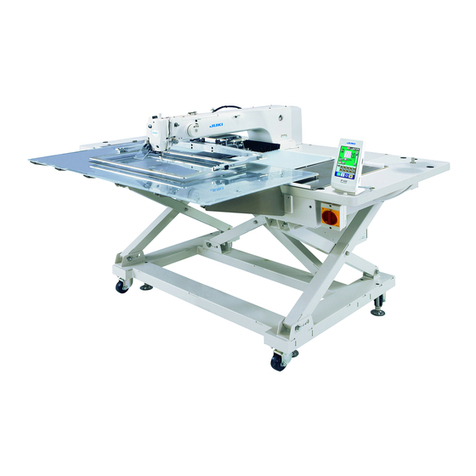
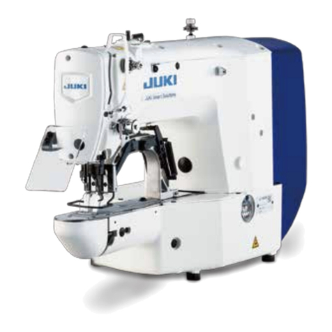
JUKI AMS-210EN Series Quick start guide

40087239
No.E388-00
ENGINEER’S MANUAL
Computer-controlled, Cycle Machine
With Input Function
AMS-210EN Series
®

PREFACE
This Engineer’s Manual is written for the technical personnel who are responsible for the service and maintenance
of the machine.
The Instruction Manual for these machines intended for the maintenance personnel and operators at an apparel
factory contains operating instructions in detail.
It is advisable to use the Instruction Manual and Parts List together with this Engineer's Manual when carrying out
the maintenance of these machines.
This manual gives the "StandardAdjustment" on the former section under which the most basic adjustment value
is described and on the latter section the "Results of Improper Adjustment" under which stitching errors and
troubles arising from mechanical failures and "How To Adjust" are described.

CONTENTS
1. Specifications ........................................................................................................ 1
2. Configuration........................................................................................................... 2
(1) Names of main unit .................................................................................................................. 2
(2) IP-420 operation panel............................................................................................................. 3
3. Standard adjustment .............................................................................................. 5
(1) Main shaft connection/disconnection .................................................................................. 5
(2) Removal of main shaft motor and coupling......................................................................... 7
(3) Crank rod connection/disconnection ................................................................................... 9
(4) Crank balancer positioning ................................................................................................. 11
(5) Adjustment of intermediate presser cam ........................................................................... 13
(6) Adjustment of intermediate presser bar............................................................................. 13
(7) Intermediate presser variable connection /disconnection ............................................... 15
(8) Intermediate presser variable adjustments........................................................................ 17
(9) Intermediate presser drivie arm .......................................................................................... 19
(10)Lower shaft backlash adjustment and connection/disconnection .................................. 21
(11) Oscillator gear positioning .................................................................................................. 21
(12)Adjustment of hook oil amount........................................................................................... 23
(13)Shuttle connection / disconnection and oil wick piping................................................... 23
(14)Adjusting the height of the needle bar ............................................................................... 25
(15)Hook adjustment................................................................................................................... 27
(16) Thread trimmer presser lifter cam connection/disconnection ........................................ 29
(17) Thread trimmer and presser origin sensor adjustment ................................................... 29
(18) Adjustment of the moving knife and counter knife position............................................ 31
(19) Floating amount of the thread tension disk ...................................................................... 31
(20) Second thread tension connection / disconnection......................................................... 33
(21) AT unit connection / disconnection.................................................................................... 35
(22) Wiper adjustment ................................................................................................................. 37
(23) Adjusting the pre-load of the X-Y table .............................................................................. 39
(24) Adjustment of the tension of the X timing belt.................................................................. 41
(25) Adjustment to positions of X-motor and Y-motor (Backlash adjustment to gear)......... 43
(26) Adjusting of the presser lower arm (Motor type only)...................................................... 43
(27) Adjustment when the presser plate sheet is replaced (Motor type only) ....................... 45
(28) Height of the slider and pasting of the presser plate sheet
(Pneumatic type only) .......................................................................................................... 47
(29) Adjusting the speed of the work clamp feet (Pneumatic type only)................................ 49
(30) Making the origin setting gauge ......................................................................................... 51
(31) Adjusting the X origin sensor ............................................................................................. 51
(32) Adjusting the Y origin sensor ............................................................................................. 53
(33) Adjustment of the bobbin winder driving wheel position ................................................ 55
(34) Adjusting the bobbin winder amount................................................................................. 55
(35) Adjustment of the shuttle upper spring and lower thread holder position .................... 57
(36) Shuttle felt............................................................................................................................. 57
(37) Shape of the shuttle race ring.............................................................................................59

(38) Adjustment of thread take-up spring ................................................................................. 59
(39) Needle thread clamp device connection/disconnection .................................................. 61
(40) Adjusting the needle thread clamp notch.......................................................................... 63
(41) Adjusting the needle thread clamp sensor........................................................................ 65
4. Memory switch ...................................................................................................... 67
(1) Start and change .................................................................................................................... 67
(2) Function list............................................................................................................................ 68
5. Supplemental remarks of each function number and
explanation of each function ............................................................................... 85
(1) Feeding frame operational sequence setup ........................................................................ 85
(2) Fixed refuge position setup .................................................................................................. 90
(3) Bank function setup............................................................................................................... 91
(4) Port I/O setup.......................................................................................................................... 94
(5) Simplified program setup....................................................................................................107
(6) Version display..................................................................................................................... 120
(7) Keylock setup....................................................................................................................... 121
(8) Customize function setting of key lock ............................................................................. 123
(9) Communication screens of the maintenance personnel level (Program rewrite) ......... 130
(10) Information screen at the maintenance personnel level ................................................ 134
(11) Test sewing function ......................................................................................................... 136
6. Test mode ........................................................................................................... 139
7. Printed wiring board and dip switch................................................................ 155
(1) Various printed wiring boards ............................................................................................ 155
(2) Dipswitch setup.................................................................................................................... 163
8. Table of exchanging gauge parts according to sewing specifications and
needle size used ................................................................................................ 164
9. Option list........................................................................................................... 165
(1) Method of pedal switch cable set connections................................................................. 172
(2) Method of mechanical valve unit connections.................................................................. 174
10.Maintenance ....................................................................................................... 175
(1) Replacing the fuse ............................................................................................................... 175
(2) Changing the voltage specification.................................................................................... 176
(3) Greasing • lock-tight parts .................................................................................................. 177
(4) Parts to which grease • lock-tight is applied ..................................................................... 178
(5) Replenishing the designated places with grease ............................................................. 186
11. Error code list .................................................................................................... 191
12. Message list....................................................................................................... 199

13.Troubles and corrective measures .................................................................. 203
(1) Mechanical parts .................................................................................................................. 203
(2) Sewing conditions ............................................................................................................... 207
(3) Electrical components......................................................................................................... 216
14.Circuit diagrams ................................................................................................ 226
(1) Block diagram ..................................................................................................................... 226
(2) Power supply circuit diagram A ........................................................................................ 227
(3) Power supply circuit diagram B ........................................................................................ 228
(4) Power supply circuit diagram C ........................................................................................ 229
(5) Servo motor circuit diagram.............................................................................................. 230
(6) Sensor-pedal circuit diagram ............................................................................................ 231
(7) MAIN•PANEL board circuit diagram ................................................................................. 232
(8) Motor•solenoid circuit diagram......................................................................................... 233
(9) Air system circuit diagram................................................................................................. 234
15.Drawing of the table........................................................................................... 235
Other manuals for AMS-210EN Series
1
Table of contents
Other JUKI Sewing Machine manuals

JUKI
JUKI SC-920 User manual

JUKI
JUKI SADE User manual

JUKI
JUKI DU-1181N User manual

JUKI
JUKI DLU-5490N User manual

JUKI
JUKI MO-6000 Series User manual

JUKI
JUKI APW-896N/IP-420 User manual

JUKI
JUKI AMB-289/IP-420 User manual

JUKI
JUKI MO-50eN User manual

JUKI
JUKI MB-1373 User manual

JUKI
JUKI MO-6000 Series User manual

JUKI
JUKI Union Special 36200 CLASS Series Setup guide

JUKI
JUKI HZL-G Series User manual

JUKI
JUKI IP-110 Type F User manual

JUKI
JUKI LU-1510 Quick start guide

JUKI
JUKI MO-734DE User manual

JUKI
JUKI DLU-5494N-7 User manual

JUKI
JUKI L-1C User manual

JUKI
JUKI MB-372 User manual

JUKI
JUKI PLK-J6040 User manual

JUKI
JUKI MF-7700D Series User manual