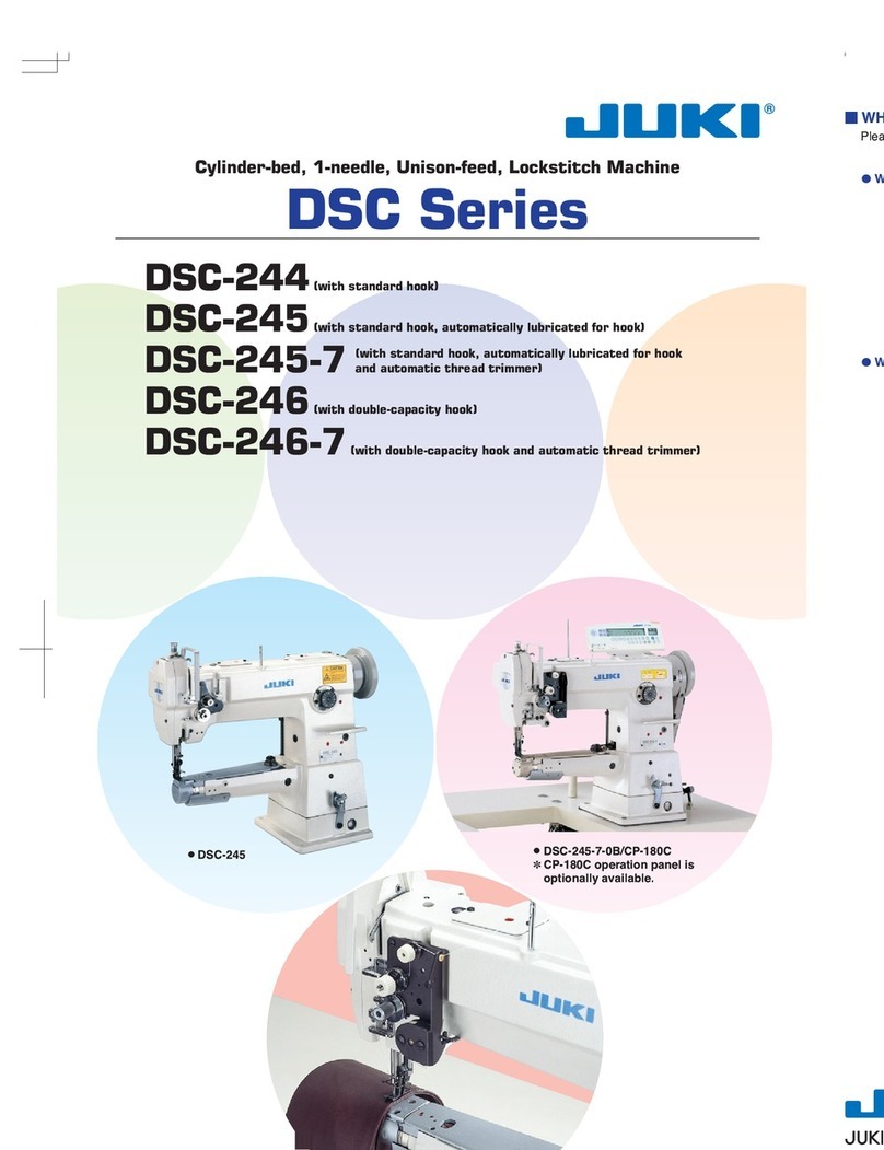
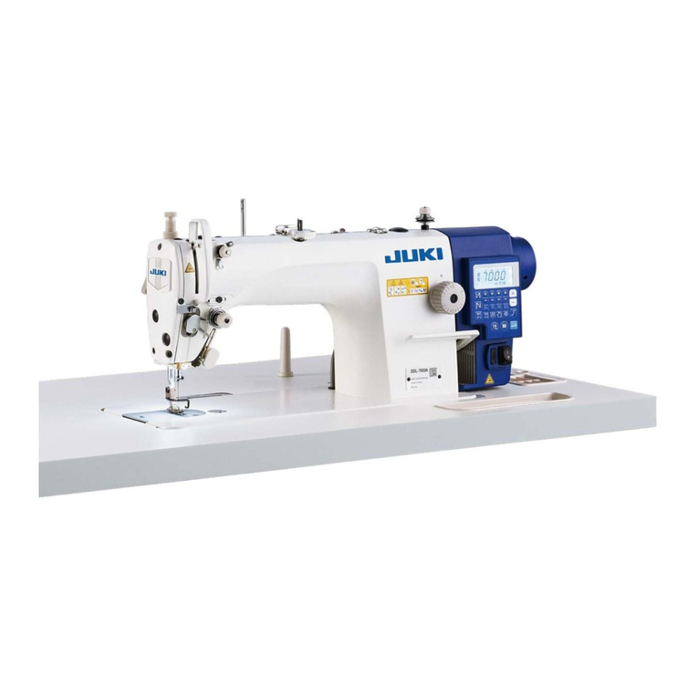
JUKI DSC-245 User manual

Copyright © 2012-2013 JUKI CORPORATION
• All rights reserved throughout the world.
Please do not hesitate to contact our distributors or agents in your area for further information when necessary.
*The description covered in this instruction manual is subject to change for improvement of the
commodity without notice.
13 · 09 Printed in Japan
SEWING MACHINERY BUSINESS UNIT
2-11-1, TSURUMAKI, TAMA-SHI,
TOKYO, 206-8551, JAPAN
PHONE : (81)42-357-2371
FAX : (81)42-357-2274
http://www.juki.com
No.02
40092228
INSTRUCTION MANUAL
DSC-245,-4,-7
DSC-245V,-4,-7
NOTE : Read safety instructions carefully and understand them before using.
Retain this Instruction Manual for future reference.

日本語
日本語

i
i
For the sewing machine, automatic machine and ancillary devices (hereinafter collectively referred to as
"machine"), it is inevitable to conduct sewing work near moving parts of the machine. This means that there
is always a possibility of unintentionally coming in contact with the moving parts. Operators who actually
operate the machine and maintenance personnel who are involved in maintenance and repair of the machine
are strongly recommended to carefully read to fully understand the following SAFETY PRECAUTIONS
before using/maintaining the machine. The content of the SAFETY PRECAUTIONS includes items which
are not contained in the specications of your product.
The risk indications are classied into the following three different categories to help understand the meaning
of the labels. Be sure to fully understand the following description and strictly observe the instructions.
Warning label
❶
❷
❸
❶•Thereisthepossibilitythatslighttoseriousinjuryordeathmaybecaused.
•Thereisthepossibilitythatinjurymaybecausedbytouchingmovingpart.
❷•Toperformsewingworkwithsafetyguard.
•Toperformsewingworkwithsafetycover.
•Toperformsewingworkwithsafetyprotectiondevice.
❸•BesuretoturnthepowerOFFbeforecarryingout"machine-headthreading",
"needlechanging","bobbinchanging"or"oilingandcleaning".
❸
❷
❶
Electrical-shock
dangerlabel
DANGER :
Thisindicationisgivenwherethereisanimmediatedangerofdeathorserousinjuryifthepersoninchargeoranythird
partymishandlesthemachineordoesnotavoidthedangeroussituationwhenoperatingormaintainingthemachine.
WARNING :
Thisindicationisgivenwherethereisapotentialityfordeathorseriousinjuryifthepersoninchargeoranythird
partymishandlesthemachineordoesnotavoidthedangeroussituationwhenoperatingormaintainingthemachine.
CAUTION :
Thisindicationisgivenwherethereisadangerofmediumtominorinjuryifthepersoninchargeoranythirdpar-
tymishandlesthemachineordoesnotavoidthedangeroussituationwhenoperatingormaintainingthemachine.
Itemsrequiringspecialattention.
Pictorialwarningindication
Thereisariskofinjuryifcontact-
ingamovingsection.
Pictorialwarning
indication
Beawarethatholdingthesewing
machineduringoperationcan
hurtyourhands.
Thereisariskofelectricalshockif
contactingahigh-voltagesection.
Thereisariskofentanglementin
thebeltresultingininjury.
Thereisariskofaburnifcontact-
ingahigh-temperaturesection.
Thereisariskofinjuryifyou
touchthebuttoncarrier.
Beawarethateyedeciencycan
becausedbylookingdirectlyatthe
laserbeam.
Indicationlabel
Thecorrectdirectionisindicated.
Thereisariskofcontactbetween
yourheadandthesewingma-
chine.
Connectionofaearthcableis
indicated.
TO ENSURE SAFE USE OF YOUR SEWING MACHINE
(I)Explanationofrisklevels
(II)
Explanationofpictorialwarningindicationsandwarninglabels

ii
ii
SAFETY PRECAUTIONS
1. Whenitisnecessarytoopenthecontrolboxcontainingelectricalparts,besuretoturnthepower
offandwaitforveminutesormorebeforeopeningthecoverinordertopreventaccidentleadingto
electricalshock.
Accidentmeans"tocause
personalinjuryordeathor
damagetoproperty."
DANGER
CAUTION
Basicprecaution
1. Besuretoreadtheinstructionmanualandotherexplanatorydocumentssuppliedwithaccessoriesof
themachinebeforeusingthemachine.Carefullykeeptheinstructionmanualandtheexplanatorydocu-
mentsathandforquickreference.
2. Thecontentofthissectionincludesitemswhicharenotcontainedinthespecicationsofyourproduct.
3. Besuretowearsafetygogglestoprotectagainstaccidentcausedbyneedlebreakage.
4. Thosewhouseaheartpacerhavetousethemachineafterconsultationwithamedicalspecialist.
Safetydevicesandwarninglabels
1. Besuretooperatethemachineafterverifyingthatsafetydevice(s)iscorrectlyinstalledinplaceand
worksnormallyinordertopreventaccidentcausedbylackofthedevice(s).
2. Ifanyofthesafetydevicesisremoved,besuretoreplaceitandverifythatitworksnormallyinorderto
preventaccidentthatcanresultinpersonalinjuryordeath.
3. Besuretokeepthewarninglabelsadheredonthemachineclearlyvisibleinordertopreventaccident
thatcanresultinpersonalinjuryordeath.Ifanyofthelabelshasstainedorcomeunstuck,besureto
changeitwithanewone.
Applicationandmodication
1. Neverusethemachineforanyapplicationotherthanitsintendedoneandinanymannerotherthanthat
prescribedintheinstructionmanualinordertopreventaccidentthatcanresultinpersonalinjuryor
death.JUKIassumesnoresponsibilityfordamagesorpersonalinjuryordeathresultingfromtheuseof
themachineforanyapplicationotherthantheintendedone.
2. Nevermodifyandalterthemachineinordertopreventaccidentthatcanresultinpersonalinjuryor
death.JUKIassumesnoresponsibilityfordamagesorpersonalinjuryordeathresultingfromthema-
chinewhichhasbeenmodiedoraltered.
Educationandtraining
1. Inordertopreventaccidentresultingfromunfamiliaritywiththemachine,themachinehastobeused
onlybytheoperatorwhohasbeentrained/educatedbytheemployerwithrespecttothemachineoper-
ationandhowtooperatethemachinewithsafetytoacquireadequateknowledgeandoperationskill.To
ensuretheabove,theemployerhastoestablishaneducation/trainingplanfortheoperatorsandedu-
cate/trainthembeforehand.
Itemsforwhichthepowertothemachinehastobeturnedoff
Turningthepoweroff: Turningthepowerswitchoff,thenremovingthepowerplugfromtheoutlet.
Thisappliestothefollowing.
1. Besuretoimmediatelyturnthepoweroffifanyabnormalityorfailureisfoundorinthecaseofpower
failureinordertoprotectagainstaccidentthatcanresultinpersonalinjuryordeath.
2. Toprotectagainstaccidentresultingfromabruptstartofthemachine,besuretocarryoutthefollow-
ingoperationsafterturningthepoweroff.Forthemachineincorporatingaclutchmotor,inparticular,
besuretocarryoutthefollowingoperationsafterturningthepoweroffandverifyingthatthemachine
stopscompletely.
2-1. Forexample,threadingthepartssuchastheneedle,looper,spreaderetc.whichhavetobethread-
ed,orchangingthebobbin.
2-2. Forexample,changingoradjustingallcomponentpartsofthemachine.
2-3. Forexample,wheninspecting,repairingorcleaningthemachineorleavingthemachine.
3. Besuretoremovethepowerplugbyholdingtheplugsectioninsteadofthecordsectioninordertopre-
ventelectrical-shock,earth-leakageorreaccident.
4. Besuretoturnthepoweroffwheneverthemachineisleftunattendedbetweenworks.
5. Besuretoturnthepoweroffinthecaseofpowerfailureinordertopreventaccidentresultingofbreak-
ageofelectricalcomponents.
– 19 –
29.TROUBLES AND CORRECTIVE MEASURES
Trouble Cause Corrective measures
1.Thread breakage
(Thread frays or
wears out.)
①The thread path,needle point,hook point or bobbin
case positioning nger has scratches.
○ Remove the scratches on the hook point using a ne sand
paper. Buff the bobbin case positioning nger.
②The needle thread tension is too high. ○ Properly adjust the needle thread tension.
③The needle hits the hook point. ○ See "17.NEEDLE-TO-HOOK RELATIONSHIP".
④Lubrication to hook is inadequate. ○ Properly adjust the lubrication. See "4.LUBRICATION".
(Needle thread
remains 2 to 3 cm on
the wrong side of the
cloth.)
⑤The needle thread tension is too low. ○ Properly adjust the needle thread tension.
⑥The thread take-up spring has an excessively high
tension while it has an excessively small stroke.
○ Decrease the tension,and increase the stroke.
⑦The timing between the needle and hook is too
early or late.
○ See "17.NEEDLE-TO-HOOK RELATIONSHIP".
⑧The bobbin races frequently. ○ Increase the spring pressure. Alternatively,reduce the
thread trimming speed.
2.Stitch skipping ①The clearance between the needle and the hook
point is too large.
○ See "17.NEEDLE-TO-HOOK RELATIONSHIP".
②The timing between the needle and the hook point
is too early or late.
○ See "17.NEEDLE-TO-HOOK RELATIONSHIP".
③The presser foot pressure is too low. ○ Increase the presser foot pressure.
④The clearance between the top edge of the needle
eyelet and the hook point is not correct.
○ See "17.NEEDLE-TO-HOOK RELATIONSHIP".
⑤The size of the needle is wrong. ○ Replace the needle by one which is one
grade thicker.
⑥ A synthetic ber thread or thin thread is used. ○ Wind the thread round the needle as illustrat-
ed.
3.Loose stitches ①The thread has not been passed through the notch
of the bobbin case tension spring.
○ Properly thread the bobbin case.
② The thread path is poorly nished. ○ Grind it using a ne sand paper or a buff.
③The bobbin does not rotate smoothly. ○ Replace the bobbin or hook.
④The bobbin thread tension is too low. ○ Properly adjust the tension.
⑤The bobbin thread has been wound too tight. ○ Properly adjust the needle thread tension.
⑥An untwisted synthetic thread is used. ○ Slightly reduce the sewing speed.(2,000 sti/min)
⑦A coated cloth or nylon yarn is used. ○ Use a ball-point needle..
4.A few stitches are
skipped.
①The bobbin thread is too short. ○ Replace the bobbin by a standard one (aluminum).
②The bobbin thread breaks. ○ Decrease the bobbin thread tension and the thread trim-
ming speed.
③A nylon thread is used when sewing lightweight
material.
○ Use the soft start function.
5.The thread slips off ①The tension of the auxiliary thread tension ○ Decrease the tension.
②Thread take-up timing is too early. ○ See "21.ADJUSTING THE THREAD TRIMMING CAM".
③Returning force of the thread take-up spring is
excessively strong.
○ See "9.THREAD THE MACHINE HEAD". Replace the
thread guide with an appropriate one.
④The feed dog and walking foot trims thread. ○ Replace the walking foot with an appropriate one.
⑤Actuating quantity of the picker is inadequate. ○ See "24.ADJUSTING THE OPERATING STROKE OF
THE PICKER".
6.The needle thread
cannot be trimmed.
(The bobbin thread
can be trimmed.)
①The last stitch has been skipped.(The clearance
between the needle and the hook is too large.)
○ See "17.NEEDLE-TO-HOOK RELATIONSHIP".
7.Both needle and bob-
bin threads cannot be
trimmed.
①The thread trimming timing is wrong. ○ See "21.ADJUSTING THE THREAD TRIMMING TIMING".
②The knife has been damaged. ○ Replace the knife.
③The knife pressure is inadequate. ○ Increase the knife pressure.
④The movement of the rotary knife is short. ○ See "23.ADJUSTING MAX. MOVING POSITION OF THE
ROTARY KNIFE".
⑤The thread trimming solenoid fails to work. ○ Check the motor solenoid for proper operation.
8.Thread cannot be
trimmed sharply.
①The thread trimming timing is wrong. ○ See "22.ADJUSTING THE THREAD TRIMMING TIMING".
②The knife pressure is inadequate. ○ Increase the knife pressure.
③The knife blade is blunt. ○ Replace the knife.
9.Chain off thread
doesn't come out.
①Breakage due to thread frayed caused by standing
and apping of thread.
○ Use the furnished thread guide and the presser foot with a
slot.
②Breakage between the bottom face of the presser
foot and the contact face with throat plate.
10.Stepped part is
clogged.
①The presser foot slips when riding on the stepped
part.
○ Use B15242450AB presser foot (option) and B147024500B
walking foot (option).
11.When the alternate lift
is increased,the pitch
cannot be achieved
as per the scale.
①Sewing speed is too fast,resulting in reducing the
feed force.
○ Reduce the sewing speed.

– 18 –
1 . Use the 3-phase 400 W AC clutch motor.
2 . Use an M type V belt.
3 . The following table shows the relationship among the motor pulley and the sewing speed.
28.MOTOR PULLEY AND SEWING SPEED (DSC-245, DSC-245V)
Model Sewing speed Effective diameter
of handwheel
Number
of poles Frequency Rotational
speed of motor
Effective diameter
of motor pulley
DSC-245
DSC-245V 2,200 sti/min ø76.0 4 50Hz 1430 rpm ø115
60Hz 1715 rpm ø95
(Caution)
The effective diameter of the motor pulley is obtained by subtracting 5 mm from the outside diameter.
iii
iii
PRECAUTIONSTOBETAKENINVARIOUSOPERATIONSTAGES
Transportation
1. Besuretoliftandmovethemachineinasafemannertakingthemachineweightinconsideration.Refer
tothetextoftheinstructionmanualforthemassofthemachine.
2. Besuretotakesufcientsafetymeasurestopreventfallingordroppingbeforeliftingormovingthe
machineinordertoprotectagainstaccidentthatcanresultinpersonalinjuryordeath.
3. Oncethemachinehasbeenunpacked,neverre-packitfortransportationtoprotectthemachineagainst
breakageresultingfromunexpectedaccidentordropping.
Unpacking
1. Besuretounpackthemachineintheprescribedorderinordertopreventaccidentthatcanresultin
personalinjuryordeath.Inthecasethemachineiscrated,inparticular,besuretocarefullychecknails.
Thenailshavetoberemoved.
2. Besuretocheckthemachineforthepositionofitscenterofgravityandtakeitoutfromthepackage
carefullyinordertopreventaccidentthatcanresultinpersonalinjuryordeath.
Installation
(I)Tableandtablestand
1. BesuretouseJUKIgenuinetableandtablestandinordertopreventaccidentthatcanresultinper-
sonalinjuryordeath.IfitisinevitabletouseatableandtablestandwhicharenotJUKIgenuineones,
selectthetableandtablestandwhichareabletosupportthemachineweightandreactionforceduring
operation.
2. Ifcastersarettedtothetablestand,besuretousethecasterswithalockingmechanismandlock
themtosecurethemachineduringtheoperation,maintenance,inspectionandrepairinordertoprevent
accidentthatcanresultinpersonalinjuryordeath.
(II)Cableandwiring
1. Besuretopreventanextraforcefrombeingappliedtothecableduringtheuseinordertoprevent
electrical-shock,earth-leakageorreaccident.Inaddition,ifitisnecessarytocableneartheoperating
sectionsuchastheV-belt,besuretoprovideaspaceof30mmormorebetweentheoperatingsection
andthecable.
2. Besuretoavoidstarburstconnectioninordertopreventelectrical-shock,earth-leakageorreaccident.
3. Besuretosecurelyconnecttheconnectorsinordertopreventelectrical-shock,earth-leakageorre
accident.Inaddition,besuretoremovetheconnectorwhileholdingitsconnectorsection.
(III)Grounding
1. Besuretohaveanelectricalexpertinstallanappropriatepowerpluginordertopreventaccidentcaused
byearth-leakageordielectricstrengthvoltagefault.Inaddition,besuretoconnectthepowerplugtothe
groundedoutletwithoutexceptions.
2. Besuretogroundtheearthcableinordertopreventaccidentcausedbyearthleakage.
(IV)Motor
1. Besuretousethespeciedratedmotor(JUKIgenuineproduct)inordertopreventaccidentcausedby
burnout.
2. Ifacommerciallyavailableclutchmotorisusedwiththemachine,besuretoselectonewithanentan-
glementpreventivepulleycoverinordertoprotectagainstbeingentangledbytheV-belt.
Beforeoperation
1. Besuretomakesurethattheconnectorsandcablesarefreefromdamage,dropoutandloosenessbe-
foreturningthepoweroninordertopreventaccidentresultinginpersonalinjuryordeath.
2. Neverputyourhandintothemovingsectionsofthemachineinordertopreventaccidentthatcanresult
inpersonalinjuryordeath.
Inaddition,checktobesurethatthedirectionofrotationofthepulleyagreeswiththearrowshownon
pulley.
3. Ifthetablestandwithcastersisused,besuretosecurethetablestandbylockingthecastersorwith
adjusters,ifprovided,inordertoprotectagainstaccidentcausedbyabruptstartofthemachine.
Duringoperation
1. Besurenottoputyourngers,hairorclothingclosetothemovingsectionssuchasthehandwheel,
handpulleyandmotororplacesomethingnearthosesectionswhilethemachineisinoperationinorder
topreventaccidentcausedbyentanglementthatcanresultinpersonalinjuryordeath.
2. Besurenottoplaceyourngersnearthesurroundareaoftheneedleorinsidethethreadtake-uplever
coverwhenturningthepoweronorwhilethemachineisinoperationinordertopreventaccidentthat
canresultinpersonalinjuryordeath.
3. Themachinerunsatahighspeed.Neverbringyourhandsnearthemovingsectionssuchaslooper,
spreader,needlebar,hookandclothtrimmingknifeduringoperationinordertoprotectyourhands
againstinjury.Inaddition,besuretoturnthepoweroffandchecktobesurethatthemachinecomplete-
lystopsbeforechangingthethread.
4. Becarefulnottoallowyourngersoranyotherpartsofyourbodytobecaughtbetweenthemachine
andtablewhenremovingthemachinefromorreplacingitonthetableinordertopreventaccidentthat
canresultinpersonalinjuryordeath.

iv
iv
5. Besuretoturnthepoweroffandchecktobesurethatthemachineandmotorcompletelystopbeforere-
movingthebeltcoverandV-beltinordertopreventaccidentcausedbyabruptstartofthemachineormotor.
6. Ifaservomotorisusedwiththemachine,themotordoesnotproducenoisewhilethemachineisatrest.
Besurenottoforgettoturnthepoweroffinordertopreventaccidentcausedbyabruptstartofthemotor.
7. Neverusethemachinewiththecoolingopeningofthemotorpowerboxshieldedinordertopreventre
accidentbyoverheat.
Lubrication
1. BesuretouseJUKIgenuineoilandJUKIgenuinegreasetothepartstobelubricated.
2. Iftheoiladheresonyoureyeorbody,besuretoimmediatelywashitoffinordertopreventinamma-
tionorirritation.
3. Iftheoilisswallowedunintentionally,besuretoimmediatelyconsultamedicaldoctorinordertopre-
ventdiarrheaorvomiting.
Maintenance
1. Inpreventionofaccidentcausedbyunfamiliaritywiththemachine,repairandadjustmenthastobe
carriedoutbyaservicetechnicianwhoisthoroughlyfamiliarwiththemachinewithinthescopedened
intheinstructionmanual.BesuretouseJUKIgenuinepartswhenreplacinganyofthemachineparts.
JUKIassumesnoresponsibilityforanyaccidentcausedbyimproperrepairoradjustmentortheuseof
anypartotherthanJUKIgenuineone.
2. Inpreventionofaccidentcausedbyunfamiliaritywiththemachineorelectrical-shockaccident,besure
toaskanelectricaltechnicianofyourcompanyorJUKIordistributorinyourareaforrepairandmainte-
nance(includingwiring)ofelectricalcomponents.
3. Whencarryingoutrepairormaintenanceofthemachinewhichusesair-drivenpartssuchasanaircyl-
inder,besuretoremovetheairsupplypipetoexpelairremaininginthemachinebeforehand,inorderto
preventaccidentcausedbyabruptstartoftheair-drivenparts.
4. Besuretocheckthatscrewsandnutsarefreefromloosenessaftercompletionofrepair,adjustment
andpartreplacement.
5. Besuretoperiodicallycleanupthemachineduringitsdurationofuse.Besuretoturnthepoweroff
andverifythatthemachineandmotorstopcompletelybeforecleaningthemachineinordertoprevent
accidentcausedbyabruptstartofthemachineormotor.
6. Besuretoturnthepoweroffandverifythatthemachineandmotorstopcompletelybeforecarryingout
maintenance,inspectionorrepairofthemachine.(Forthemachinewithaclutchmotor,themotorwill
keeprunningforawhilebyinertiaevenafterturningthepoweroff.So,becareful.)
7. Ifthemachinecannotbenormallyoperatedafterrepairoradjustment,immediatelystopoperationand
contactJUKIorthedistributorinyourareaforrepairinordertopreventaccidentthatcanresultinper-
sonalinjuryordeath.
8. Ifthefusehasblown,besuretoturnthepoweroffandeliminatethecauseofblowingofthefuseand
replacetheblownfusewithanewoneinordertopreventaccidentthatcanresultinpersonalinjuryor
death.
9. Besuretoperiodicallycleanuptheairventofthefanandinspecttheareaaroundthewiringinorderto
preventreaccidentofthemotor.
Operatingenvironment
1. Besuretousethemachineundertheenvironmentwhichisnotaffectedbystrongnoisesource(electro-
magneticwaves)suchasahigh-frequencywelderinordertopreventaccidentcausedbymalfunctionof
themachine.
2. Neveroperatethemachineinanyplacewherethevoltageuctuatesbymorethan"ratedvoltage±10%"
inordertopreventaccidentcausedbymalfunctionofthemachine.
3. Besuretoverifythattheair-drivendevicesuchasanaircylinderoperatesatthespeciedairpressure
beforeusingitinordertopreventaccidentcausedbymalfunctionofthemachine.
4. Tousethemachinewithsafety,besuretouseitundertheenvironmentwhichsatisesthefollowing
conditions:
Ambienttemperatureduringoperation 5°Cto35°C
Relativehumidityduringoperation 35%to85%
5. Dewcondensationcanoccurifbringingthemachinesuddenlyfromacoldenvironmenttoawarmone.
So,besuretoturnthepoweronafterhavingwaitedforasufcientperiodoftimeuntilthereisnosign
ofwaterdropletinordertopreventaccidentcausedbybreakageormalfunctionoftheelectricalcompo-
nents.
6. Besuretostopoperationwhenlightningashesforthesakeofsafetyandremovethepowerplugin
ordertopreventaccidentcausedbybreakageormalfunctionoftheelectricalcomponents.
7. Dependingontheradiowavesignalcondition,themachinemaygeneratenoiseintheTVorradio.Ifthis
occurs,usetheTVorradiowithkeptwellawayfromthemachine.
8. Inordertoensuretheworkenvironment,locallawsandregulationsinthecountrywherethesewing
machineisinstalledshallbefollowed.
Inthecasethenoisecontrolisnecessary,anearprotectororotherprotectivegearshouldbewornac-
cordingtotheapplicablelawsandregulations.
9. Disposalofproductsandpackagesandtreatmentofusedlubricatingoilshouldbecarriedoutproperly
accordingtotherelevantlawsofthecountryinwhichthesewingmachineisused.
– 17 –
2. Installation process
1) Fit spring over screw . In this state, x
feed bar hinge stud .
2) Attach feed driving pin in place.
3) Attach feed bar block A on feed bar oscil-
lating arm .
4) Attach feed bar block shaft on feed bar .
5) Attach feed bar block B in feed bar block
shaft using E ring .
6) Attach feed on feed bar with feed set-
screw .
7) Attach feed bar block shaft and feed bar
on which feed has been attached in place
on feed bar hinge stud .
8) Install spring support shaft in place.
9) Tighten feed setscrew to allow the needle
to come just at the center of the needle hole
in the feed .
10) Top cover spring of the bed,feed bar shaft
cover and screw of the feed bar shaft
cover in place.
11) Fix top cover of the bed by tightening
screw in the top cover of the bed.
12) Attach throat plate in place and x it using
screw of the throat plate.
13) Install presser foot (asm.) and walking foot
in place.
(Caution)
1.The parts attached with an asterisk ( * ) are the exclusive parts for the DSC-245V-4 or -7.
2.The feed driving pin has engraved marker lines. Use the pin which has many marker lines to raise the feed dog,or
use the pin with less marker lines to lower it.
Note No. Part No. Part Name Q'ty Remarks
22 B15242450A0 Presser foot (asm.) 1
23 B1470245000 Walking foot 1
24 SS2110915SP Screw in throat plate 2 11/64 40 thread ridges, L=8.5
25 B1105245000 Throat plate 1
* D1105245E00 Throat plate 1
26 SS2090710TP Screw in top cover of bed 1 9/64 40 thread ridges, L=7
27 B1173245000 Top cover of bed 1
* D1173245E00 Top cover of bed 1
28 B1175245000 Spring of top cover of bed 1
29 B1613245000 Feed 1
* D1613245E0A Feed 1
30 B1645245000 Feed bar block 1
31 RE0300000K0 E ring 1
32 B1644245000 Feed bar block B 1
33 B1643145000 Feed bar block A 1
34 B163224500C Feed driving pin 1 Selective part (caution 2)
35 B1641245000 Feed bar hinge stud screw 2
36 B1642245000 Feed bar hinge stud screw spring 2
List of parts to be replaced
Part No. B163224500A B163224500B B163224500C B163224500D B163224500E
Length(mm) 5.7±0.05 5.9±0.05 6.1±0.05 6.3±0.05 6.5±0.05
Number of marker lines 1 2 3 4 5
– 16 –
27.HOW TO CHANGE FROM HORIZONTAL FEED TO ELLIPTICAL FEED
(Caution) 1.The parts attached with an asterisk(*) are the exclusive parts for the DSC-245V-4 or 7.
2.★marks mean the parts used succeedingly after replacement.
1. Removing process
1) Remove presser foot (asm.) and walking
foot .
2) Loosen throat plate setscrew and remove
throat plate .
3) Loosen screw in the feed bar shaft cov-
er,and remove top cover ❹of the bed,top
cover spring ❾of the bed and cover of
feed bar shaft.
4) Remove the feed unit with tape guide
❼,screw ❽in the tape guide,screws ❺in
the binder and nuts ❻of the screws in the
binder attached on top cover ❹of the bed.
5) Remove spring support shaft .
6) Remove feed bar .(At this time,it should
be removed with feed ❸,feed bar block
shaft ❷attached in place.)
7) Remove feed bar block ❶from feed bar
oscillating arm .
8)
Remove feed bar block shaft
❷
from feed bar
.
9) Loosen screws in the feed,and remove
feed ❸.
10) Remove feed bar stud ,screw .
This model can be changed to elliptical feed by changing the related parts accordingly.
List of parts to be replaced
Note No. Part No. Part Name
Q'ty
Remarks
1 MAQ09210000 Feed bar block 1
2 MAQ09211000 Feed bar block shaft 1
* MAQ09411000 Feed bar block shaft 1
3 MAN10451000 Feed 1
* 21305206 Feed 1
4 MAQ09202000 Top cover of bed 1
* MAQ09402000 Top cover of bed 1
5 MAQ09204000 Screw in binder 2 11/64 40 thread ridges
6 MAQ09205000 Nut of screw in binder 2 11/64 40 thread ridges
7 MAQ09206000 Tape guide 1
8 SS7110510SP Screw in tape guide 1 11/64 40 thread ridges, L=5
9 MAQ09203000 Spring of top cover of bed 1
* 10 MAQ09201000 Throat plate 1
MAQ09401000 Throat plate 1
11 SS2110930SP Screw in throat plate 2 11/64 40 thread ridges, L=8.5
12 MAQ093080A0 Presser foot (asm.) 1
★13 MAN10452000 Walking foot 1
★14 B1653245000
Screw in the feed bar shaft cover
1 9/64 40 thread ridges, L=10
★15 B1640245000 Cover of feed bar shaft 1
★16 B1638245000 Spring support shaft 1
★17 D1606245E00 Feed bar 1
★18 B1652245000 Screw in feed 2 1/8 44 thread ridges, L=3.7
19 B1603245000 Feed bar oscillating arm 1
20 B1639245000 Feed bar hinge stud 1
21 SS7110910SP Feed bar hinge stud screw 2
WARNING :
Turn OFF the power before starting the work so as to prevent accidents caused by abrupt start of the
sewing machine.
v
CAUTION :
Note that safety devices such as “eye guard”, “nger guard”, etc. may be omitted from the
illustrations in this Instruction Manual for easy explanation.
When operating the machine, be sure not to remove these safety devices.
1. For the safety, never operate the sewing machine with the ground wire for the
power supply removed.
2. Be sure to turn OFF the power switch in prior when connecting/disconnecting the
power plug.
3. When thunders occurs, stop the work for the safety and disconnect the power plug.
4. When the sewing machine is suddenly moved from a cold place to a warm place,
there is a case where dew condensation may occur. Turn ON the power after there
is no worry of the drop of water.
5. To prevent res, periodically draw out the power plug from the plug socket and
clean the root of the pins and the space between pins.
6. The hook rotates at a high speed while the machine is in operation.
To prevent possible injury to hands, be sure to keep your hands away from the
vicinity of the hook during operation. In addition, be sure to turn OFF the power to
the machine when replacing the bobbin.
7. To avoid possible accidents due to abrupt start of the machine, be sure to turn OFF
the power to the machine.
8. Be careful of handling this product so as not to pour water or oil, shock by dropping,
and the like since this product is a precision instrument.
9. When tilting or returning the sewing machine to the home position, hold the upper
side of the machine head with both hands and perform the work quietly so that
ngers or the like are not caught in the machine.
1. To avoid personal injury, never put your ngers under the needle when you turn ON
the power switch or operate the sewing machine.
2. To avoid personal injury, never put your ngers into the thread take-up cover while
the sewing machine is in operation.
3. Turn OFF the power switch when tilting the machine head, or removing the belt
cover or the V belts.
4. To prevent possible personal injury caused by being caught in the machine, keep
your ngers, head and clothes away from the handwheel and the thread take-up
while the sewing machine is in operation. In addition, place nothing around it.
5. To avoid personal injury, never operate the sewing machine with the nger guard
removed.
6. To avoid personal injury, be careful not to allow your ngers in the machine when
tilting the machine head.
Precautions to be taken so as to use
the DSC-245,-4,-7,DSC-245V,-4,-7 more safely

vi
BEFORE OPERATION
•
Before you put the machine into operation for the rst time after the set-up, clean it thoroughly .
Remove all dust gathering during transportation and oil it well.
• Conrm that voltage has been correctly set.
Conrm that the power plug has been properly connected to the power supply.
• Never use the machine in the state where the voltage type is different from the designated one.
• The direction of normal rotation of the machine is counterclockwise as observed from the
pulley side.
Take care not to allow the machine to rotate in the reverse direction.
• Never operate the machine unless the machine head and the oil tank have been lled with oil.
• For a test run, remove the bobbin and the needle thread.
•
For the rst month, decrease the sewing speed and run the sewing machine at a speed of 2,000 sti/
min or less.
• When carrying the machine, do not hold it by the synchronizer located at the rear of the
handwheel.
• Operate the handwheel after the machine has totally stopped.
• Observe the standard thread trimming speed, 185 sti/min.
CAUTION :
Check the following so as to prevent maloperation of and damage to the machine.
– 15 –
Note No. Part No. Part Name Q'ty Remarks
20 MAQ09210000 Feed bar block 1
21 MAQ09211000 Feed bar block hinge stud 1
*
MAQ09411000 Feed bar block hinge stud 1
22 MAQ09209000 Feed 1 For attaching a narrow tape
MAQ09309000 Feed 1 For attaching a broad tape
*
MAQ09409000 Feed 1 For attaching a narrow tape
*
MAQ09509000 Feed 1 For attaching a broad tape
23 MAQ09202000 Bed top cover 1
*
MAQ09402000 Bed top cover 1
24 MAQ09204000 Binder setscrew 2 11/64 threads 40
25 MAQ09205000 Binder lock nut 2 11/64 threads 40
26 MAQ09206000 Tape guide 1
27 SS7110510SP Tape guide setscrew 1 11/64 threads 40, L=5
28 MAQ09203000 Bed top cover spring 1
29 MAQ09201000 Throat plate 1
*
MAQ09401000 Throat plate 1
30 SS2110930SP Throat plate setscrew 2 11/64 threads 40, L=8.5
31 MAQ092080A0 Presser foot (asm.) 1 For attaching a narrow tape
MAQ093080A0 Presser foot (asm.) 1 For attaching a broad tape
32 MAQ09207000 Walking foot 1 For attaching a narrow tape
MAQ09307000 Walking foot 1 For attaching a broad tape
List of parts to be replaced
2. Installation process
1) Install feed bar block on feed bar rocker
arm .
2) Install feed bar block hinge stud on feed
bar .
3) Temporarily install feed on feed bar .
4) Install feed bar on which feed bar block
hinge stud and feed have been mount-
ed.
5) Install spring support shaft .
6) Tighten feed so that the needle locates in
the center of needle hole.
7) Screw binder setscrew into bed top cover
.At this time,install binder setscrew
after applying adhesive to it.
8) Screw binder lock nut into binder setscrew
.
9) Install tape guide on bed top cover by
tape guide setscrew .
10) After performing 7), 8) and 9), install bed top
cover .
11) After installing bed top cover spring and
feed bar hinge stud cap ❾,tighten feed bar
hinge stud cap screw ❻.
12) Install throat plate and x it by throat set-
screw .
13) Install presser foot (asm.) and walking
foot .
(Caution) The parts attached with an asterisk(*) are the exclusive parts for the DSC-245-4 or 7.

– 14 –
26.HOW TO CHANGE FROM ELLIPTICAL FEED TO HORIZONTAL FEED
(Caution) 1.The parts attached with an asterisk(*) are the exclusive parts for the DSC-245-4 or 7.
2.★marks mean the parts used succeedingly after replacement.
1. Removing process
1)
Remove presser foot ❶and walking foot ❷.
2) Loosen throat plate setscrew ❸and re-
move throat plate
❹
.
3)
Loosen setscrew ❺and cap screw ❻,and
remove bed top cover ❼,bed top cover
spring ❽and feed bar hinge stud cap ❾.
4) Remove spring support shaft
.
5) Remove feed bar
.(At this time,remove
it with feed
and feed bar hinge stud
,
etc. mounted.)
6) Remove setscrew
to remove feed
from feed bar
.
7) Remove E ring
,and remove feed bar
block B
from feed bar hinge stud
.
8) Loosen feed bar hinge stud
and remove
it from feed bar
.
9) Remove feed bar block A
from feed
bar rocker arm .(it is unnecessary to
remove .)
10) Remove upper/lower feed pin .
This model can be changed to horizontal feed suitable for attaching tapes by replacing parts.
Note No.
Part No. Part Name
Q'ty
Remarks
1
B15242450A0 Presser foot (asm.)
1
2
B1470245000 Walking foot
1
3
SS2110915SP Throat plate setscrew
2
11/64 threads 40, L=8.5
4
B1105245000 Throat plate
1
*
D1105245E00 Throat plate
1
5
SS2090710TP
Bed top cover setscrew
1
9/64 threads 40, L=7
★6
B1653245000 Feed bar cap screw
1
9/64 threads 40, L=10
7
B1173245000 Bed top cover
1
*
D1173245E00 Bed top cover
1
8
B1175245000 Bed top cover spring
1
★9
B1640245000
Feed bar hinge stud cap
1
★10
B1638245000 Spring support shaft
1
★11
D1606245E00 Feed bar
1
12
B1613245000 Feed
1
*
D1613245E0A Feed
13
B1645245000
Feed bar block hinge stud
1
★14
B1652245000 Feed bar setscrew
2
1/8 threads 44, L=3.7
15
RE0300000K0 E ring
1
16
B1644245000 Feed bar block B
1
17
D1643245000 Feed bar block A
1
★18
B1603245000 Feed bar rocker arm
1
19
B163224500C Upper/lower feed pin
1
List of parts to be replaced
WARNING :
Turn OFF the power before starting the work so as to prevent accidents caused by abrupt start of the
sewing machine.
vii
ENGLISH
ENGLISH
DECLARATION OF INCORPORATION OF PARTLY COMPLETED MACHINERY
We hereby declare that the sewing machine (sewing head) described below ;
1. Must not be put into service until the machinery to which it is incorporated has been declared in
conformity with the provisions of the Directive 2006/42/EC, and
2. Conforms to the essential requirements of the Directive 2006/42/EC, described in the technical
documentation, and
3. To be prepared with the above technical documentation compiled in accordance with part B of
Annex VII, and
4. Also to conform to the RoHS Directive 2011/65/EU
5. Relevant information on which should be transmitted in response to a reasoned request by the
national authorities, by the electronic method or other according to the request.
Applied harmonized standards, in particular :
EN ISO12100, EN ISO10821, EN 50581
Manufacturer :
JUKI CORPORATION
2-11-1, Tsurumaki, Tama-shi, Tokyo, Japan
Model
Description Industrial Sewing Machine
Function make stitches and sew
DSC-240 Series

viii
CONTENTS
SPECIFICATIONS........................................................................................................................ 1
1.SETTING UP THE SEWING MACHINE ................................................................................... 2
2.INSTALLING THE THREAD STAND........................................................................................ 2
3.INSTALLING THE BELT COVER AND THE BOBBIN WINDER ............................................. 3
4.LUBRICATION .......................................................................................................................... 3
5.ATTACHING THE NEEDLE ...................................................................................................... 4
6.WINDING A BOBBIN ................................................................................................................ 4
7.THREADING THE BOBBIN CASE........................................................................................... 5
8.INSTALLING THE TAKE-UP THREAD GUIDE ROD............................................................... 5
9.THREAD THE MACHINE HEAD .............................................................................................. 6
10.ADJUSTING THE STITCH LENGTH...................................................................................... 6
11.FORWARD/REVERSE SEAM RATIO..................................................................................... 6
12.THREAD TENSION................................................................................................................. 7
13.THREAD TAKE-UP SPRING .................................................................................................. 7
14.PRESSURES OF THE PRESSER FOOT AND WALKING FOOT ......................................... 7
15.HEIGHT OF THE FEED DOG (DSC-245,-4,-7) ...................................................................... 8
16.ADJUSTING THE WALKING FOOT AND THE PRESSER FOOT ........................................ 9
17.NEEDLE-TO-HOOKRELATIONSHIP ................................................................................... 10
18.AUXILIARY THREAD TENSION CONTROLLER (DSC-245-4,-7, DSC-245V-4,-7) ............ 10
19.ADJUSTING THE PRESSURE OF THE FIXED KNIFE (DSC-245-4,-7, DSC-245V-4,-7) ... 11
20.ONE-TOUCH TYPE REVERSE FEED STITCHING MECHANISM
(DSC-245-4,-7, DSC-245V-4,-7)............................................................................................ 11
21.ADJUSTING THE THREAD TRIMMING CAM ..................................................................... 12
22.ADJUSTING THE CAM ROLLER ARM AND THE CAM ROLLER ARM PRESSER
(DSC-245-4,-7, DSC-245V-4,-7)............................................................................................ 12
23.ADJUSTING MAX MOVING STROKE OF THE ROTARY KNIFE
(DSC-245-4,-7, DSC-245V-4,-7)............................................................................................ 12
24.ADJUSTING THE OPERATING STROKE OF THE PICKER
(DSC-245-4,-7, DSC-245V-4,-7)............................................................................................ 13
25.HOW TO REPLACE THE KNIVES (DSC-245-4,-7, DSC-245V-4,-7) ................................... 13
26.HOW TO CHANGE FROM ELLIPTICAL FEED TO HORIZONTAL FEED .......................... 14
27.HOW TO CHANGE FROM HORIZONTAL FEED TO ELLIPTICAL FEED .......................... 16
28.MOTOR PULLEY AND SEWING SPEED (DSC-245, DSC-245V) ....................................... 18
29.TROUBLES AND CORRECTIVE MEASURES .................................................................... 19
– 13 –
24.ADJUSTING THE OPERATING STROKE OF THE PICKER (DSC-245-4,-7, DSC-245V-4,-7)
25.HOW TO REPLACE THE KNIVES (DSC-245-4,-7, DSC-245V-4,-7)
1.Turning the handwheel, align the red marker dot in
the machine arm with the white marker dot in the
handwheel.
2.Loosen setscrew
❶
in the picker driving plate and
push picker driving plate
❷
by hand.
3.Adjust the position of the picker driving plate so that
picker
❸
operates 2 mm longer from the end face of
hook cover
❹
.
4.After adjustment,tighten the setscrew.
○ When the clearance between the picker driving bar
❺
and the picker driving plate is large,the operating
stroke decreases,and when it is small,the operating
stroke increases.
1.Remove the throat plate and the feed dog.
2.Rotary knife ❶can be removed by removing con-
necting screw ❸in driving plate ❷, and xed knife
❹can be done by removing setscrew ❺ of the xed
knife.
3.After replacement,adjust the knife pressure.
(Method for adjusting the knife pressure,see「19.
ADJUSTUING THE PRESSURE OF THE FIXED
KNIFE」)
(Caution)
Attach the counter knife so that it is in parallel to
the throat plate base.
すき間
Clearance
(When operating)
WARNING :
Turn OFF the power before starting the work so as to prevent accidents caused by abrupt start of the
sewing machine.
WARNING :
Turn OFF the power before starting the work so as to prevent accidents caused by abrupt start of the
sewing machine.
Parallel

– 12 –
21.ADJUSTING THE THREAD TRIMMING CAM
22.ADJUSTING THE CAM ROLLER ARM AND THE CAM ROLLER ARM PRESSER (DSC-245-4,-7, DSC-245V-4,-7)
23.ADJUSTING MAX MOVING STROKE OF THE ROTARY KNIFE (DSC-245-4,-7, DSC-245V-4,-7)
1. Turning the handwheel, align red marker dot ❶in the machine arm with white marker dot ❷in the hand wheel.
2. Turn the thread trimming cam until rst screw ❸in the thread trimming cam aligns with cam roller shaft ❹in
the cam roller arm,and tighten the screw at the aligned position.
1. Adjust clearance so as to be 0.3 to 0.5 mm between
cam roller arm ❶and cam roller arm presser ❷in
case of no thread trimming by loosening setscrew ❸
in the cam roller arm presser.
2. After adjustment,tighten the setscrew ❸.
1.Turn the handwheel by hand and insert the trimmer. (When the needle comes down to its lower end, turn the
handwheel to actuate the thread trimmer while pushing the picker driving plate backwards.)
2.Loosen setscrew ❹in the driving plate and adjust the length of driving plate ❺so that the edge of the rotary
knife moves to marker line ❸in the throat plate frame ❷when the moving stroke of rotary knife ❶is max.
○Increasing the driving plate length will decrease the travel distance of the moving knife. Decreasing the driving
plate length will increase it.
Aligned
position
WARNING :
Turn OFF the power before starting the work so as to prevent accidents caused by abrupt start of the
sewing machine.
WARNING :
Turn OFF the power before starting the work so as to prevent accidents caused by abrupt start of the
sewing machine.
WARNING :
Turn OFF the power before starting the work so as to prevent accidents caused by abrupt start of the
sewing machine.
– 1 –
SPECIFICATIONS
Model DSC-245 DSC-245-4,-7 DSC-245V DSC-245V-4,-7
Type of sewing
machine head
Cylinder-bed,
1-needle,unison-feed
lockstitch machine
Cylinder-bed,
1-needle,unison-feed
lockstitch machine with
an automatic thread
trimmer
Cylinder-bed,
1-needle,unison-feed
lockstitch machine
(horizontal drop feed)
Cylinder-bed,
1-needle,unison-feed
lockstitch machine with
an automatic thread
trimmer (horizontal drop
feed)
Usage Suited for sewing medium weight materials
Sewing speed Max.2,200 sti/min
Stitch length 0 to 6 mm
Lift of presser
foot
Hand lifter 9 mm
Knee lifter 15 mm
Hand lifter 8 mm
Knee lifter 13 mm
Hand lifter 9 mm
Knee lifter 15 mm
Hand lifter 8 mm
Knee lifter 13 mm
Thread take-
up lever Slide type thread take-up
Needle bar
stroke 36 mm
Needle to be
used GROZ-BECKERT 135×17 Nm90 to Nm130 (Standard Nm110)
Needle system #50 to #20
Stitch adjusting
method Dial
Lubrication
method By an oiler. Only the hook is automatically lubricated by a plunger pump .
Motor to be
used
400W Electro-stop
motor (4P) AC servo motor 400W Electro-stop
motor (4P) AC servo motor
Oil to be used New Defrix Oil No.1
Noise - Equivalent
continuous emission
sound pressure
level (LpA) at the
workstation :
A-weighted value of
83.0 dB; (Includes
KpA = 2.5 dB);
according to ISO
10821- C.6.2 -ISO
11204 GR2 at 2,200
sti/min.
- Sound power level
(LWA) ;
A-weighted value of
89.5 dB; (Includes
KWA = 2.5 dB);
according to ISO
10821- C.6.2 -ISO
3744 GR2 at 2,200
sti/min.
- Equivalent
continuous emission
sound pressure
level (LpA) at the
workstation :
A-weighted value of
78.0 dB; (Includes
KpA = 2.5 dB);
according to ISO
10821- C.6.2 -ISO
11204 GR2 at 2,200
sti/min.
- Equivalent
continuous emission
sound pressure
level (LpA) at the
workstation :
A-weighted value of
83.0 dB; (Includes
KpA = 2.5 dB);
according to ISO
10821- C.6.2 -ISO
11204 GR2 at 2,200
sti/min.
- Sound power level
(LWA) ;
A-weighted value of
89.5 dB; (Includes
KWA = 2.5 dB);
according to ISO
10821- C.6.2 -ISO
3744 GR2 at 2,200
sti/min.
- Equivalent
continuous emission
sound pressure
level (LpA) at the
workstation :
A-weighted value of
78.0 dB; (Includes
KpA = 2.5 dB);
according to ISO
10821- C.6.2 -ISO
11204 GR2 at 2,200
sti/min.

– 2 –
1. Mounting position of the knee lifter
(Caution)
The knee lifter should be mounted before the motor is
installed.
2. Carry the sewing machine with two persons.
(Caution) Do not hold the handwheel.
3. Do not put protruding articles such as the screw-
driver and the like at the location where the sewing
machine is placed.
4. Setting the sewing machine
Holding countersunk screw ❶, washer ❷and nut
❸ supplied with the unit, x the sewing machine on
the table with aligned with rubber packing ❹at four
locations.
5. Securely attach head support rod to the table until it
goes no further.
1.SETTING UP THE SEWING MACHINE
2.INSTALLING THE THREAD STAND
1. Assemble the thread stand,and insert it in the hole
in the machine table,and x it by tightening nut ❶.
ひざ上げ支え止め穴(4ヶ)
ミシン止め穴(4ヶ)
鎖穴
❶
❹
❷
❸
❹
Knee lifter supporting hole (4 ea.)
Machine setting hole
(4ea.)
Hole
– 11 –
19.ADJUSTING THE PRESSURE OF THE FIXED KNIFE (DSC-245-4,-7, DSC-245V-4,-7)
1. Loosen two setscrews
❶
of the xed knife and move
adjusting plate ❷for the knife pressure to direction
A
resulting in a higher knife pressure. After adjust-
ment,tighten the setscrews.
2. The knife pressure should be increased for a thick-
er thread. However, it is advisable to minimize (by
turning the adjust screw in direction B) the knife
pressure as long as the knife trims threads.
● How to operate
1.The moment you press switch
❶
,the sewing ma-
chine performs reverse feed stitching.
2.The machine continues reverse feed stitching as
long as the switch is held pressed.
3.When you re lease the switch,the machine re-
sumes normal stitching.
● Position of the switch
1.Set the switch in an easy-to-operate position.
2.Loosen screws ❷,and move the switch up or
down to adjust its position.
● Position of the reverse feed solenoid
1.Set the stitch length dial at the maximum.
2.Loosen two setscrews
❶
of the solenoid mounting
base.
3.Push feed lever
❷
down until it bottoms, and move
solenoid mounting base
❸
up or down to adjust the
inner clearance between rubber packing
❹
on the
plunger and reverse feed solenoid
❺
to 0.5 to 1mm.
Tighten setscrew
❶
.
WARNING :
Turn OFF the power before starting the work so as to prevent accidents caused by abrupt start of the
sewing machine.
WARNING :
Turn OFF the power before starting the work so as to prevent accidents caused by abrupt start of the
sewing machine.
20.ONE-TOUCH TYPE REVERSE FEED STITCHING MECHANISM (DSC-245-4,-7, DSC-245V-4,-7)

– 10 –
17.NEEDLE-TO-HOOKRELATIONSHIP
18.AUXILIARY THREAD TENSION CONTROLLER (DSC-245-4,-7, DSC-245V-4,-7)
● First,set the needle bar at the proper height as follows
Set the stitch length dial at "0".
Adjust so that,when hook point
❹
meets the center of needle
❺
,the hook point is 1.5 mm above the upper end of
the needle eyelet. Then tighten screw
❸
of needle bar bracket ❷.(As a rough indication of this adjustment,marker
line
A
on the needle bar aligns with the bottom face of the needle bar frame
❶
.)
● Then,adjust the timing between the needle and the hook as follows:
Adjust so that,when the needle bar goes up to 2.4 mm above its lowest point,hook point
❻
nearly meets the center
of needle
❹
.Then tighten setscrew
❺
.(As a rough indication of this adjustment,marker line
B
on the needle bar
aligns with the bottom face of the needle bar frame
❶
.)
● How to remove the hook
1. Tum the handwheel to bring the needle bar up to its highest position.
2. Remove the hook cover,the bobbin case,the throat plate and the top cover of the bed.
3. Loosen four throat plate frame setscrews.
4. Loosen the hook setscrew,and extract the hook so as to lift the front edge of the throat plate frame.
(Note)
When installing the hook,tighten the throat plate frame after checking that the protruding portion of the hook
stopper in the throat plate frame are properly inserted in the slot in the bobbin case retainer.
1. Adjust the auxiliary thread tension using nut ❶.
1) Turn the nut in direction A
→Tension increases and the needle thread shortens.
2) Turn the nut in direction B
→
Tension decreases and the needle thread lengthens.
3) Decrease the tension when using a thin thread or if
cloth slippage often occurs.
4) Increase the tension when using a thick thread or if
upper cloth tends to slip forward.
●Positioning the needle bar ●Positioning the hook
WARNING :
Turn OFF the power before starting the work so as to prevent accidents caused by abrupt start of the
sewing machine.
– 3 –
3.INSTALLING THE BELT COVER AND THE BOBBIN WINDER
4.LUBRICATION
(Installing procedure)
1. Insert support ❶of the belt cover into
the tapped hole in the machine arm.
Install belt cover support ❷and belt
cover support plate ❸in the tapped
holes in the machine bed.
2. Set locknut ❺in synchronizer support
shaft ❹and install it in the tapped
hole in the machine arm.
3. Install belt cover ❻.
4.
Fit bobbin winder ❼in the belt cov-
er,and adjust the position of the bobbin
winder so that it does not come in con-
tact with the sewing machine and the
belt cover. Then x the bobbin winder
using the wooden screws.
5.
Install cover ❽of the belt cover.
6.
Tilt the machine head and check that
the belt cover does not come in contact
with the belt groove in the table
(Caution)
Tilt the machine head after removing the
hook for the knee lifter.
● Before starting the sewing machine
Prior to operation,be sure to properly lubricate the points
marked with the arrow.
(Caution)
About lubrication to section A: In DSC-245V,-4,-7,
lubricate after pulling top cover of the bed ❶ toward
you.
WARNING :
Turn OFF the power before starting the work so as to prevent accidents caused by abrupt start of the
sewing machine.
WARNING :
Turn OFF the power before starting the work so as to prevent accidents caused by abrupt start of the
sewing machine.
❶
❷

– 4 –
5.ATTACHING THE NEEDLE
6.WINDING A BOBBIN
● Lubricating the bed support base
1. Pour JUKI Defrix Oil No.1 into the
bed support base until H mark ❶is
reached.
2. If the level of the oil surface has
come down below L mark ❷,add
some amount of oil accordingly.
●
Adjusting the amount of oi I in the hook
1. Tum the oil amount adjustment
screw ❸mounted on the arm in the
direction of the" ⊖" to decrease the
amount of oil in the hook,or in the
direction of the " ⊕" to increase it.
1. Route the thread in the order of A,
B
and
C
before
winding it round the bobbin several times.
2. Set bobbin presser ❶down to bring the winder in
contact with the belt.
3. Adjust screw ❷so that the bobbin is wound with
thread about 80%.Turning the screw ❷clockwise
increases the amount of thread wound on the bob-
bin,and vice versa.
4. If thread is wound unevenly,move winder tension ad-
juster base ❸to the right or left to correct it.
5. The moment the bobbin has been wound up,the bob-
bin presser ❶is released,and the bobbin winder will
stop automatically.
WARNING :
Turn OFF the power before starting the work so as to prevent accidents caused by abrupt start of the
sewing machine.
1. Turn the handwheel to move the needle bar up to its
highest position.
2. Loosen the needle setscrew ❷,and hold needle ❶so
that long groove Afaces exactly to the left.
3. Insert the needle ❶into the needle bar until it will go
no further. Securely tighten the needle setscrew ❷.
The standard needle is Groz 135 x 17 Nm 110.
– 9 –
16.ADJUSTING THE WALKING FOOT AND THE PRESSER FOOT
● Alternate vertical motions of the walking foot
and the presser foot
1. The alternate vertical strokes of the walking
foot and the presser foot are normally equal.
2. Depending on the type of material,however,the
vertical strokes of the presser foot and walking
foot should be changed.
3.
For instance,when sewing slippery material or sewing
many overlapping sections,a better result may be ob-
tained by adjusting the vertical stroke of the walking
foot larger than that of the presser foot.
1) Remove the walking foot cover (front),and turn
the handwheel by hand until the thread take-up
reaches its lowest point.
2)Lower hand lifter
❶
.
3)Loosen screw ❷.
4)As you move top feed crank
❸
to the left (in-
direction
A
),the vertical stroke of the presser
foot decreases
D
),whereas the vertical stroke
of the walking foot increases
E
.
5)
On the contrary,as you move the top feed crank
to the right (in direction B),the vertical stroke
of the walking foot becomes closer Cto that of
the presser foot when the walking foot sole is in
contact with the throat plate surface.
6)After adjustment,securely tighten screw ❷.
7)Reinstall the walking foot cover (front).
● Height of the walking foot and the presser foot
When sewing elastic material or overlapping sections,a better
result may be obtained by changing the height of the presser
foot and walking foot.
1) Loosen nut
❶
.
2) When you move the cam rod boss toward Awithin the
slot,the height is increased.
3)
When you move it toward B,the height is decreased.
4) After adjustment,securely tighten nut
❶
.
● Adjusting the longitudinal position of the needle bar frame
1. Tum the feed regulator dial to maximum.
2.
Turning the handwheel slowly to this side,loosen and adjust screw
❶
in the rear arm of the feed bar frame so that the
feed does not contact with the front and back of the slot of the throat plate at the time of normal/reverse stitch motion.
3.
Next,tum the feed regulator dial clockwise,set the feed pitch at "0" and loosen screw
❷
in the rear arm of the needle bar frame.
4.
Turning the handwheel,move the needle bar frame so that the needle enters the center of needle hole,and tighten the screw.
WARNING :
Turn OFF the power before starting the work so as to prevent accidents caused by abrupt start of the
sewing machine.

– 8 –
15.HEIGHT OF THE FEED DOG (DSC-245,-4,-7)
Feed dog
❸
is factory-adjusted to jut out 0.8 mm from the surface of throat plate
❶
.How to adjust the height of
the feed dog.
1) Remove throat plate
❶
,bed upper cover ❷and spring support shaft
❹
to extract feed bar
❺
.
2) Remove pin
❻
.
3) Replace pin
❻
.
(Note)
Marker lines are marked. When making the height of the feed dog high,use the pin having more marker
lines,and when making the height low,use the pin having less marker lines.
WARNING :
Turn OFF the power before starting the work so as to prevent accidents caused by abrupt start of the
sewing machine.
– 5 –
7.THREADING THE BOBBIN CASE
8.INSTALLING THE TAKE-UP THREAD GUIDE ROD
● Removing the bobbin case
Raise the bobbin case latch to remove the bobbin case.
● Threading the bobbin case
1. Pass the thread through threading slit ❶in the bob-
bin case,and route it under tension spring ❷.
2. Hold the latch of the bobbin case,and set the bobbin
case into the hook.
(Caution)
When setting the bobbin in the bobbin case, pay atten-
tion to the winding direction of the bobbin thread.(When
the bobbin is correctly set in the bobbin, the bobbin
turns in the direction of arrow Bby pulling the thread
in the direction of arrow A)
Insert take-up thread guide rod ❶attaching section
is tapered of into attaching hole ❷.

– 6 –
9.THREAD THE MACHINE HEAD
11.FORWARD/REVERSE SEAM RATIO
(For the DSC-245-7,DSC-245V-7)
Thread the machine head in the order of ❶through to .
(Caution)
Be sure to pass the thread through the left-hand side of
the screw at point .
(For the DSC-245,DSC-245V)
Thread the machine head in the order of ❶through to .
1. Turn stitch length dial
❶
counterclockwise or clock-
wise to bring the desired value at the top.
● How to engage the reverse feed stitching
1. Push feed lever ❷down.
2. The machine performs reverse feed stitching as long
as the lever is held depressed.
3. The moment you release the lever,the machine re-
sumes the normal stitching mode.
The seam ratio of forward stitch and reverse stitch is
adjusted to be 1:1,but sometimes it shifts according to
the sewing condition.
In order to adjust it to 1:1.
1.
Loosen four feed regulating stud metal setscrews ❶.
2. When increasing the forward stitch pitch,turn the
slotted portion
❸
of eccentric bushing ❷clockwise
in the direction Aby the screwdriver.
3.
When decreasing the forward stitch pitch,turn eccen-
tric bushing ❷counterclockwise in the direction B
.
4. After adjustment,tighten four setscrews
❶
.
WARNING :
Turn OFF the power before starting the work so as to prevent accidents caused by abrupt start of the
sewing machine.
WARNING :
Turn OFF the power before starting the work so as to prevent accidents caused by abrupt start of the
sewing machine.
10.ADJUSTING THE STITCH LENGTH
– 7 –
12.THREAD TENSION
13.THREAD TAKE-UP SPRING
14.PRESSURES OF THE PRESSER FOOT AND WALKING FOOT
● Adjusting the needle thread tension
Turning tension nut
❶
clockwise (toward A) increases
the needle thread tension. Turning it counterclockwise
(toward B) decreases the tension.
● Adjusting the bobbin thread tension
Turning tension screw ❷clockwise (toward C) increas-
es the bobbin thread tension. Turning it counterclock-
wise (toward D) decreases the tension.
1. Standard stroke ❷of thread take-up spring
❶
is 8 to
10 mm. To adjust the stroke, loosen setscrew
❸
,and
turn whole thread controller
❹
.
2. The standard spring tension is 40 to 50 g.
3.
To adjust the tension,turn the thread tension post
❺
,us-
ing a screwdriver.
The pressure of walking foot (height of adjustment
screw A : Standard 26 mm) or the presser foot (height
of the adjustment screw BStandard 10 mm) can be
adjusted in accordance with the type of sewing product
to be used.
(Caution)
It is advisable to minimize the pressures of both
feet.
WARNING :
Turn OFF the power before starting the work so as to prevent accidents caused by abrupt start of the
sewing machine.

– 8 –
15.HEIGHT OF THE FEED DOG (DSC-245,-4,-7)
Feed dog
❸
is factory-adjusted to jut out 0.8 mm from the surface of throat plate
❶
.How to adjust the height of
the feed dog.
1) Remove throat plate
❶
,bed upper cover ❷and spring support shaft
❹
to extract feed bar
❺
.
2) Remove pin
❻
.
3) Replace pin
❻
.
(Note)
Marker lines are marked. When making the height of the feed dog high,use the pin having more marker
lines,and when making the height low,use the pin having less marker lines.
WARNING :
Turn OFF the power before starting the work so as to prevent accidents caused by abrupt start of the
sewing machine.
– 5 –
7.THREADING THE BOBBIN CASE
8.INSTALLING THE TAKE-UP THREAD GUIDE ROD
● Removing the bobbin case
Raise the bobbin case latch to remove the bobbin case.
● Threading the bobbin case
1. Pass the thread through threading slit ❶in the bob-
bin case,and route it under tension spring ❷.
2. Hold the latch of the bobbin case,and set the bobbin
case into the hook.
(Caution)
When setting the bobbin in the bobbin case, pay atten-
tion to the winding direction of the bobbin thread.(When
the bobbin is correctly set in the bobbin, the bobbin
turns in the direction of arrow Bby pulling the thread
in the direction of arrow A)
Insert take-up thread guide rod ❶attaching section
is tapered of into attaching hole ❷.

– 4 –
5.ATTACHING THE NEEDLE
6.WINDING A BOBBIN
● Lubricating the bed support base
1. Pour JUKI Defrix Oil No.1 into the
bed support base until H mark ❶is
reached.
2. If the level of the oil surface has
come down below L mark ❷,add
some amount of oil accordingly.
●
Adjusting the amount of oi I in the hook
1. Tum the oil amount adjustment
screw ❸mounted on the arm in the
direction of the" ⊖" to decrease the
amount of oil in the hook,or in the
direction of the " ⊕" to increase it.
1. Route the thread in the order of A,
B
and
C
before
winding it round the bobbin several times.
2. Set bobbin presser ❶down to bring the winder in
contact with the belt.
3. Adjust screw ❷so that the bobbin is wound with
thread about 80%.Turning the screw ❷clockwise
increases the amount of thread wound on the bob-
bin,and vice versa.
4. If thread is wound unevenly,move winder tension ad-
juster base ❸to the right or left to correct it.
5. The moment the bobbin has been wound up,the bob-
bin presser ❶is released,and the bobbin winder will
stop automatically.
WARNING :
Turn OFF the power before starting the work so as to prevent accidents caused by abrupt start of the
sewing machine.
1. Turn the handwheel to move the needle bar up to its
highest position.
2. Loosen the needle setscrew ❷,and hold needle ❶so
that long groove Afaces exactly to the left.
3. Insert the needle ❶into the needle bar until it will go
no further. Securely tighten the needle setscrew ❷.
The standard needle is Groz 135 x 17 Nm 110.
– 9 –
16.ADJUSTING THE WALKING FOOT AND THE PRESSER FOOT
● Alternate vertical motions of the walking foot
and the presser foot
1. The alternate vertical strokes of the walking
foot and the presser foot are normally equal.
2. Depending on the type of material,however,the
vertical strokes of the presser foot and walking
foot should be changed.
3.
For instance,when sewing slippery material or sewing
many overlapping sections,a better result may be ob-
tained by adjusting the vertical stroke of the walking
foot larger than that of the presser foot.
1) Remove the walking foot cover (front),and turn
the handwheel by hand until the thread take-up
reaches its lowest point.
2)Lower hand lifter
❶
.
3)Loosen screw ❷.
4)As you move top feed crank
❸
to the left (in-
direction
A
),the vertical stroke of the presser
foot decreases
D
),whereas the vertical stroke
of the walking foot increases
E
.
5)
On the contrary,as you move the top feed crank
to the right (in direction B),the vertical stroke
of the walking foot becomes closer Cto that of
the presser foot when the walking foot sole is in
contact with the throat plate surface.
6)After adjustment,securely tighten screw ❷.
7)Reinstall the walking foot cover (front).
● Height of the walking foot and the presser foot
When sewing elastic material or overlapping sections,a better
result may be obtained by changing the height of the presser
foot and walking foot.
1) Loosen nut
❶
.
2) When you move the cam rod boss toward Awithin the
slot,the height is increased.
3)
When you move it toward B,the height is decreased.
4) After adjustment,securely tighten nut
❶
.
● Adjusting the longitudinal position of the needle bar frame
1. Tum the feed regulator dial to maximum.
2.
Turning the handwheel slowly to this side,loosen and adjust screw
❶
in the rear arm of the feed bar frame so that the
feed does not contact with the front and back of the slot of the throat plate at the time of normal/reverse stitch motion.
3.
Next,tum the feed regulator dial clockwise,set the feed pitch at "0" and loosen screw
❷
in the rear arm of the needle bar frame.
4.
Turning the handwheel,move the needle bar frame so that the needle enters the center of needle hole,and tighten the screw.
WARNING :
Turn OFF the power before starting the work so as to prevent accidents caused by abrupt start of the
sewing machine.

– 10 –
17.NEEDLE-TO-HOOKRELATIONSHIP
18.AUXILIARY THREAD TENSION CONTROLLER (DSC-245-4,-7, DSC-245V-4,-7)
● First,set the needle bar at the proper height as follows
Set the stitch length dial at "0".
Adjust so that,when hook point
❹
meets the center of needle
❺
,the hook point is 1.5 mm above the upper end of
the needle eyelet. Then tighten screw
❸
of needle bar bracket ❷.(As a rough indication of this adjustment,marker
line
A
on the needle bar aligns with the bottom face of the needle bar frame
❶
.)
● Then,adjust the timing between the needle and the hook as follows:
Adjust so that,when the needle bar goes up to 2.4 mm above its lowest point,hook point
❻
nearly meets the center
of needle
❹
.Then tighten setscrew
❺
.(As a rough indication of this adjustment,marker line
B
on the needle bar
aligns with the bottom face of the needle bar frame
❶
.)
● How to remove the hook
1. Tum the handwheel to bring the needle bar up to its highest position.
2. Remove the hook cover,the bobbin case,the throat plate and the top cover of the bed.
3. Loosen four throat plate frame setscrews.
4. Loosen the hook setscrew,and extract the hook so as to lift the front edge of the throat plate frame.
(Note)
When installing the hook,tighten the throat plate frame after checking that the protruding portion of the hook
stopper in the throat plate frame are properly inserted in the slot in the bobbin case retainer.
1. Adjust the auxiliary thread tension using nut ❶.
1) Turn the nut in direction A
→Tension increases and the needle thread shortens.
2) Turn the nut in direction B
→
Tension decreases and the needle thread lengthens.
3) Decrease the tension when using a thin thread or if
cloth slippage often occurs.
4) Increase the tension when using a thick thread or if
upper cloth tends to slip forward.
●Positioning the needle bar ●Positioning the hook
WARNING :
Turn OFF the power before starting the work so as to prevent accidents caused by abrupt start of the
sewing machine.
– 3 –
3.INSTALLING THE BELT COVER AND THE BOBBIN WINDER
4.LUBRICATION
(Installing procedure)
1. Insert support ❶of the belt cover into
the tapped hole in the machine arm.
Install belt cover support ❷and belt
cover support plate ❸in the tapped
holes in the machine bed.
2. Set locknut ❺in synchronizer support
shaft ❹and install it in the tapped
hole in the machine arm.
3. Install belt cover ❻.
4.
Fit bobbin winder ❼in the belt cov-
er,and adjust the position of the bobbin
winder so that it does not come in con-
tact with the sewing machine and the
belt cover. Then x the bobbin winder
using the wooden screws.
5.
Install cover ❽of the belt cover.
6.
Tilt the machine head and check that
the belt cover does not come in contact
with the belt groove in the table
(Caution)
Tilt the machine head after removing the
hook for the knee lifter.
● Before starting the sewing machine
Prior to operation,be sure to properly lubricate the points
marked with the arrow.
(Caution)
About lubrication to section A: In DSC-245V,-4,-7,
lubricate after pulling top cover of the bed ❶ toward
you.
WARNING :
Turn OFF the power before starting the work so as to prevent accidents caused by abrupt start of the
sewing machine.
WARNING :
Turn OFF the power before starting the work so as to prevent accidents caused by abrupt start of the
sewing machine.
❶
❷
This manual suits for next models
5
Table of contents
Other JUKI Sewing Machine manuals

JUKI
JUKI LK-1900AN Quick start guide

JUKI
JUKI DU-1181N User manual

JUKI
JUKI DP-2100 User manual

JUKI
JUKI TL Series User manual

JUKI
JUKI LU-1520N-7 User manual

JUKI
JUKI MO-735 User manual

JUKI
JUKI LBH-1790 Series User manual

JUKI
JUKI LZ-2290C-F User manual

JUKI
JUKI AMB-289/IP-420 User manual

JUKI
JUKI HZL-60ce User manual

JUKI
JUKI LU-2800 Series Quick start guide

JUKI
JUKI DDL-8700B-7 User manual

JUKI
JUKI TL2200QVP-S User manual

JUKI
JUKI DDL-8700 User manual

JUKI
JUKI DLU-5490N User manual

JUKI
JUKI MO-102 User manual

JUKI
JUKI MO-6800S Series User manual

JUKI
JUKI DNU-1541 Quick start guide

JUKI
JUKI DDL-9000B User manual

JUKI
JUKI MO-114DN User manual